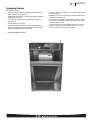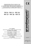
1
Air
Air Handlers
RF1T/RF1P Series
Rheem Air Handler
RF1T- Series
X-13 (ECM) Motor
Efficiencies up to 16 SEER
RF1P- Series
PSC Motor
Efficiencies up to 14.5 SEER
•
•
•
•
•
•
•
•
Front or Bottom Return with aluminum tube and fin coil
Flow Check Piston for cooling or heat pump operation
Wall-hanging brackets
Built in Filter Rack
Suitable for R-410A or R-22 Refrigerants (RF1P Only)
AHRI Certified
UL Certified
Molex Plug Connections for field installed heater kits
• Dual Voltage Direct Drive Blower with multi-speed motor
• Thermoplastic Drain Pan with bottom primary and secondary
connections
• Optional Decorative Grill for front return applications
• Optional Factory Installed Condensate Float Switch which
shuts off the outdoor unit in event the condensate pan
becomes clogged
FORM NO. H11-555
Air
Table of Contents
RF1T/RF1P Series
TABLE OF CONTENTS
Engineering Features ......................................................................................3
Model Number Identification ............................................................................4
Dimensional Data ........................................................................................5-6
Airflow Performance Data ............................................................................7-9
Piston Sizing Chart ........................................................................................10
Electrical Data ..............................................................................................11
Accessories ............................................................................................................12
Limited Warranty ..........................................................................................13
2
Air
Engineering Features
RF1T/RF1P Series
Engineering Features
RF1T/RF1P- Series
• The most compact unit design available, all standard heat air
handler models only 36" [915 mm].
• Rugged wall steel cabinet construction, designed for added
strength and versatility.
• 1.0" foil faced insulation for excellent thermal and sound
performance.
• Four leg blower motor mount.
• Traditional open wire element design for heat applications.
• Indoor coil design provides low air side pressure drop, high
performance and extremely compact size.
• Coils are constructed of aluminum fins and internally grooved
aluminum tubing.
• Molded polymer corrosion resistant condensate drain pan is
provided for all indoor coils.
• Connection point for high voltage wiring is inside the air handler cabinet. Low voltage connection is made on the outside
of the air handler cabinet.
• Concentric knockouts are provided for power connection to
cabinet. Installer may pull desired hole size up to 13/8 inch
inches [35 mm] for 7/8 inch [22 mm] conduit.
[ ] Designates Metric Conversions
3
Air
Model Number Identification
RF1T/RF1P Series
Model Number Identification
R F
Available Models
RF1P1821SPANJAB03
1 T 24 21 S P A N J A N 00 ***
RF1P1821SPANJAB05
Option Code
Blank = None
RF1P1821SPANJAB08
Factory Heat
00 = NO HEAT
03 = 3 kW
05 = 5 kW
08 = 8 kW
10 = 10 kW
RF1P2421SPANJAB03
Disconnect
B = Breaker
N = None
RF1P2421SPANJAB05
RF1P2421SPANJAB08
RF1P2421SPANJAB10
RF1P2421SPANJAN00
RF1P3024SPANJAB03
RF1P3024SPANJAB05
Minor Series
A = First
RF1P3024SPANJAB08
Voltage
J = 208/240/1/60
RF1P3024SPANJAN00
Controls
N = Non-communicating
RF1P3624SPANJAB05
Major Series
A = First
RF1P3624SPANJAN00
Metering Device
T = TEV
P = Piston
Efficiency
S = Standard
M = Medium
H = High
Width
21 = 21.5"
24 = 24"
Nominal Capacity
18 = 18,000 BTU/H [5.30 kW]
24 = 24,000 BTU/H [7.03 kW]
30 = 30,000 BTU/H [8.80 kW]
36 = 36,000 BTU/H [10.6 kW]
Motor Type
P = PSC
T = Constant Torque
Stage of Air Flow
1 = Single
Product Category
F = Front Return Air Handler
Rheem
4
RF1P1821SPANJAN00
RF1P3024SPANJAB10
RF1P3624SPANJAB03
RF1P3624SPANJAB10
RF1P3624STANJAB03
RF1P3624STANJAB05
RF1P3624STANJAB08
RF1P3624STANJAB10
RF1P3624STANJAN00
RF1T2421MTANJAB03
RF1T2421MTANJAB05
RF1T2421MTANJAB08
RF1T2421MTANJAB10
RF1T2421MTANJAN00
RF1T3624MTANJAB03
RF1T3624MTANJAB05
RF1T3624MTANJAB08
RF1T3624MTANJAB10
RF1T3624MTANJAN00
Note: All models available with option code 417
(float switch)
• Supply circuit protective devices may be fuses or
“HACR” type circuit breakers.
• Largest motor load is included in single circuit.
• If non-standard fuse size is specified, use the next
larger fuse size.
• J Voltage (230V) single-phase air handler is
designed to be used with single or three phase 230
volt power. In the case of connecting 3-phase
power to the air handler terminal block, bring only
two leads to the terminal block. Cap, insulate and
fully secure the third lead.
• The air handlers are shipped from the factory with
the proper indoor coil installed, and cannot be
ordered without a coil.
Air
Dimensional Data
RF1T/RF1P Series
Unit Dimensions
Unit Dimensions & Weights
Dimensional Data
Model
RF1P18
RF1P24
RF1P30
RF1P36
RF1T24
RF1T36
(A) Unit
Width
In. [mm]
211/2
[546.1]
211/2 [546.1]
241/2 [609.6]
241/2 [609.6]
211/2 [546.1]
241/2 [609.6]
(B) Unit
Height
In. [mm]
36 [914.4]
36 [914.4]
36 [914.4]
36 [914.4]
36 [914.4]
36 [914.4]
(C) Unit
Depth
In. [mm]
17 [431.8]
17 [431.8]
21 [533.4]
21 [533.4]
17 [431.8]
21 [533.4]
(D) Return
Air Opening
Width
In. [mm]
20 [508]
20 [508]
23 [584.2]
23 [584.2]
20 [508]
23 [584.2]
(E) Return
Air Opening
Height
In. [mm]
177/16
[442.9]
177/16 [442.9]
213/88 [542.9]
213/88 [542.9]
177/16 [442.9]
213/88 [542.9]
Air Flow
CFM (Nom.) [L/s]
Low
High
600 [283]
800 [378]
1000 [472]
1200 [566]
600 [283]
1000 [472]
—
—
—
—
800 [378]
1200 [566]
Unit Weight/
Shipping Weight (Lbs.) [kg]
80 [36] / 90 [41]
80 [36] / 90 [41]
95 [43] / 105 [48]
95 [43] / 105 [48]
95 [43] / 105 [48]
95 [43] / 105 [48]
[ ] Designates Metric Conversions
5
Air
Dimensional Data
RF1T/RF1P Series
Unit Dimensions (con’t.)
11/2 & 2 TON [5.28 & 7.03 kW] MODELS
[ ] Designates Metric Conversions
6
21/2 & 3 TON [8.79 & 10.6 kW] MODELS
Air
Airflow Performance Data
RF1T/RF1P Series
Airflow Performance
Airflow performance data is based on cooling performance
with a coil and filter in place. Select performance table for
appropriate unit size, voltage and number of electric heaters to
be used. Make sure external static applied to unit allows operation within the minimum and maximum limits shown in table
below for both cooling and electric heat operation. For optimum blower performance, operate the unit in the .3 [8 mm] to
.7 inches [18 mm] W.C. external static range. Units with coils
should be applied with a minimum of .1 inch [3 mm] W.C.
external static range.
Airflow Operating Limits
Cooling BTUH x 1,000
Cooling Tons Nominal
-18
1.5
-24
2
-30
2.5
-36
3
Heat Pump or Air Conditioning
Maximum Heat/Cool CFM [L/s]
(37.5 CFM [18 L/s]/1,000 BTUH)
(450 CFM [212 L/s]/Ton Nominal)
675
[319]
900
[425]
1125
[531]
1350
[637]
Heat Pump or Air Conditioning
Nominal Heat/Cool CFM [L/s]
(33.3 CFM [16 L/s]/1,000 BTUH)
(400 CFM [189 L/s]/Ton Nominal)
600
[283]
800
[378]
1000
[472]
1200
[566]
Heat Pump or Air Conditioning
Minimum Heat/Cool CFM [L/s]
(30.0 CFM [14 L/s]/1,255 BTUH)
(360 CFM [170 L/s]/Ton Nominal)
540
[255]
720
[340]
900
[425]
1080
[510]
Maximum kW Electric Heating
& Minimum Electric Heat CFM [L/s]
8
450 [212]
10
690 [326]
10
808 [381]
10
976 [461]
Maximum Electric Heat Rise °F [°C]
54 [12]
44 [7]
44 [7]
44 [7]
[ ] Designates Metric Conversions
7
Air
Airflow Performance Data
RF1T/RF1P Series
208V/240V Airflow Performance Data—RF1P (PSC Motor)
Nominal
Manufacturer
Cooling
Recommended
Capacity Air-Flow Range
Tons [kW] (Min/Max) CFM
Blower Size/ Motor
Motor
Speed
HP [W] &
from
# of Speeds Factory
PSC
Motor
Speed
High
1.5
873/438
10X6 1/5 Hp
2 speed
dual voltage
High
Low
High
2
1137/764
10X6 1/5 Hp
2 speed
dual voltage
High
Low
High
2.5
1148/802
10X8T 1/4 Hp
2 speed
dual voltage
High
Low
High
3
1363/1048
10X8T 1/3 Hp
2 speed
dual voltage
CFM Dry Delivery/filter/heaters/RPM/Watts
High
Low
External Static Pressure-Inches W.C. [kPa]
0.1 [.02]
0.2 [.05]
0.3 [.07]
0.4 [.10]
0.5 [.12]
0.6 [.15]
CFM
873
828
785
751
707
—
—
RPM
897
923
948
955
981
—
—
Watts
288
286
283
280
274
—
—
CFM
572
543
508
477
438
—
—
—
RPM
706
753
791
830
869
—
Watts
184
181
187
178
172
—
—
CFM
1137
1097
1034
985
933
868
810
RPM
1101
1104
1114
1118
1124
1130
1136
Watts
438
444
446
421
391
377
360
CFM
867
855
827
798
764
—
—
RPM
864
902
948
978
1002
—
—
Watts
324
317
290
285
283
—
—
CFM
1148
1104
1040
980
926
855
750
RPM
862
889
918
943
962
984
1012
Watts
411
420
379
367
369
350
317
CFM
1000
958
910
853
802
—
—
RPM
788
823
855
889
914
—
—
Watts
343
344
346
322
317
—
—
CFM
1363
1303
1240
1169
1096
1030
—
RPM
1029
1047
1060
1082
1095
1104
—
Watts
515
514
468
428
428
394
—
CFM
1196
1158
1105
1048
—
—
—
RPM
958
984
1012
1037
—
—
—
Watts
423
402
402
360
—
—
—
Notes: • All 208/240V PSC motors have voltage taps for 208 and 240 volts.
• All 208/240V PSC motors are shipped on high speed and 240 volts.
• If the application external static is less than 0.5" WC, adjust the motor speed to the low static speed as described below:
• Unplug the black motor wire off the relay on the control board and plug in the red motor wire.
• Replace the cap on the black motor wire.
• Voltage change (208/240V motors):
• Move the orange lead to transformer 208V tap from 240V tap. Replace the wire cap on 240V tap.
• Unplug the purple motor wire off the transformer and plug in the yellow motor wire.
• Replace the cap on the purple motor wire.
• The above airflow table lists the airflow information for air handlers with maximum heater allowed for each model.
[ ] Designates Metric Conversions
8
0.7 [.17]
Air
Airflow Performance Data
RF1T/RF1P Series
208V/240V Airflow Performance Data—RF1T (X-13 (ECM) Motor)
Manufacturer
Nominal
Recommended
Cooling
Capacity Air-Flow Range
Tons [kW] (Min/Max) CFM
Blower Size/ Motor
Motor
Speed
HP [W] &
from
# of Speeds Factory
5
1.5
852/510
5
973/733
5
1145/894
5
1306/1040
5
4
3
10X8 1/2 Hp
2 speed
dual voltage
5
3
2
10X6 1/3 Hp
2 speed
dual voltage
5
2.5
3
10X6 1/3 Hp
2 speed
dual voltage
5
2
X-13
2
5
10X8 1/2 Hp
2 speed
dual voltage
5
CFM Dry Delivery/filter/heaters/RPM/Watts
Motor
Speed
4
External Static Pressure-Inches W.C.
0.1 [.02]
0.2 [.05]
0.3 [.07]
0.4 [.10]
0.5 [.12]
CFM
852
823
792
770
738
713
690
RPM
847
881
915
949
989
1026
1057
Watts
162
151
144
168
182
196
178
CFM
669
628
593
552
510
—
—
RPM
669
713
760
806
852
—
—
Watts
80
87
82
94
86
—
—
CFM
973
945
922
896
872
852
833
0.6 [.15]
0.7 [.17]
RPM
956
991
1020
1054
1083
1117
1145
Watts
222
221
247
256
253
261
260
CFM
841
807
780
753
733
—
—
RPM
849
890
925
957
992
—
—
Watts
160
168
179
187
187
—
—
CFM
1145
1122
1084
1064
1055
1025
1002
RPM
767
780
797
820
855
900
954
Watts
240
237
239
245
274
276
306
CFM
1037
1005
956
924
894
—
—
RPM
798
845
901
945
980
—
—
Watts
199
213
196
226
237
—
—
CFM
1306
1268
1223
1195
1162
1128
1093
RPM
887
933
986
1019
1056
1096
1133
Watts
307
313
313
339
373
356
370
CFM
1201
1163
1129
1094
1065
1040
—
RPM
866
914
964
999
1032
—
—
Watts
278
286
301
324
348
—
—
Notes: X-13 motor speed changes.
All X-13 motors have 5 speed taps. Speed tap 1 is for continuous fan. Speed tap 2 (low static) and speed tap 3 (high static) are for lower tonnage. Speed tap 4 (low
static) and speed tap 5 (high static) are for higher tonnage.
X-13 air handlers are always shipped from factory at speed tap 5. To change to 1.5-ton or 2.5-ton airflow, move the blue wire to speed tap 2 or 3 on the
X-13 motor. The low static speed tap 2 (lower tonnage) and 4 (higher tonnage) are used for external static below 0.5" WC. The high static speed tap 3 (lower tonnage)
and 5 (higher tonnage) are used for external static exceeding 0.5" WC. Move the blue wire to the appropriate speed tap as required by the application needs.
• The airflow for continuous fan (speed tap 1) is 50% of the speed tap 4 airflow.
• The above airflow table lists the airflow information for air handlers with maximum heater allowed for each model.
[ ] Designates Metric Conversions
9
Air
Piston Sizing Chart
RF1T/RF1P Series
Piston Sizing Chart
Indoor Unit
Factory Piston
RF1P1821SPANJA
0.047
RF1P2421SPANJA
0.053
RF1P3024SPANJA
0.061
RF1P3624SPANJA
0.065
10
SEER Rating
OD Unit
Nominal Tons
Refrigerant
Orifice Size
13
1.5
R410a
0.047
14
13
12
10
13
14
13
12
10
13
14
13
12
10
13
14
13
12
10
1.5
1.5
1.5
1.5
2
2
2
2
2
2.5
2.5
2.5
2.5
2.5
3
3
3
3
3
R410a
R22
R22
R22
R410a
R410a
R22
R22
R22
R410a
R410a
R22
R22
R22
R410a
R410a
R22
R22
R22
0.049
0.049
0.051
0.053
0.053
0.057
0.057
0.061
0.063
0.061
0.063
0.065
0.065
0.065
0.065
0.068
0.069
0.070
0.070
Air
Electrical Data
RF1T/RF1P Series
RF1P/RF1T Electrical Data – Blower Motor Only – No Electric Heat
1.5
Minimum
Circuit
Ampacity
3
Maximum
Circuit
Protector
15
1.5
2.5
3
4
15
15
2
2.5
4
15
4
4
1.6
2.7
3
4
15
15
Model/Nominal
Cooling Tons
Voltage
Phase
Hertz
HP [W]
RPM
Speeds
Circuit
Amps.
RF1P1821
208/230
1
60
1/5 [149]
1075
2
RF1P2421
RF1P3024
208/230
208/230
1
1
60
60
1/5 [149]
1/4 [186]
1075
1075
2
2
RF1P3624
208/230
1
60
1/3 [249]
1075
RF1T2421
RF1T3624
208/230
208/230
1
1
60
60
1/3 [249]
1/2 [373]
300-1100
300-1100
*Blower motors are all single phase motors.
RF1P/RF1T Electrical Data – with Electric Heat
Installation of the U.L. Listed original equipment manufacturer provided heater kits listed in the table below is recommended for all
auxiliary heating requirements.
Cooling
Capacity Tons
RF1P/RF1T
18
RF1P/RF1T
24
RF1P/RF1T
30
RF1P/RF1T
36
Model
No.
RXHJ-21B/T03J
RXHJ-21B/T05J
RXHJ-21B/T08J
RXHJ-21B/T03J
RXHJ-21B/T05J
RXHJ-21B/T08J
RXHJ-21B/T10J
RXHJ-24B/T03J
RXHJ-24B/T05J
RXHJ-24B/T08J
RXHJ-24B/T10J
RXHJ-24B/T03J
RXHJ-24B/T05J
RXHJ-24B/T08J
RXHJ-24B/T10J
Heater
kW
(208/240V)
2.25/3.0
3.6/4.8
5.4/7.2
2.25/3.0
3.6/4.8
5.4/7.2
7.2/9.6
2.25/3.0
3.6/4.8
5.4/7.2
7.2/9.6
2.25/3.0
3.6/4.8
5.4/7.2
7.2/9.6
PH/Hz
No. Elements kW Per
Type Supply
Circuit
Circuit
Amps.
Motor
Ampacity
Minimum
Circuit
Ampacity
Maximum
Circuit
Protection
1/60
1/60
1/60
1/60
1/60
1/60
1/60
1/60
1/60
1/60
1/60
1/60
1/60
1/60
1/60
1-3.0
1-4.8
2-3.6
1-3.0
1-4.8
2-3.6
2-4.8
1-3.0
1-4.8
2-3.6
2-4.8
1-3.0
1-4.8
2-3.6
2-4.8
Single
Single
Single
Single
Single
Single
Single
Single
Single
Single
Single
Single
Single
Single
Single
10.8/12.5
17.3/20.0
26.0/30.0
10.8/12.5
17.3/20.0
26.0/30.0
34.6/40.0
10.8/12.5
17.3/20.0
26.0/30.0
34.6/40.0
10.8/12.5
17.3/20.0
26.0/30.0
34.6/40.0
1.5
1.5
1.5
1.5
1.5
1.5
1.5
2.5
2.5
2.5
2.5
2.5
2.5
2.5
2.5
16/18
24/27
35/40
16/18
24/27
35/40
46/52
17/19
25/29
36/41
47/54
17/19
25/29
36/41
47/54
20/20
25/30
35/40
20/20
25/30
35/40
50/60
20/20
25/30
40/45
50/60
20/20
25/30
40/45
50/60
• Electric heater BTUH - (heater watts + motor watts) x 3.414 (see airflow table for motor watts.)
• Supply circuit protective devices may be fused or “HACR” type circuit breakers.
• If non-standard fuse size is specified, use next size larger standard fuse size.
• Largest motor load is included in single circuit or circuit 1 of multiple circuits.
• No electrical heating elements are permitted to be used with A Voltage (115V) air handler.
• J voltage (230V) single phase air handler is designed to be used with single or three phase
230 volt electric heaters. In the case of connecting 3 phase power to air handler terminal block
without the heater, bring only two leads to terminal block, cap, insulate and fully secure the third lead.
• Do not use 480 volts electrical heaters on 230 volts air handler.
Electrical Wiring:
Power Wiring
Grounding
• Field wiring must comply with the National Electrical Code
(C.E.C. in Canada) and any applicable local ordinance.
• This product must be sufficiently grounded in accordance with
National Electrical Code (C.E.C. in Canada) and any applicable
local ordinance.
• Supply wiring must be 75°C minimum copper conductors only.
• See electrical data for product Ampacity rating and Circuit
Protector requirement.
• A grounding lug is provided.
[ ] Designates Metric Conversions
11
Air
Accessories
RF1T/RF1P Series
16.0 Accessories-Kits-Parts
• Drain Pan Over Flow Switch RXHK-A01 is used to detect condensate drain blockage and will shut down the outdoor unit in order to
prevent structural damage to the surrounding structures of the air handler.
• Bottom Return Conversion Kit RXHK- is used to divert the return air from the factory standard front return to a bottom return.
Accessory Number
RXHK-B01
RXHK-B02
Indoor Unit
RF1P-FR18
RF1P-FR24
RF1T-FR24
RF1P-FR30
RF1P-FR36
RF1T-FR36
• Louvered Cabinet Grill RXHK- is used as decorative grill which covers the return air opening of the front return air handler.
Accessory Number
RXHK-C01
RXHK-C02
Indoor Unit
RF1P-FR18
RF1P-FR24
RF1T-FR24
RF1P-FR30
RF1P-FR36
RF1T-FR36
• Decorative Wall Grill RXHK-D01 is used in applications where the air handler is installed in a closet or interior wall and allows
adequate return air back to the unit.
[ ] Designates Metric Conversions
12
Air
Limited Warranty
RF1T/RF1P Series
GENERAL TERMS OF LIMITED WARRANTY*
Rheem will furnish a replacement for any part of this product
which fails in normal use and service within the applicable
periods stated, in accordance with the terms of the limited
warranty.
Conditional Parts (Registration Required) ..........Ten (10) Years
*For complete details of the Limited and Conditional Warranties, including
applicable terms and conditions, contact your local contractor or the
Manufacturer for a copy of the product warranty certificate.
13
Air
14
Notes
RF1T/RF1P Series
Air
Notes
RF1T/RF1P Series
15
The new degree of comfort.™
In keeping with its policy of continuous progress and product improvement, Rheem reserves the right to make changes without notice.
Rheem Heating, Cooling & Water Heating • P.O. Box 17010
Fort Smith, Arkansas 72917 • www.rheem.com
Rheem Canada Ltd./Ltée • 125 Edgeware Road, Unit 1
Brampton, Ontario • L6Y 0P5
PRINTED IN U.S.A. 12/14 QG FORM NO. H11-555