1
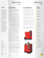
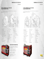
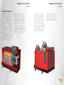
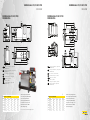
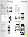
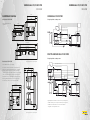
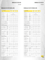
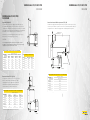
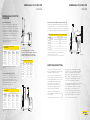
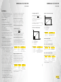
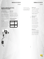
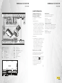
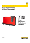
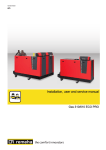
THE
SMARTER
WAY TO
REDUCE
EMISSIONS
REMEHA
CONDENSING
BOILER
RANGE
The most efficient way to
reduce your carbon footprint.
GAS 310/610 ECO PRO
2
3
REMEHA GAS 310/610 ECO PRO
OVERVIEW
REMEHA GAS 310/610 ECO PRO
OVERVIEW
INTRODUCTION
BOILER DESCRIPTION
APPLICATION INFORMATION
60% of the buildings that will be
standing in 2050 are already here with
us today. So tomorrow, there will be
a great need for intelligent heating
technology specifically designed
for refurbished buildings. This is
where Remeha’s advanced thinking
is leading the way. To a future where
our highly efficient heating systems
help to improve the overall energy
efficiency of refurbished buildings.
Giving them new life and a more
sustainable future.
The Remeha Gas 310/610 ECO PRO boilers are fully assembled, free
standing, gas fired (Natural gas only), fully modulating, high efficiency
condensing boilers and are supplied on wheels for easy manoeuvrability
into the boiler house.
The Remeha Gas 310/610 ECO PRO boilers can be used on all new
and refurbishment projects in both single and multiple configurations.
Conventional and room sealed flue system capability means that the boiler
can be sited almost anywhere within a building.
The sectional cast aluminium heat exchanger and other major
components are contained within a rigid steel frame with removable
casing parts for maintenance purposes. The Remeha Gas 310 ECO PRO
and each Remeha Gas 610 ECO PRO module frame is fitted with a set of
wheels to enable the assembled unit to be easily manoeuvred into position
within the plant room on site with the minimum of effort. All major
electrical and electronic controls are contained within the instrument
panel mounted on top of the boiler at the opposite end to the connections
facing to the front (long side) but can be rotated 90˚ towards the short
side to suit site location. The Remeha Gas 310 ECO PRO boiler is available
with flow and return connections on the left or right hand end of the boiler
(this must be decided at time of order), with the gas connection on the top
of the boiler. The flue gas outlet, complete with a condensate connection,
is at low level on the same end as the F/R connections. The combustion
air inlet is located at the top of the boiler. The Remeha Gas 610 ECO PRO
boiler has two flows and returns at one end of the boiler with a combined
flue gas outlet. The boiler is not available with a choice between left or
right hand versions, but the control panel can easily be rotated to enable
the boiler connections to be on the left or right hand side.
The Remeha iSense and “OpenTherm” weather compensators (option) are
able to communicate directly with the boilers’ controls to make full use of
their fully modulating features, ensuring that the boiler closely matches
the system demand at all times.
The Remeha Gas 310 ECO PRO and
the Remeha Gas 610 ECO PRO are
compact, floor standing condensing
boilers. Their small footprint and
ability to be installed side to side
makes them ideally suited for
modular configuration. An optional
Optimising Weather Compensating
control package is available to ensure
maximum efficiency. The boilers are
suitable for both new and retrofit
applications. With conventional and
room sealed capability, they can be
installed in most situations.
CONTENTS
Introduction 2
Boiler description 2
Application information 3
Advantages at a glance 3
Typical boiler construction 4-5
Operating principle 6-7
Dimensions 8-11
Maintenance areas 12-13
Technical data 14-15
Flue data 16-19
Controls 20-21
Electrical connections 22-24
Safety interlocks 25-27
The boilers are suitable for room sealed or conventional flue applications
and have been designed for central heating and indirect hot water
production at working pressures not exceeding 7 bar. They must be
installed on a fully pumped system and are designed for operating
pressures between 0.8 and 7 bar.
The pre-mix gas burner (NG only) with its gas/air ratio control system
ensures clean, trouble-free operation with higher than average annual
efficiencies of up to 109.35% Hi (NCV) in the condensing mode combined
with ultra low NOx and minimum CO2 emissions. The standard control
package allows for external On/Off, High Low (volt free switch/s) or
Modulating control (0-10V input). The built-in digital display shows normal
operating/fault code indication and allows actual and set values to be read
and adjusted.
The intelligent, advanced boiler control (‘abc®’) continuously monitors the
boiler operating conditions, varying the heat output to suit the system load.
The control is able to react to external “negative” influences in the rest of
the system (flow rates, air/gas supply problems) maintaining boiler output
for as long as possible without resorting to a lockout condition. At worst,
the boiler will reduce its output and/or shut down (shut off mode) awaiting
the “negative” conditions to return to normal before restarting. The ‘abc®’
control cannot override the standard flame safety controls.
All Remeha Gas 310/610 ECO PRO boilers are tested after assembly to
ensure the boiler and controls comply to our strict quality policy.
External control systems (BMS) can be interfaced with the boiler to provide
on/off - or modulating (0-10V) control options.
A key benefit of the Remeha Gas 310/610 Eco Pro is that it is Renewable
Energy Ready. Most renewable energy products need to be backed up by
a condensing boiler during periods of peak demand.
The secondary return feature on the new Remeha Gas 310/610 Eco Pro
makes this boiler particularly suitable for use with renewable energy
technologies that use low grade heat such as heat pumps or underfloor
heating circuits.
Bivalent systems such as this combine the best of renewable and
conventional heating technologies to maximise the seasonal efficiency
of the system as a whole over the course of the year.
ADVANTAGES
AT A GLANCE
Inspected for compliance
Lightweight construction
Easy disassembly
Supplied with wheels for quick
and easy installation
High efficiency - 106.8%
at 50°C/30°C (NCV)
Boiler controls on/off high/low or fully
modulating over 20%-100% (1:5)
Low NOx ≥ 35
Ultra quiet > 65 dBA
Digital Diagnostic Display
Cast - sectional aluminium
heat exchanger
Cylindrical, stainless steel,
premix burner
Control adjustable 20˚C-90˚C
Air pressure differential
sensor (LDS)
Temperature sensors for low
water level protection
Gas/air mixing system
with venturi
Electronic control and
protection equipment
Frost protection
Conventional or room
sealed capability
Menu controlled microprocessor
boiler control
Enhanced failure functionality
Compact at only 72cm wide fit through a standard door
Left or right hand version
Gas 310 ECO PRO
4
5
REMEHA GAS 310/610 ECO PRO
OVERVIEW
REMEHA GAS 310/610 ECO PRO
OVERVIEW
TYPICAL REMEHA GAS 310 ECO PRO
BOILER CONSTRUCTION
TYPICAL REMEHA GAS 610 ECO PRO
BOILER CONSTRUCTION
The unit has been inspected for compliance with the essential requirements of the following directives:
CE identification number (PIN): 0063CL3613
NOx Class: 5
The unit has been inspected for compliance with the essential requirements of the following directives:
CE identification number (PIN): 0063CL3613
NOx Class: 5
1
Flow connection
12 Heat exchanger
26 Jacking bolt
2
Air differential
pressure switch
27 Gas connection
3
Flue gas discharge pipe
4
Return connection
14 Air inlet 34 Fan
5
Outlet for measuring
combustion gases
6 Flue gas thermostat (option)
7 Condensate collector
sealant cap
8 Pivoting castor
9 Jacking bolt
10 Base frame
11 Connection for second
return (optional)
insulation kit (option)
13 Boiler casing
15 Burner
16 Adapter
17 Ignition/ionization electrode
18 Heat exchanger
19 Inspection hatch
20 Heat exchanger sensor
21 Return sensor
22 Gas filter
23 Data plate
24 Siphon
25 Fixed castor
28 Gas pressure
measurement point
29 Control panel
30 Location for optional
features or a control unit
31 Pressure measurement point
32 Sight glass
33 Non-return valve
35 Extension piece
36Venturi
37 Gas block
38 Air inlet hose
39 Document holder
EFFICIENCY INFORMATION
Average Annual Efficiency DIN 4702 Part 8
Up to 109.35% at Hi
a. Up to 98.4% at Hi at an average water
temperature of 70°C (80°C/60ºC)
b. Up to 106.8% at Hi at an average water
temperature of 40°C (50°C/30°C)
Maintenance Consumption
Average 0.15 at 30K
ΔT = Boiler temp - Ambient temperature
NOTE: NCV = Hi, GCV = Hs
1
Flow connection
12 Flue gas collector
27 Gas connection
2
Air differential
pressure switch
13 Boiler casing
28 Gas pressure
measurement point
3
Flue gas discharge pipe
14 Air inlet
4
Return connection
5
Outlet for measuring
combustion gases
6
Flue gas thermostat (option)
7
Condensate collector
sealant cap
8
Pivoting castor
9
Jacking bolt
10 Base frame
11 Heat exchanger
insulation kit (option)
15Burner
16Adapter
17 Ignition/ionization electrode
18 Heat exchanger
19 Inspection hatch
20 Heat exchanger sensor
21 Return sensor
22 Gas filter
23 Data plate
24 Siphon
25 Fixed castor
26 Jacking bolt
29 Control panel
30 Location for optional
features or a control unit
31 Pressure measurement point
32 Sight glass
33 Non-return valve
34Fan
35 Extension piece
36Venturi
37 Gas block
38 Air inlet hose
39 Document holder
6
7
REMEHA GAS 310/610 ECO PRO
OVERVIEW
REMEHA GAS 310/610 ECO PRO
OVERVIEW
OPERATING PRINCIPLE
Combustion air is drawn into the inlet connection
from the plant room (conventionally flued)
or from outside via the eccentric flue system
(room sealed) by an air supply fan.
On the inlet side of the fan is a specially designed
chamber (venturi unit) which takes gas from
the multiblock and mixes it in the correct
proportions with the incoming air. This mixing
system ensures that the correct gas/air ratio is
delivered to the pre-mix burner at all times.
Depending on demand (under the dictates of flow/
return sensor and other external/internal control
inputs) the ‘abc®’ system determines the required
boiler output. The ‘abc®’ control then varies the
speed of the air supply fan which alters the volume
of air being drawn into the venturi. This change in
volume is measured using air pressure differential
which directly controls the volume of gas also being
delivered to the venturi. The resultant controlled
mixture is delivered to the premix burner.
This mixture is initially ignited by the combined
ignition/ionisation probe, which monitors the
state of the flame. Should the flame be unstable
or not ignite within the pre-set safety time cycle,
the controls will (after 5 attempts) shut the boiler
down requiring manual intervention to reset the
boiler. The digital display will indicate a flashing
fault code confirming the reason for the failure.
The products of combustion in the form of hot
flue gases are forced through the heat exchanger
transferring their heat to the system water (the flue
gas temperature is reduced to approximately 5°C/8°C
above the temperature of the system return water)
then discharged via the condensate collector, to the
flue gas outlet connection, to the atmosphere.
There will be a vapour cloud formed at the flue
gas terminal, because of the low flue gas exit
temperature - this is not smoke, simply water
vapour formed during the combustion process.
When the flue gas temperature falls below dew
point (55°C), water vapour (created during the
combustion process) will begin to condense out
in the boiler, transferring its latent heat into the
system water, thereby increasing the output of the
boiler without increasing the gas consumption.
Condensation formed within the boiler and flue
system is discharged from the boiler to an external
drain via the drain pan and siphon supplied.
The boiler can be supplied as an option with
a second (constant temperature) return
connection. This additional connection enables
the boiler to make full use of its condensing
ability whilst accepting both fixed and variable
temperature returns from the same system.
8
9
REMEHA GAS 310/610 ECO PRO
OVERVIEW
REMEHA GAS 310 ECO PRO
DIMENSIONS
REMEHA GAS 310/610 ECO PRO
OVERVIEW
REMEHA GAS 610 ECO PRO
DIMENSIONS
C
Ø 250
L
353
1460
592
722
353
592
2
920
8
155
65
310
447
366
130
65
1293
1310
Ø 250
2
320
1023
2
1477
80
1500
1726
8
641
B
353
A
C
894,5
L
320
B
2
Heating circuit flow (80mm) ” ;” Flange NW 80
(Standard DIN 2576)
Heating circuit flow (80mm) ” ;” Flange NW 80
(Standard DIN 2576)
Heating circuit return (65mm) ” ;” Flange NW 80
(Standard DIN 2576)
Heating circuit return (65mm) ” ;” Flange NW 80
(Standard DIN 2576)
Condensates discharge” ;” 1¼” (Internal)
Condensates discharge” ;” 1¼” (Internal)
Flue gas outlet” ;” Ø 350mm
Flue gas outlet” ;” Ø 250mm
Air intake” ;” Ø 250mm
Air supply collector (Optional)” ;” Ø 350mm
Air intake” ;” Ø 250mm
Second return (optional)” ;” Flange NW 80
(Standard DIN 2576)
2
Remeha Gas 310 ECO PRO
Boiler type
A (mm)
B (mm)
C (mm)
D (mm)
310-285 (5)
1833
1635
1862
1490
310-355 (6)
1833
1635
1862
1490
310-430 (7)
1833
1635
1862
1490
310-500 (8)
2142
1944
2172
1800
310-575 (9)
2142
1944
2172
1800
310-650 (10)
2142
1944
2172
1800
1760
T003766-F
Gas connection” ;” G2” (Female thread)
Gas connection” ;” G2” (Female thread)
2
310
T003472-G
155
A
1293
366
716
1477
130
920
1310
1500
592
706
1023
2
NOTE: Heating flow pipe 80mm
with a mating flange NW 80 (PN16)
Return flow pipe 65mm with
a mating flange NW 80 (PN16)
The optional return pipe is also
65mm and fitted with a NW80
(PN16) mating flange
The service areas are shown on page 12/13.
Second return (optional)” ;” Flange NW 80
(Standard DIN 2576)
Remeha Gas 610 ECO PRO
Boiler type
A (mm)
B (mm)
C (mm)
D (mm)
610-570 (5)
1833
1635
1862
1490
610-710 (6)
1833
1635
1862
1490
610-860 (7)
1833
1635
1862
1490
610-1000 (8)
2142
1944
2172
1800
610-1150 (9)
2142
1944
2172
1800
610-1300 (10)
2142
1944
2172
1800
NOTE: Heating flow pipe 80mm
with a mating flange NW 80 (PN16)
Return flow pipe 65mm with
a mating flange NW 80 (PN16)
The optional return pipe is also
65mm and fitted with a NW80
(PN16) mating flange
10
11
REMEHA GAS 310/610 ECO PRO
OVERVIEW
REMEHA GAS 310/610 ECO PRO
OVERVIEW
REMEHA GAS 310 ECO PRO
DIMENSIONS
REMEHA GAS 610 ECO PRO
DIMENSIONS
The service side with the inspection hatch on the heat
exchanger is considered to be the front of the boiler.
The Remeha Gas 310 ECO PRO boiler is available in both
a left-hand and right-hand version. This means that the
hydraulic connections and the flue gas discharge are
situated on either the left or the right-hand side of the
boiler. The control panel is on the front as standard,
but can easily be rotated so that it is on the short side.
The Remeha Gas 610 ECO PRO boiler is not available
with a choice between left or right hand versions, but
the control panel can easily be rotated to enable the
boiler connections to be on the left or right hand side.
I
L Left version
R Right version
I Inspection hatch
Remeha Gas 610 ECO PRO
Boiler type
Boiler type
610-570
1160
723
610-710
1160
310-430
723
610-860
1160
310-500
1032
610-1000
1469
310-575
1032
610-1150
1469
C + 1100*
55
531
87,5
800*
C + 600
C + 600
300
300
800*
150
55
C
800*
150
55
21,5
800*
150
2540*
800*
720
720
663
300
The frame section on the instrument
panel side
1450
1525*
4790*
3050*
531
55
87,5
T003474-B
Diagram shows position
of support feet
800*
150
55
* Indicates spacing required if this is
the operating side
720
800*
673
800*
150
720
See the diagram and table for the dimensions of
the largest remaining transport part, the frame
section with heat exchanger and water connections.
For information on fitting the parts, refer to the
assembly instructions delivered with the boiler.
55
C + 1100*
A
n
55
531
800*
55
Gas/air components
55
SPACE SAVING CONFIGURATIONS
If required for internal transport, the boiler can
be dismantled into smaller parts for transport.
The boiler can be stripped of :
Casing components
21,5
55
1469
The wheels are designed for transport purposes
only and not for use when the boiler is in its
final position.
n
55
55
55
87,5
CAUTION
n
663
55
673
723
310-355
610-1300
663
55
L (mm)
310-285
1032
21,5
A
Remeha Gas 310 ECO PRO
310-650
R
T003785-C
To make the boiler level and to raise the wheels off
the floor, the adjustment bolts must be used. Turn
the adjustment bolts out as soon as the boiler is
placed in the correct position. The picture shows the
support surface of the boiler. This is the position of
the adjustment bolts.
55
To make the boiler level and to raise the wheels off
the floor, the adjustment bolts must be used. Turn the
adjustment bolts out as soon as the boiler is placed
in the correct position. The picture shows the support
surface of the boiler. This is the position of the
adjustment bolts.
A (mm)
I
L
C
300
12
13
REMEHA GAS 310/610 ECO PRO
OVERVIEW
MAINTENANCE AREAS
C + 1100*
800*
C + 600
Remeha Gas 310 ECO PRO
C
300
For the dimensions of C/C1,
see page 8
SINGLE GAS 310 ECO PRO
Using the optional secondary return
300
800*
C + 1100*
REMEHA GAS 310/610 ECO PRO
OVERVIEW
800*
720
High Temperature Flow
Gas
Low Temperature Flow
150
720
800*
3190*
300
720
1670*
C
300
800*
150
C + 600
High Temperature Return
Low Temperature Return
C + C1 + 2200*
800*
800*
C1
C
600
Condensate
300
720
300
MULTIPLE BOILER GAS 310 ECO PRO
800*
1670*
150
C + C1 + 1200
Using the optional secondary return
T003499-B
Remeha Gas 610 ECO PRO
* Spacing required if this is operating side.
High Temperature Flow
For the dimensions of C/C1, see page 9
Low Temperature Flow
3050*
800*
800*
1450
300
800*
High Temperature Return
Gas
Low Temperature Return
C
A technical clearance of at least 80 cm is required at the
front (service side) of the boiler. However, we recommend
that the clearance is at least 100 cm. We recommend a
clearance of at least 40 cm above the boiler. If the air supply
filter is used, there must be a clearance of at least 65 cm.
A minimum of 30 cm is required on the side of the flue gas
discharge, and a minimum of 30 cm is also required on
the other side, or 80 cm, if this is the operating side.
C + 1100*
800*
E*
300
D
C
800*
300
600
C + 600
800*
300
800*
1525*
1450
3050*
C
Condensate
T003768-E
* Spacing required if this is operating side.
Typical diagrams shown do not constitute a full system design and
should be used for general concept information only. All equipment
should be installed to manufacturers instructions and must
comply with current regulations in force.
Condensate
14
15
REMEHA GAS 310/610 ECO PRO
OVERVIEW
REMEHA GAS 310 ECO PRO TECHNICAL DATA
Remeha Gas 310 ECO PRO
REMEHA GAS 310/610 ECO PRO
OVERVIEW
REMEHA GAS 610 ECO PRO TECHNICAL DATA
285
355
430
500
575
650
5
6
7
8
9
10
General
Remeha Gas 610 ECO PRO
570
710
2x5
2x6
860
1000
1150
1300
2x7
2x8
2x9
2x10
148
1060
158
1202
General
Number of sections
-
EC indentification no.
-
PIN
Flow rate setting
Adjustable
Norminal output (Pn)
minimum
maximum(1)
Heating System (80/60°C)
Norminal output (Pn)
maximum (1)
Heating System (50/30°C)
Norminal input (Qn)
minimum
maximum(1)
(Hs)
Norminal input (Qn)
minimum
maximum(1)
(Hi)
Full load water efficiency (Hi) (80/60°C)%
0063CL3613
Number of sections
-
EC indentification no.
Modulating, Start/Stop, 0-10V
65
79
92
327
395
46
kW
51
261
kW
279
350
425
497
574
651
75
369
68
333
98.1
96
445
82
402
98.2
105
520
95
469
98.3
121
598
109
539
98.4
135
677
122
610
98.5
Flow rate setting
Adjustable
Norminal output (Pn)
minimum
maximum(1)
Heating System (80/60°C)
Norminal output (Pn)
minimum
maximum(1)
Heating System (50/30°C)
Norminal input (Qn)
minimum
maximum(1)
(Hs)
Norminal input (Qn)
minimum
maximum(1)
(Hi)
Full load water efficiency (Hi) (80/60°C)%
106
530
119
601
-
PIN
0063CL3613
Modulating, Start/Stop, 0-10V
87
123
122
654
790
922
kW
69
522
kW
558
700
850
994
1148
1303
101
738
91
666
98.1
142
890
128
804
98.2
141
1038
127
938
98.3
170
1196
170
1078
98.4
180
1354
162
1220
98.5
%
60
295
54
266
98.0
%
80
590
72
532
98.0
Full load water efficiency (Hi) (50/30°C)%
%
104.8
105.2
105.6
106.0
106.4
106.8
Full load water efficiency (Hi) (50/30°C)%
-
104.8
105.2
105.6
106.0
106.4
106.8
Low load water efficiency (Hi) (Return temp 60°C)
Annual efficiency G20 (Emission 02 = 0%)
(DIN 4702, Part 8)
Data on the gases and combustion gases
%
94.7
95.3
95.8
96.3
96.8
97.3
%
94.7
95.3
95.8
96.3
96.8
97.3
%
109.6
109.5
109.4
109.3
109.2
109.1
Low load water efficiency (Hi) (Return temp 60°C)
Annual efficiency G20 (Emission 02 = 0%)
(DIN 4702, Part 8)
Data on the gases and combustion gases
%
109.6
109.5
109.4
109.3
109.2
109.1
5.7
28.1
17
30
2.3
7.2
35.2
17
30
2.3
8.7
42.5
17
100
2.3
10.1
49.6
17
100
2.3
11.5
57.0
17
100
2.3
12.9
64.6
17
30
2.3
7.6
56.2
17
30
2.3
9.6
70.4
17
30
2.3
13.5
85.0
17
100
2.3
13.4
99.2
17
100
2.3
16.2
114.0
17
100
2.3
17.2
129.2
17
30
2.3
33
571
0.21
91
448
35
591
0.18
114
560
32
611
0.15
138
676
29
630
0.13
160
789
36
650
0.12
183
907
26
670
0.11
205
1026
33
1142
0.21
182
896
35
1182
0.18
228
1120
32
1222
0.15
276
1352
29
1260
0.13
320
1578
36
1300
0.12
366
1814
26
1340
0.11
410
2052
130
130
150
164
186
208
minimum
maximum
minimum
maximum
Gas consumption G20 (Gas H)
Gas inlet pressure G20 (Gas H)
Flue gas losses
kW
kW
ms 3/h
mbar
%
NOx-Emission per year (BREEAM) (EN 15420)
Maintenance consumption (Ps)
(ΔT = 30K)(2)
Mass flue gas flow rate
minimum
maximum
minimum
maximum
Flue gas temperature
Maximum counter pressure
mg/kWh
W
%
kg/h
30
80
°C
Pa
130
120
minimum
maximum
minimum
maximum
Gas consumption G20 (Gas H)
Gas inlet pressure G20 (Gas H)
Flue gas losses
130
150
150
150
kW
ms 3/h
mbar
%
NOx-Emission per year (BREEAM) (EN 15420)
Maintenance consumption (Ps)
(ΔT = 30K)(2)
Mass flue gas flow rate
minimum
maximum
minimum
maximum
Flue gas temperature
Characteristics of the heating circuit
kW
Maximum counter pressure
mg/kWh
W
%
kg/h
30
80
°C
Pa
130
120
130
l
98
120
142
Characteristics of the heating circuit
Water content
l
49
60
71
82
Water operating pressure
minimum
bar
Water operating pressure (PMS)
maximum
bar
7
Water temperature
maximum
°C
Operating temperature
minimum
maximum
°C
Factory setting
°C
mbar
kPa
mbar
kPa
110
20
90
80
Water resistance (ΔT = 20K)
Water resistance (ΔT = 10K)
93
104
0.8
113
11.3
374
37.4
110
11
364
36.4
120
21
397
39.7
110
1
364
36.4
125
12.5
413
41.3
130
13.0
435
43.5
Electrical characteristics
Water content
Water operating pressure
minimum
bar
Water operating pressure (PMS)
maximum
bar
7
Water temperature
maximum
°C
Operating temperature
minimum
maximum
°C
Factory setting
°C
mbar
kPa
mbar
kPa
110
20
90
80
Water resistance (ΔT = 20K)
Water resistance (ΔT = 10K)
0.8
113
11.31
374
37.4
110
11
364
36.4
120
21
397
39.7
110
11
364
36.4
125
12.5
413
41.3
130
13.0
435
43.5
Electrical characteristics
Power supply voltage
Power consumption - Full load
maximum
VAC/Hz
AT
AT
W
279
334
230/50
10
2
426
543
763
723
Power consumption - Full load
maximum
VAC/Hz
AT
AT
W
558
668
230/50
10
2
852
1086
1526
1446
Power consumption - Part load
maximum
W
46
46
58
61
62
55
Power consumption - Part load
maximum
W
929
82
116
122
124
110
Power consumption - Standby
maximum
W
6
6
6
6
6
6
Power consumption - Standby
maximum
W
12
12
12
12
12
12
F2 Circuit-breaker
F1 control PCB
Fuse (230 VAC)
Electrical protection index
IP
Power supply voltage
Fuse (230 VAC)
X1B
Electrical protection index
(3)
Other characteristics
Weight (empty)
(1) Factory setting
IP
X1B
(3)
Other characteristics
Total
Acoustic level at 1 metre
Ambient temperature
F2 Circuit-breaker
F1 control PCB
maximum
(2) ΔT = Boiler temp - Ambient temperature
kg
364
398
433
495
531
568
Weight (empty)
dB(A)
61
61
65
65
65
65
Acoustic level at 1 metre
°C
(3) For a room sealed operation
40
Total
Ambient temperature
(1) Factory setting
maximum
(2) ΔT = Boiler temp - Ambient temperature
kg
707
771
837
957
1025
1095
dB(A)
64
64
68
68
68
68
°C
(3) For a room sealed operation
40
16
17
REMEHA GAS 310/610 ECO PRO
OVERVIEW
REMEHA GAS 310/610 ECO PRO
OVERVIEW
REMEHA GAS 310 ECO PRO
FLUE DATA
Open flue (B23, B23P)
Connection in areas of different pressure (C53, C83)
If using an open version, the air supply opening remains open; only
the combustion gas opening is connected. The boiler then takes in the
combustion air required directly from the premises in which it is installed.
For the application of air discharge and combustion gas discharge piping
with a diameter other than 250 mm, a reducer should be used.
Combustion air supply and combustion gas discharge are possible in various pressure zones,
semi-CLV systems. With the exception of coastal areas. The maximum permissible difference
in height between the combustion air supply and the combustion gas discharge is 36 m.
L
250/230 mm 'Cone'
c/w bird guard
500 mm
Min
If the boiler, in room ventilated operation, has been set up in a (very)
dusty room, use the air supply filter (= accessory).
The air supply opening must remain open. The premises in which
the appliance is installed must be fitted with the necessary air supply
openings. They must not be reduced or closed.
Maximum height
difference 36M
CAUTION
T003497-D
L
Chimney length for the open version - Gas 310 ECO PRO
Maximum length (L)1
Pipe reductions per element used
Boiler type
with a Ø of
150mm
with a Ø of
180mm
with a Ø of
200mm
with a Ø of
250mm
310-285 (5)
20m
50m
50m
50m
Diameter
310-355 (6)
11m
30m
50m
50m
310-430 (7)
8m
22m
39m
50m
310-500 (8)
7m
18m
32m
310-575 (9)
5m
13m
24m
310-650 (10)
5m
12m
21m
Elbow 45°
Elbow 90°
150mm
1.2m
2.1m
180mm
1.4m
2.5m
50m
200mm
1.6m
2.8m
50m
250mm
2.4m
3.5m
50m
300mm
2.4m
4.2m
250mm Air Inlet Grill
T003498-D
¹ Calculated with rigid pipe and outlet without hood (open‘free’)
Chimney length in various pressure zones - Gas 310 ECO PRO
Room sealed flue (C33, C63, C93)
Boiler type
820 mm
If using a room sealed version, it is necessary to connect
both the combustion gas exhaust and the air supply
opening (parallel). For the application of air discharge
and combustion gas discharge piping with a diameter
other than 250 mm, a reducer should be used.
GVRS 250 Terminal
Chimney length for the room sealed version - Gas 310 ECO PRO
with a Ø of
200mm
with a Ø of
250mm
with a Ø of
300mm
310-285 (5)
42m
50m
50m
310-355 (6)
21m
50m
50m
310-430 (7)
13m
50m
50m
310-500 (8)
10m
50m
50m
310-575 (9)
5m
34m
50m
310-650 (10)
4m
30m
50m
with a Ø of 250mm
310-285 (5)
50m
310-355 (6)
50m
310-430 (7)
50m
310-500 (8)
50m
310-575 (9)
49m
310-650 (10)
40m
¹ Calculated with rigid pipe and outlet without hood (open‘free’)
Maximum length (L)1
Boiler type
Maximum length (L)1
L
¹ Calculated with rigid pipe and outlet without hood (open‘free’)
T003496-D
18
19
REMEHA GAS 310/610 ECO PRO
OVERVIEW
REMEHA GAS 310/610 ECO PRO
OVERVIEW
REMEHA GAS 610 ECO PRO
FLUE DATA
Open flue (B23, B23P)
Connection in areas of different pressure (C53, C83)
If using an open version, the air supply opening
remains open; only the combustion gas opening is
connected. The boiler then takes in the combustion
air required directly from the premises in which it
is installed. For the application of air discharge and
combustion gas discharge piping with a diameter
other than 250 mm, a reducer should be used.
Combustion air supply and combustion gas discharge are possible
in various pressure zones, semi-CLV systems. With the exception of
coastal areas. The maximum permissible difference in height between
the combustion air supply and the combustion gas discharge is 36 m.
L
Chimney length in various pressure zones - Gas 610 ECO PRO
Boiler type
If the boiler, in room ventilated operation, has
been set up in a (very) dusty room, use the air
supply filter (= accessory).
Chimney length for the open version Gas 610 ECO PRO
Maximum length (L)
Boiler type
with a Ø of
250mm
with a Ø of
300mm
with a Ø of
350mm
610-570 (5)
50m
50m
50m
610-710 (6)
31m
50m
50m
610-860 (7)
20m
50m
50m
610-1000 (8)
11m
39m
50m
610-1150 (9)
5m
26m
50m
610-1300 (10)
3m
19m
50m
¹ Calculated with rigid pipe and outlet without hood
(open‘free’)
Room sealed flue (C33, C63, C93)
If using a room sealed version, it is necessary
to connect both the combustion gas exhaust
and the air supply opening (parallel). For the
application of air discharge and combustion gas
discharge piping with a diameter other than
250 mm, a reducer should be used.
Chimney length for the room sealed version Gas 610 ECO PRO
Maximum length (L)1
Boiler type
with a Ø of
300mm
with a Ø of
350mm
T003667-F
CAUTION
1
The air supply opening must remain open.
The premises in which the appliance is installed
must be fitted with the necessary air supply
openings. They must not be reduced or closed.
610-570 (5)
50m
50m
50m
43m
50m
50m
610-860 (7)
26m
50m
50m
610-1000 (8)
13m
35m
50m
610-1150 (9)
5m
16m
24m
610-1300 (10)
-
10m
12m
¹ Calculated with rigid pipe and outlet without hood
(open‘free’)
Maximum length (L)1
with a Ø of 350mm
610-570 (5)
50m
610-710 (6)
50m
610-860 (7)
50m
610-1000 (8)
33m
610-1150 (9)
-
610-1300 (10)
-
¹ Calculated with rigid pipe and outlet without hood (open‘free’)
Greater five lengths can be achieved.
Please contact the Remeha Commercial Technical Department.
T003668-F
Pipe reductions per element used
Diameter
Elbow 45°
Elbow 90°
150mm
1.2m
2.1m
180mm
1.4m
2.5m
200mm
1.6m
2.8m
250mm
2.0m
3.5m
300mm
2.4m
4.2m
350mm
2.8m
4.9m
400mm
3.2m
5.6m
ADDITIONAL DIRECTIVES
Connection of the combustion gas exhaust
directly to the building’s brick chimneys or flues
is forbidden for condensation reasons.
If flues or chimneys are to be used, they must
have an airtight construction with thick walls and
be made from rigid aluminium or stainless steel.
Flexible supply flue pipes made from plastic
or stainless steel are also permissible.
Aluminium is permissible only if there is no
contact between the building supply section
and the combustion gas exhaust pipe.
Always clean the ducts thoroughly in cases
where lining pipes are used and/or a connection
of the air supply.
L
with a Ø of
400mm
610-710 (6)
L
It must be possible to inspect the flue or chimney.
T003666-F
For long, aluminium, combustion-gas exhaust pipes
it is initially necessary to consider the relatively high
quantity of corrosive products which are brought
together with the condensate from the exhaust
pipe. The siphon on the equipment requires regular
cleaning or, preferably, an additional condensate
collector can be installed above the equipment.
The combusted gas discharge pipe must be sufficiently
inclined towards the boiler (at least 50 mm per
metre) and an adequate condensate collection tank
and discharge system constructed (at least 1 m
before the boiler opening). The elbows fitted must
be at more than 90° to guarantee the provision of an
adequate gradient and tightness on the lip rings.
Please contact us for further information.
20
21
REMEHA GAS 310/610 ECO PRO
OVERVIEW
REMEHA GAS 310/610 ECO PRO
OVERVIEW
CONTROLS
The Remeha Gas 310/610 ECO PRO boilers can
be controlled using one of the following methods:
NOTE: This applies to each module on the
Remeha Gas 610 ECO PRO.
1. On/Off control
GAS 310 ECO PRO
(1 x NO VOLT FREE SWITCHED PAIR)
The heat output modulated between the minimum
and the maximum value based on the set flow
temperature, connected to ON/OFF - OT on PCU-06.
Please see page 24.
GAS 610 ECO PRO (2 SETS)
(2 x NO VOLT FREE SWITCHED PAIR)
The heat output modulates between the minimum
and the maximum value based on the set flow
temperature, connected to ON/OFF - OT on PCU-06
2. Modulating
- Fully modulating, where the output modulates
between the minimum and maximum
value on the basis of the flow temperature
defined by the modulating controller.
NOTE: when using on/off control the boiler will also
modulate to maintain the flow temp set point.
- Analogue control (0-10 volts), where the heat output
or temperature is controlled by a 0-10 volt signal.
These compensators can regulate the boiler output
against outside weather conditions and provide
time and temperature control over the DHW.
The compensator is mounted in one of the
boilers and is interfaced to communicate with
the boiler’s controls via the supplied adapter.
Onsite connection of the supplied outside and
common flow sensors complete the installation.
NOTE: Please refer to the relevant control
leaflet for optimising/compensation settings.
The function of the analogue input can
be set using parameter P 3 7
This control can be based on temperature or heat
output. If this input is used for 0-10 V control,
then the boiler OT communication is ignored.
Analogue temperature-based control (°C)
The 0-10 V signal controls the boiler flow temperature.
This control modulates on the basis of flow
temperature, whereby the heat output varies between
the minimum and maximum values on the basis of the
flow temperature set point calculated by the controller.
Temp °C
The speed of the system pump can be controlled
with an outgoing 0-10 V signal.
(Only possible if the pump is suitable for this).
Off
R
min
max
Off
U
1
2
3
4
5
6
7
8
9
10 U
Pump regime
Minimum pump speed
Maximum pump speed
The pump is off
Output signal (V)
Sp
min
1
R
min
max
Sp
U
2
3
4
5
6
7
8
9
10 U
Pump regime
Minimum pump speed
Maximum pump speed
Norminal set-point
Output signal (V)
Pump off
1-2
Hysteresis
2-3
Pump on (Minimum pump speed)
3-10
Pump modulates (Linear)
0 - 15
Boiler off
Hysteresis
1.8 - 10
18 - 100
Temperature required
The 0-10 V signal controls the boiler output.
The minimum and maximum values are limited.
The minimum output is linked to the boiler’s
modulation depth. The output varies between
the minimum and maximum value on the basis
of the value determined by the controller.
<0.5
Pump on (Minimum pump speed)
>0.5
Pump modulates (Linear)
Control of PWM system pump
Output signal (V)
0.5
1-10
Temp °C
Description
-
Blockage
10-100
Delivered temperature
Message about the supplied heat output
Description
0 - 2.01
0 - 20
Boiler off
2.0 - 2.21
20 - 22
Hysteresis
2.0 - 101
20 - 100
Heat output supplied
¹ Dependent on the minimum modulation depth
(set speeds, standard 20%)
Description
Message about the supplied temperature
<1
15 - 18
Output signal (V)
In this case, the 0-10 V signal controls
the system pump 1:1.
Description
1.5 - 1.8
Heat Output °C
R
min
Output signal (V)
In all cases, modulation is based on the required
flow temperature and there is a Δt dependent output
control with the following characteristic. Up to a
Δt of 25°C (factory setting, parameter H) the boiler
operates at full capacity. Between Δt full load and
Δt part load the output reduces in linear fashion.
- Single and multiple optimising/weathercompensating boiler controls are available for one
or multiple boilers (up to a max of 8 x Remeha Gas
310 ECO PRO or 4 x Remeha Gas 610 ECO PRO).
An outgoing 0-10 V signal can be used either to
report the supplied heat output or the
supplied temperature.
Description
0 - 1.5
Input signal (V)
max
R
Analogue heat output-based control (%)
To make full use of the boiler’s modulating
feature, iSense controls can be connected.
These controls will provide optimised time and
weather compensation to achieve maximum
efficiency and minimum boiler cycling whilst
maintaining design condition within the building.
The function of the analogue output can
be set using parameter P 3 6
max
- On/Off control, (one volt free relay) where
the heat output modulates between the
minimum and maximum value on the basis
of the flow temperature set in the boiler.
- Modulating controls general (two wire control)
Control of 0-10 V Grundfoss system pump
Control of 0-10 V Wilo system pump
3. Analogue input (0-10)
Input signal (V)
4. Analogue output (0-10)
Input signal (V) Heat Output °C
Description
0
0
Boiler off
0.5
-
Blockage
20 - 100
Heat output supplied
2.0-101
¹ Dependent on the minimum modulation depth
(set speeds, standard 20%)
22
23
REMEHA GAS 310/610 ECO PRO
OVERVIEW
ELECTRICAL CONNECTIONS AND CONTROLS
REMEHA GAS 310/610 ECO PRO
The fan has Power Factor Control (PFC
ensures that the mains supply is distributed
more uniformly) and is fused with a 6.3 AT
fuse Fb (next to the 230V terminal strip).
GENERAL SPECIFICATIONS
Automatic controls
NOTE: General specifications apply to each boiler
module on the Remeha Gas 610 ECO PRO.
COMFORT MASTER
The Remeha Gas 310/610 ECO PRO has a unique
boiler code. This together with other data (incl. boiler
type, counter readings, etc.) are stored in a code-key
that belongs to the boiler. If the control unit is replaced,
the counter readings remain stored in the code-key.
The Remeha Gas 310/610 ECO PRO boilers are
supplied as standard with electronic operating and
flame ionisation safety controls with a specially
designed microprocessor at the heart of the system.
The boilers are pre-wired. All external connections
can be made on the terminal strips.
The main characteristics of the control unit
are described in the table below.
Power supply
Power supply voltage
230 VAC/50Hz
The boilers are suitable for a 230V-50Hz supply
with phase/neutral/earth. Other connection values
are only acceptable if an isolating transformer
is installed. The boilers are sensitive to phase/
neutral and therefore have a facility to ensure that
phase and neutral are correctly connected.
Rating of the main fuse
F2 (230 VAC)
10 AT
Fuse rating F1 (230 VAC)
2 AT
Maximum power
consumption of the pump
300 VA
NL
PW
F2
M
Temperature control
The boiler is equipped with electronic temperature
control based on flow, return, and boiler block
temperature sensors. The flow temperature
can be set between 20°C and 90°C. The boiler
reduces its power when the set outlet-temperature
is attained. The cut out temperature is the
set heating outlet-temperature + 5 °C.
Low water level protection
(flow and content)
The boiler is fitted with a safety device to
prevent the shortage of water based on
temperature measurements (temperature
difference between flow and return).
If ΔT = 25 K is reached (factory setting),
the boiler reduces its output by modulating to
remain in operation as long as possible.
If ΔT ≥ 25 K the boiler goes into part load.
If ΔT >25 + 5 K the boiler goes into a normal
control stop (temporary shutdown).
High limit protection
F1
Mains
REMEHA GAS 310/610 ECO PRO
OVERVIEW
PUMP
NL
ON/OFF
OT
The maximum protection switches the boiler off
if the water temperature is too high (110°C) and
locks it on the control box (the minimum off time
is preset to a fixed value (*1 seconds)). Once the
fault has been rectified, the boiler can be reset
by pressing the reset button for 2 seconds.
24
25
REMEHA GAS 310/610 ECO PRO
OVERVIEW
REMEHA GAS 310/610 ECO PRO
OVERVIEW
SAFETY INTERLOCKS
PCU-06
X0
X0
X02
M
Pump
1 2 3
1 2 3
X0
1 2 3 4 5 6 7 8 9 10 11
12
X05
X06
X07
1 10
1 2 3 4
1 2 3
N L
Y
GN
BL
BK
BL
BK
BL
BK
OR
H
H
OR
BR Y
H
H
R
H
BR
BR
BL
N
PSU
T
PS
PC
I
L L
X08
O
OT
X51
GB
X09
X06
X08
X05
X04
1 2 3 4
SU-0
X09
BR
H
GN
Y
1 5 4 2
X08
X02
X01
This applies to Remeha Gas 310
ECO PRO and each module on the
Remeha Gas 610 ECO PRO
As standard the boilers are supplied with
two interlocks.
SHUTDOWN INTERLOCK
1. As standard the boilers are supplied with a shut
down interlock carrying a 24 Volt AC boiler control
circuit. This input does not require manual reset.
X07
X10
X03
X06
PCU-06
X02
10 AT
1 2 3 456
SU-0
IT
X
RL
GY
BL
BK
N L
ION
X 0
X07
U
BL
BR
L
1 2 3 4 5 6
X11
X03
X05
X04
BL
Y
GN
BK
O
X09
X50
P
N L
SCU-05
RELEASE INPUT
X01
N L
1 2 3
N L
N L
1 2 3 4 5 6 7 8 9
1 2 3
Fgv
X0
N L
Hdv
Egv
PUMP
X02
p
1 2 3
N
X0
N
X0
1 2 3
u
N
N
X05
-
-
u 0-10 0-10
T u
Gp
P
1 2 3 4 5 6 7 8 9
1 2 3 456
1 2 3 456
X08
X09
O
X06
X07
R000236-B
RTs PSU HLs PS PC HMI GB IT FAN SCU-S05 Extended control PCB
PCU-06 Standard control PCB
SU-01 Safety PCB
AU On/Off switch
P
Power supply
N
Neutral
L
Phase GB Gas block
FS Flow switch
HEs Heat exchanger sensor
Return sensor
Storage parameter
Safety thermostat
Air differential pressure switch
Connecting a computer
Control panel
Gas block
Ignition transformer
Fan
X1
X9
SCU-S05
X8
X3
FgV
HdV
EgV
Pump
NL
NL
NL
X4
X5
X6
EgV
NL
Pump
Status
Status
0-10 0-10
N L
NL
NL
N L
NC No NC No
NC No NC No
FgV
HdV
0 + 0 +
0 + 0 +
X7
Wps
0 S + Tout Gps VPS
0S + Tout Gps VPS
T003684-B
2. As standard the boilers are supplied with a lock out
interlock carrying a 24 Volt AC boiler control circuit.
This input requires manual reset if activated.
SCU-S05
X2
Any external devices required to stop the boiler
(e.g. limit switches of throttling valves, minimum
gas pressure switches) should be wired in
series and connected to terminals BL. Breaking
the circuit will activate the safety interlock
and put the boiler into a shut off condition.
Any external devices required to stop the boiler
(e.g. maximum gas pressure switch) must
be volt free and should be wired in series
and connected to terminals RL. Breaking the
circuit will activate the safety interlock.
Hydraulic pressure sensor (Wps)
The hydraulic pressure sensor registers the water
pressure and can shut the boiler down when the
minimum water pressure is reached.
To activate this blocking option, a minimum pressure
must be set with parameter P 2 8 (Factory setting
0 = off). Connect the hydraulic pressure sensor to
the Wps terminals of the terminal strip.
0 = Earth or neutral of the power supply
S = Signal or output from the sensor
+ = Supply voltage
Operation signal
As standard the boilers are supplied with
internal relays to indicate boiler run.
Contact load:
- Maximum voltage: 230 volts
- Maximum current: 1 Amp
Common alarm (lockout)
As standard the boilers are supplied with an internal
change over relay to indicate common alarm. The
relay contacts are volt free and can be connected to
confirm operation with closed or open contacts.
Contact load:
- Maximum voltage: 230 volts
- Maximum current: 1 Amp
26
27
REMEHA GAS 310/610 ECO PRO
OVERVIEW
REMEHA GAS 310/610 ECO PRO
OVERVIEW
External gas valve control
Boiler pump control
Frost protection
If there is a heat demand, an alternating voltage of
230 VAC, 1 A (maximum) becomes available on the
EgV terminals of the connector to control an external
gas valve. Additional external interlocks (by others)
may be required in a multi boiler installation.
The Remeha Gas 310/610 ECO PRO boilers have
terminals which can be used to connect an external
boiler pump. This pump is run once every 24 hours
to prevent sticking (24 hour pump operation).
CAUTION
Two options are available
Drain the boiler and central heating system
if you are not going to use your home or
the building for a long time and there is
a chance of frost.
IMPORTANT!
1. Shunt pump connect to pump terminals
on PCU - 06 max 300VA
Set the temperature control low, for example
at 10°C.
2. System pump connect to terminal on
PCU - S05 plug x 03 max 300VA
If there is no demand for heat, the boiler will
only switch on in order to prevent frost damage.
Installation shutdown
When the heating water temperature in the boiler
falls by too much, the integrated protection system
in the boiler starts up. This protection functions
as follows:
This supply cannot be used to control an external
gas valve if it supplies other appliances.
Contact load:
- External gas valve voltage:230 Volts
- Maximum current: 1 Amp
Optional accessories
Hydraulic pressure sensor
Gas leak switch (VPS)
Minimum gas pressure switch
Air Filter
Second Return
Recom Kit
Cleaning Tool
Combined Roof Flue Kit
Water Pressure Sensor
Adaptor for flue 250mm/200
If the central heating system is not used for a long
period, we recommend switching the boiler off.
n
Switch the On/Off switch to Off
n
Switch off the boiler electrical power supply
n
Shut off the gas supply
n
n
Ensure that the boiler and system are
protected against frost damage
CAUTION
In the event of low temperatures, we recommend
that the installation continues to operate at a lower
temperature. This prevents freezing.
n
n
The circulation pump switches on if the
water temperature is lower than 7°C (if
pump is electrically connected to boiler)
If the water temperature is lower than
4°C, the boiler starts up
If the water temperature is higher than
10°C, the boiler shuts down and the heating
pump continues to run for a short time
CAUTION
The integrated protection system only protects
the boiler, not the installation.
BlueEfficiency
CLEANER / GREENER / SMARTER
BlueEfficiency
BlueEfficiency
TreadLightly
BlueEfficiency
TreadLightly
CLEANER / GREENER / SMARTER
CLEANER / GREENER / SMARTER
CLEANER / GREENER / SMARTER
ON THE PLANET
ON THE PLANET
Remeha Commercial
Innovation House
3 Oaklands Business Centre
Oaklands Park
Wokingham
RG41 2FD
T: 0118 978 3434
[email protected]
www.remeha.co.uk
The data published in this brochure is based on the latest information (at date of publication) and may be subject to
revisions. We reserve the right to continuous development in both design and manufacture, therefore any changes to the
technology or equipment employed may not be retrospective, nor may we be obliged to adjust earlier supplies accordingly.
©Remeha 2015