1
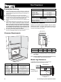
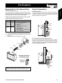
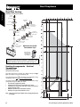
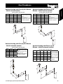
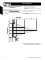
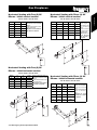
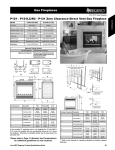
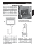
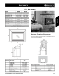
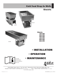
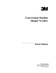
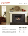
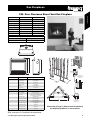
Gas Fireplaces
P48 Gas Fireplace
P48 Zero Clearance Direct Vent Gas Fireplace
P48-NG2
P48-LP2
Fuel Type
Natural Gas
Propane
5” W.C. (1.25 kPa)
12” W.C. (3.00 kPa)
Minimum Supply Pressure
Manifold Pressure - High
3.8” W.C. (0.95 kPa)
11” W.C. (2.74 kPa)
Manifold Pressure - Low
1.1” W.C. (0.27 kPa)
3.3” W.C. (0.82 kPa)
Orifice Size
#27 DMS - 0-4500ft
#47 DMS
Minimum Input
29,000 BTU/h (8.49 kW)
26,000 BTU/h (3.07 kW)
Maximum Input
51,000 BTU/h (14.94 kW)
48,000 BTU/h (6.30 kW)
5” Inner / 8” Outer
5” Inner / 8” Outer
Vent Sizing
Gas Fireplaces
Model
Approved Venting Systems
Flex Vent Systems:
FPI AstroCap™ Flex Vent
Rigid Pipe Vent Systems:
Simpson Dura-Vent® Direct Vent GS
B
A
L
C D
F
Top Header
Drywall
(or other
facing)
E
A
Unit Dimensions
Description
A
Front Face Width
B
Rear Firebox Width
C
Front Face Height
D
Height w/ Standoff
E
Unit Depth
H
11" (279mm)
dia. Hole through
wall Vent.
P33
48” (1219mm)
G
I
34-1/2” (876mm)
41” (1041mm)
M
47” (1193mm)
23-1/4” (324mm)
F
Firebox Height
Framing Dimensions
Description
40” (1016mm)
P33
G
Framing Width
48-1/2” (1232mm)
H***
Framing Height***
J
47-1/2” (1207mm)***
29-3/4” (756mm) Vertical Rise
26-1/4” (667mm) No Vertical Rise
I
Framing Depth
J
Corner Wall Length
K
Corner Facing Wall Width
L
Framed Chase Ceiling
N/A - Vertical Rise
50” (1270mm) No Vertical Rise
M
Vent Centerline Height
43” (1092mm)
N
Gas Connection Height
O
Gas Connection Inset
3-3/4” (95mm)
P
Gas Connection Width
5” (127mm)
N
57-5/8” (1464mm)
81-1/2” (2070mm)
K
O P
Opening for gas
connection
2” (51mm)
Please refer to Page 11 (Exterior Vent Terminations)
for additional guidelines on vent locations.
***Important: Framing height requires consideration of the hearth
depth. Dimension H = H + the thickness of installed hearth.
June 2007 Regency Product Specifications Book
61
Gas Fireplaces
Framing and Finishing
Vent Clearances
Clearance Dimension
1)
Horizontal - Top
2-1/2” (64mm)
Horizontal - Side
1-1/2” (38mm)
Horizontal - Bottom
1-1/2” (38mm)
Vertical
1-1/4” (32mm)
2)
3)
4)
5)
6)
Determine the total thickness of facing material (e.g. drywall plus
ceramic tiles) to allow the finished surface to be flush with the front
of the unit. Total facing thickness can vary from 1/2” (13mm) to 1-¼”
(32mm) thick.
Frame in the enclosure for the unit with framing material.
For exterior walls, insulate the enclosure to the same degree as
the rest of the house, apply vapor barrier and drywall, as per local
installation codes. (Do not insulate the fireplace itself.)
The top of the unit must not be closer than 39” (990mm) to the
ceiling.
Combustible material may be brought up to the top and
sides of the unit and be covered with ceramic tiles, bricks,
rock or other suitable combustible finishing materials.
Note: The unit does not have to be completely enclosed in a
chase. The clearance on top of the unit is 0” to the standoffs
so combustible building materials can be laid directly on top
of the standoffs. You must maintain proper clearances from
the vent to combustible materials (See Below).
Use metal studs for framing where the minimum clearance from
the vent to combustible material cannot be maintained.
WARNING
Failure to maintain required clearances is a major cause of
chimney related fires. Installation of this fireplace must comply
with these clearances.
Combustible Mantels
Because of the extreme heat this fireplace emits, the mantel
clearances are critical. Combustible mantel clearances from top of
the louvers are shown in the diagram below. Mantel may be installed
anywhere in the shaded area or higher.
Mantel Clearances
12 10
Clearance Requirements
8
6
4
0
2
12" (305mm)
Drywall
5 ½” (140mm)
Header
3 ½" (89mm)
B
C
D
Standoff
D
C
0
Top of
Louvers
A
A
Side View
F
Mantel Clearances
B
Front
A
B
C
D
41” (1041mm)
15” (381mm)
10” (254mm)
8” (203mm)
B
Note: If desired a non-combustible mantel may be installed at a
lower height.
Note: Ensure the paint that is used on the mantel and the facing
is “heat resistant” or the paint may discolour.
E
Mantel Leg Clearances
Combustible mantel leg clearances as per diagram below:
Clearances are from the finished edge of the unit
Measured From:
8” (203mm)
Minimum (Additional on this page)
B: Sidewall
6” (152mm)
C: Ceiling
36” (914mm)
Side of installed front
Top of installed unit
D: Mantel Depth
12” (305mm)
Maximum (Additional on this page)
E: Alcove Width
60” (1524mm)
Sidewall to Sidewall (Minimum)
F: Alcove Depth
36” (914mm)
Front to back wall (Maximum)
Side Wall (Min 6”)
P48
Maximum
1-½” projection at 3”
minimum clearance.
3”
Dimension
Mantel leg
A: Mantel Height
1-1/2"
Clearance:
Mantel leg
Gas Fireplaces
P48 Gas Fireplace
3”
Top of Hearth must not be higher than the base of the firebox.
6”
Allowable mantel leg
projection.
62
June 2007 Regency Product Specifications Book
Gas Fireplaces
P48 Gas Fireplace
Regency Direct Vent System (Flex)
Snorkel Terminations
These venting systems, in combination with the P48 Direct Vent Gas
Fireplace, have been tested and listed as a direct vent heater system
by Warnock Hersey. The location of the termination cap must conform
to the requirements in the Vent Terminal Locations diagram.
Snorkel Terminations:
For installations requiring a vertical rise on the exterior of the building, 14inch and 36-inch tall Snorkel Terminations are available. Follow the same
installation procedures as used for standard Horizontal Termination.
NEVER install the snorkel upside down.
FPI Direct Vent (Flex) System Termination Kits include all the parts
needed to install the P48 using a flexible vent.
FPI Kit #
Length
Contains:
#946-618
6 Feet
1)
2)
3)
4)
5)
6)
7)
8)
9)
10)
#946-616
10 Feet
6-5/8” flexible liner (Kit length)
4” flexible liner (Kit length)
spring spacers (3)
thimble (2)
AstroCap termination cap (1)
screws (12)
tube of Mill Pac (1)
plated screws (8)
S.S. screws #8 x 1-1/2” drill point, (4)
vinyl siding standoff
Dura-Vent
Snorkel
Min. 12"*
(305mm)
Notes:
1) Liner sections should be continuous without any joints or seams.
2) Only Flex pipe purchased from Regency may be used for Flex
installations.
3) Horizontal sections must be supported every 3 feet.
AstroCap XL
(Part# 946-623/P)
Vinyl Siding
Standoff
Wall Thimble
Below Grade Snorkel Installation (Dura-Vent Only)
If the Snorkel Termination must be installed below grade, i.e. basement
application, proper drainage must be provided to prevent water from
entering the Snorkel Termination. Refer to Rigid Pipe Installation
instructions for details. Do not attempt to enclose the Snorkel within the
wall, or any other type of enclosure.
5” dia.
Flue pipe
8" dia.
Flue pipe
Spring Spacer
Min. 12"*
(305mm)
Dura-Vent
Snorkel
Alternate Horizontal
Termination Caps
Alternate Snorkel
Termination Cap
Part #1282 (14”)
Part #1281 (36”)
Window
Well
Adequate
drainage
If required by the external termination location the listed
alternate termination caps may be used. (Refer to Page 11)
June 2007 Regency Product Specifications Book
Gravel
63
Gas Fireplaces
Horizontal Terminations Only
Gas Fireplaces
P48 Gas Fireplace
Rigid Pipe Venting
Gas Fireplaces
Horizontal or Vertical Terminations
Vertical
Terminal
0
2
4
8
6
10
12
14
Storm Collar
Vinyl Siding
Standoff
Flashing
40
Horizontal
Termination Cap
# 946-623/P
Ceiling Firestop
38
Maximum: 40 ft. (12.2m)
Wall Thimble
36
Adj.Pipe Length
11" - 14-5/8”
Pipe Length
90o Elbow
0
2
4
6
8
10
12
Horizontal
Termination Cap
# 946-623/P
34
24" Length
Vinyl Siding
Standoff
40
32
Wall Thimble
30
Adj.Pipe Length
11" - 14-5/8”
38
45o Elbow
36
2
4
6
8
28
10
Rigid Pipe Adapter
# 770-994
34
12
Alternate Horizontal
Termination Caps
26
24
Alternate Snorkel
Termination Cap
Part #1282 (14”)
Part #1281 (36”)
32
22
26
20
18
24
Venting Arrangements - Vertical
Terminations
22
Rigid Pipe System
(Propane & Natural Gas)
20
The P48 is approved for a maximum 40 ft. straight vertical, with Rigid
Pipe vent systems for Propane and Natural Gas.
18
The lightly shaded area,
, in the diagram shows allowable venting
configurations with a maximum two 45° elbows allowed.
10
16
The darker shaded area,
, in the diagram shows allowable venting
configurations using 45° and one 90° elbow.
8
14
•
•
•
6
12
10
•
•
Vent must be supported at offsets.
Horizontal sections must be supported every 3 feet.
Firestops are required at each floor level and whenever
passing through a wall.
Maintain clearances to combustible materials.
Minimum of 1’ pipe section between elbows.
Note: Must use optional flue adapter when using Rigid Pipe (Part
# 770-994).
8
Maximum: 27 ft. (8.2m)
If required by the external termination location the listed
alternate termination caps may be used. (Refer to Page 11)
16
14
12
4
Minimum 10’6” (3.2m)
28
Minimum 8’6” (2.6m)
30
Vertical Height (Feet)
0
2
0
Minimum 12” (305mm)
Max. 10’ (3m)(centerline to centerline)
6
4
64
June 2007 Regency Product Specifications Book
16
18
Gas Fireplaces
P48 Gas Fireplace
Vertical Venting with Three (3) 90°
Elbows - Initial vertical section.
Two 45° elbows = One 90° elbow
Option
V
H
V+ V1
A)
1’ Min.
4’ Max.
2’ Min.
B)
2’ Min.
5’ Max.
3’ Min.
C)
3’ Min.
6’ Max.
4’ Min.
D)
4’ Min.
7’ Max.
5’ Min.
E)
5’ Min.
8’ Max.
6’ Min.
Maximum total pipe: length, of
all sections, must not exceed
30 feet.
Total horizontal sections must
not exceed 8 feet.
Minimum of 1 foot between
90° elbows is required.
Vertical Venting with Two (2) 90° Elbows
- Initial horizontal section.
Two 45° elbows = One 90° elbow
Option
H + H1
V
A)
2’ Max.
2’ Min.
B)
3’ Max.
3’ Min.
C)
4’ Max.
4’ Min.
D)
5’ Max.
5’ Min.
E)
6’ Max.
6’ Min.
Maximum total pipe: length, of
all sections, must not exceed
30 feet.
Total horizontal sections must
not exceed 6 feet.
Minimum of 1 foot between
90° elbows is required.
June 2007 Regency Product Specifications Book
Two 45° elbows = One 90° elbow
Option
V
H + H1
V+ V1
A)
2’ Min.
3’ Max.
4’ Min.
Maximum total pipe: length, of
all sections, must not exceed
30 feet.
Total horizontal sections must
not exceed 8 feet.
Minimum of 1 foot between
90° elbows is required.
B)
3’ Min.
4’ Max.
6’ Min.
C)
4’ Min.
5’ Max.
7’ Min.
D)
5’ Min.
6’ Max.
8’ Min.
E)
6’ Min.
7’ Max.
9’ Min.
F)
7’ Min.
8’ Max.
10’ Min.
Vertical Venting with Three (3) 90°
Elbows - Initial horizontal section.
Two 45° elbows = One 90° elbow
Option
H
V
H + H1
V+ V1
A)
1’ Max.
1’ Min.
3’ Max.
3’ Min.
B)
2’ Max.
2’ Min.
4’ Max.
5’ Min.
C)
3’ Max.
3’ Min.
5’ Max.
7’ Min.
D)
4’ Max.
4’ Min.
6’ Max.
9’ Min.
E)
5’ Max.
5’ Min.
7’ Max.
11’ Min.
Maximum total pipe:
length, of all sections,
must not exceed 30
feet.
Total horizontal sections
must not exceed 7
feet.
Minimum of 1 foot
between 90° elbows
is required.
65
Gas Fireplaces
Vertical Venting with Two (2) 90° Elbows
- Initial vertical section.
Gas Fireplaces
Venting Arrangements - Horizontal
Terminations
•
•
•
This diagram shows all allowable combinations of vertical runs with
horizontal terminations, using one 45° and one 90° elbow (two 45º
elbows equal one 90° elbow).
Maintain clearances to combustibles.
Horizontal vent must be supported every 3 feet.
Firestops are required at each floor level and whenever passing
through a wall.
A vent guard should be used whenever the termination is lower than the
specified minimum or as per local codes.
Note: Must use optional flue adapter (Part # 770-994) when using
Rigid Pipe.
Note: FPI Direct Vent System (Flex) is only approved for horizontal
terminations.
Horizontal (Feet)
0
2
4
6
8
10
12
14
16
18
20
16
14
12
Vertical Height (Feet)
Gas Fireplaces
P48 Gas Fireplace
10
8
6
4
2
43” (1092mm)
Minimum
Height
Requirement
0
Please refer to Page 11 (Exterior Vent Terminations)
for additional guidelines on vent locations.
66
June 2007 Regency Product Specifications Book
Gas Fireplaces
P48 Gas Fireplace
Horizontal Venting with Three (3) 90°
Elbows - Initial vertical section.
Two 45° elbows = One 90° elbow
Option
V
H+ H1
A)
1’ Min.
3’ Max.
B)
2’ Min.
4’ Max.
C)
3’ Min.
5’ Max.
D)
4’ Min.
6’ Max.
E)
5’ Min.
7’ Max.
F)
6’ Min.
8’ Max.
Maximum total pipe: length, of
all sections, must not exceed
30 feet.
Total horizontal sections must
not exceed 8 feet.
Minimum of 1 foot between
90° elbows is required.
Two 45° elbows = One 90° elbow
Option
V
H
V+ V1
H + H1
A)
2’ Min.
1’ Max.
3’ Min.
4’ Max.
B)
3’ Min.
2’ Max.
4’ Min.
5’ Max.
C)
4’ Min.
3’ Max.
6’ Min.
6’ Max.
D)
5’ Min.
4’ Max.
8’ Min.
7’ Max.
E)
6’ Min.
5’ Max.
10’ Min.
8’ Max.
F)
7’ Min.
6’ Max.
12’ Min.
9’ Max.
Maximum total
pipe: length, of
all sections, must
not exceed 30
feet.
Total horizontal
sections must not
exceed 8 feet.
Minimum of 1
foot between
90° elbows is
required.
Horizontal Venting with Two (2) 90°
Elbows - Initial horizontal section.
Two 45° elbows = One 90° elbow
Option
H
V
H + H1
A)
1’ Max.
1’ Min.
3’ Max.
B)
2’ Max.
2’ Min.
5’ Max.
C)
3’ Max.
4’ Min.
6’ Max.
D)
4’ Max.
6’ Min.
7’ Max.
E)
5’ Max.
8’ Min.
8’ Max.
Maximum total pipe: length, of
all sections, must not exceed
30 feet.
Total horizontal sections must
not exceed 8 feet.
Minimum of 1 foot between
90° elbows is required.
June 2007 Regency Product Specifications Book
Horizontal Venting with Three (3) 90°
Elbows - Initial horizontal section.
Two 45° elbows = One 90° elbow
Option
H
V
A)
1’ Max.
1’ Min.
B)
2’ Max.
3’ Min.
C)
3’ Max.
5’ Min.
D)
4’ Max.
7’ Min.
E)
5’ Max.
9’ Min.
F)
6’ Max.
11’ Min.
H + H1 + H2 Maximum total pipe:
length, of all sections,
3’ Max.
must not exceed 30
feet.
5’ Max.
Total horizontal sections
must not exceed 7
6’ Max.
feet.
Minimum of 1 foot
7’ Max.
between 90° elbows
is required.
8’ Max.
9’ Max.
67
Gas Fireplaces
Horizontal Venting with Two (2) 90°
Elbows - Initial vertical section.