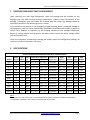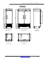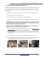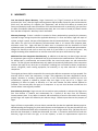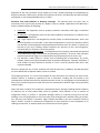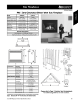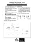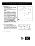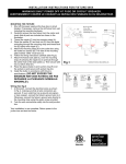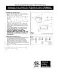
1
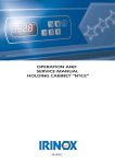
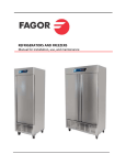
REACH IN REFRIGERATORS & FREEZERS Manual for installation, use and maintenance REACH IN OPERATIONS AND SERVICE MANUAL/ Rev. Jul-11 TABLE OF CONTENTS 1 RECEIVING AND INSPECTING THE EQUIPMENT ___________________________________ 3 2 SPECIFICATIONS ___________________________________________________________ 3 2.1 3 DIMENSIONS ________________________________________________________ 5 INSTALLATION ____________________________________________________________ 9 3.1 UNCRATING _________________________________________________________ 9 3.2 LOCATION __________________________________________________________ 9 3.3 DATA PLATE _________________________________________________________ 9 3.4 INSTALLATION OF CASTORS OR OPTIONAL LEGS ___________________________ 10 3.5 LEVELING __________________________________________________________ 11 3.6 ELECTRICAL CONNECTIONS ____________________________________________ 11 3.7 SHELVING INSTALLATION _____________________________________________ 12 4 OPERATION______________________________________________________________ 12 5 MAINTENANCE ___________________________________________________________ 15 6 TROUBLE SHOOTING ______________________________________________________ 17 7 WIRING DIAGRAMS _______________________________________________________ 18 8 WARRANTY ______________________________________________________________ 24 For Customer Service: Call 1-866-GO FAGOR – www.fagorcommercial.com Page 2 REACH IN OPERATIONS AND SERVICE MANUAL/ Rev. Jul-11 1 RECEIVING AND INSPECTING THE EQUIPMENT Upon receiving your new Fagor Refrigerator, check the package and the machine for any damages that may have occurred during transportation. Visually inspect the exterior of the package, if damaged, open and inspect the contents with the carrier. Any damage should be noted and reported on the delivering carrier’s receipt. In the event that the exterior is not damaged, yet upon opening, there is concealed damage to the equipment notify the carrier immediately. Notification should be made verbally as well as in written form. Request an inspection by the shipping company of the damaged equipment. Retain all crating material until inspection has been made. Contact the dealer through which you purchased the unit. Check the compressor compartment housing and visually inspect the refrigeration package. Be sure lines are secure and base is still intact. 2 SPECIFICATIONS REACH IN REFRIGERATORS AND FREEZERS, GENERAL SPECS Model Capac. # of BTU'S Temperature Operation Pressure in (Cu.Ft.) Shvls /Hr Set Point Cut in Suction Line * SuperHeat ** Ref. Amount Ref. Type Ship Weight QR-1 23 3 1666 0°C / 32°F 5°C / 41°F 12-14 PSIG 7°C / 13°F 11.6 oz 134a 295 QR-2 49 6 2104 0°C / 32°F 5°C / 41°F 12-14 PSIG 7°C / 13°F 11.2 oz 134a 475 QF-1 23 3 2493 -22°C / -8°F -18°C / 0°F 16-18 PSIG 4°C / 7°F 14.1 oz 404A 295 QF-2 49 6 3644 -22°C / -8°F -18°C / 0°F 16-18 PSIG 4°C / 7°F 23.9 oz 404A 475 QR-1G 23 3 1666 0°C / 32°F 5°C / 41°F 12-14 PSIG 7°C / 13°F 12.3 oz 134a 295 QR-2G 49 6 2104 0°C / 32°F 5°C / 41°F 12-14 PSIG 7°C / 13°F 11.2 oz 134a 475 QVR-1 21 3 1666 0°C / 32°F 5°C / 41°F 12-14 PSIG 7°C / 13°F 11.6 oz 134a 295 QVR-2 45 6 2104 0°C / 32°F 5°C / 41°F 12-14 PSIG 7°C / 13°F 11.2 oz 134a 475 QVF-1 21 3 2493 -22°C / -8°F -18°C / 0°F 16-18 PSIG 4°C / 7°F 14.1 oz 404A 295 QVF-2 45 6 3644 -22°C / -8°F -18°C / 0°F 16-18 PSIG 4°C / 7°F 23.9 oz 404A 475 QVR-1G 21 3 1666 0°C / 32°F 5°C / 41°F 12-14 PSIG 7°C / 13°F 12.3 oz 134a 295 QVR-2G 45 6 2104 0°C / 32°F 5°C / 41°F 12-14 PSIG 7°C / 13°F 11.2 oz 134a 475 Note: * The pressure in the suction line is recommended at 32°C/90°F maximum of ambient temperature. ** Superheat measured in the outlet of the evaporator at 32°C/90°F For Customer Service: Call 1-866-GO FAGOR – www.fagorcommercial.com Page 3 REACH IN OPERATIONS AND SERVICE MANUAL/ Rev. Jul-11 Model QR-1 REACH IN REFRIGERATORS AND FREEZERS, ELECTRICAL SPECS Max. NEMA Breaker Wire gauge recommended for 2% voltage drop in supply circuits ** Amps HP Voltage Plug 60 ft 80 ft 100 ft 120 ft 140 ft Size* 40 ft *** 5.6 1/4 115 / 60 / 1 5-15P 15 amp 14 AWG 14 AWG 12 AWG 12 AWG 12 AWG 10 AWG QR-2 6.9 1/3 115 / 60 / 1 5-15P 15 amp 14 AWG 12 AWG 12 AWG 10AWG 10 AWG 10 AWG QF-1 QF-2 QR-1G 8.5 12.9 5.8 3/4 115 / 60 / 1 5-15P 15 amp 14 AWG 1 115 / 60 / 1 5-15P 20 amp 12 AWG 1/4 115 / 60 / 1 5-15P 15 amp 14 AWG 12 AWG 10 AWG 14 AWG 10 AWG 8 AWG 12 AWG 10 AWG 8 AWG 12 AWG 8 AWG 8 AWG 10 AWG 8 AWG 6 AWG 10 AWG QR-2G QVR-1 QVR-2 QVF-1 QVF-2 QVR-1G QVR-2G 7.2 5.6 6.9 8.5 12.9 5.8 7.2 1/3 1/4 1/3 3/4 1 1/4 1/3 12 AWG 14 AWG 12 AWG 12 AWG 10 AWG 14 AWG 12 AWG 12 AWG 12 AWG 12 AWG 10 AWG 8 AWG 12 AWG 12 AWG 10 AWG 12 AWG 10 AWG 10 AWG 8 AWG 12 AWG 10 AWG 10 AWG 12 AWG 10 AWG 8 AWG 8 AWG 10 AWG 10 AWG 8 AWG 10 AWG 10 AWG 8 AWG 6 AWG 10 AWG 8 AWG 115 / 60 / 1 115 / 60 / 1 115 / 60 / 1 115 / 60 / 1 115 / 60 / 1 115 / 60 / 1 115 / 60 / 1 5-15P 5-15P 5-15P 5-15P 5-15P 5-15P 5-15P 15 amp 15 amp 15 amp 15 amp 20 amp 15 amp 15 amp 14 AWG 14 AWG 14 AWG 14 AWG 12 AWG 14 AWG 14 AWG Note: * Breaker sizes are recommended by the manufacturer to protect the equipment by over load; this breaker only must be dedicated for the equipment. ** If the equipments are installed far away of the circuit breaker, these are the wire gauge recommend to connect the appliance; if the distance is higher that the chart values, please contact an electrician. *** Distance in feet from the breaker or the power supply to the appliance. For Customer Service: Call 1-866-GO FAGOR – www.fagorcommercial.com Page 4 REACH IN OPERATIONS AND SERVICE MANUAL/ Rev. Jul-11 2.1 DIMENSIONS MODEL´S: Q´S 553 16 [1402mm] 311 8 [790mm] 275 8 [702mm] 57 5 8 [1464m m] 795 8 [2023mm] 845 8 [2149mm] 5 [126mm] 5 [126mm] 497 16 [1255mm] 237 8 [606mm] FRONT VIEW Q’S-1 FRONT VIEW Q’S-2 SIDE VIEW Q’S-1 & Q’S-2 311 8 [790m m] 221 4 [565mm] 27 5 8 [702m m] TOP VIEW Q’S-1 311 8 [790mm ] 845 8 [2149mm] 795 8 [2023mm] 29 [736mm] 55 3 16 [1402m m] TOP VIEW Q’S-2 For Customer Service: Call 1-866-GO FAGOR – www.fagorcommercial.com Page 5 REACH IN OPERATIONS AND SERVICE MANUAL/ Rev. Jul-11 MODEL´S: QV´S 311 8 [790mm] 55 3 16 [1402mm] 275 8 [702mm] 57 5 8 [1464mm] 76 [1931mm] 81 [2057mm] 5 [126mm] 5 [126mm] 4971 6 [1255mm] 221 4 [565mm] FRONT VIEW QV’S-2 311 8 [790m m ] FRONT VIEW QV’S-1 27 5 8 [702m m ] TOP VIEW QV’S-1 237 8 [606mm] SIDE VIEW QV’S-1 & QV’S-2 311 8 [790m m ] 8015 16 [2056mm] 76 [1930mm] 29 [736mm] 55 3 16 [1402m m ] TOP VIEW QV’S-2 For Customer Service: Call 1-866-GO FAGOR – www.fagorcommercial.com Page 6 REACH IN OPERATIONS AND SERVICE MANUAL/ Rev. Jul-11 MODEL´S: Q´S-G 311 8 [790mm] 27 5 8 [702mm] 55 3 16 [1402mm] 575 8 [1464mm] 795 8 [2023mm] 845 8 [2149mm] 5 [126mm] 5 [126mm] 497 16 [1255mm] 221 4 [566mm] FRONT VIEW Q’S-2G 311 8 [790mm] FRONT VIEW Q’S-1G 27 5 8 [702mm] TOP VIEW Q’S-1G 237 8 [606mm] SIDE VIEW Q’S-1G & Q’S-2G 311 8 [790mm] 845 8 [2149mm] 79 5 8 [2023mm] 29 [736mm] 553 16 [1402mm] TOP VIEW Q’S-2G For Customer Service: Call 1-866-GO FAGOR – www.fagorcommercial.com Page 7 REACH IN OPERATIONS AND SERVICE MANUAL/ Rev. Jul-11 MODEL´S: QV´S-G 311 8 [790mm] 553 16 [1402mm] 27 5 8 [702mm] 575 8 [1464mm] 76 [1931mm] 5 [126mm] 81 [2057mm] 5 [126mm] FRONT VIEW QV’S-2G 311 8 [790mm] FRONT VIEW QV’S-1G 27 5 8 [702mm] TOP VIEW QV’S-1G 237 8 [606mm] 497 16 [1255mm] 221 4 [565mm] SIDE VIEW QV’S-1G & QV’S-2G 311 8 [790mm] 8015 16 [2056mm] 76 [1930mm] 29 [736mm] 553 16 [1402mm] TOP VIEW QV’S-2G For Customer Service: Call 1-866-GO FAGOR – www.fagorcommercial.com Page 8 REACH IN OPERATIONS AND SERVICE MANUAL/ Rev. Jul-11 3 INSTALLATION 3.1 UNCRATING Cut and remove the outer packaging. Cut the 4 clamps that hold the refrigerator to the skid. Lift the unit off the skid. If machine was laid down during this operation remember to leave the cabinet upright for 24 hours before plugging into power source. 3.2 LOCATION Units represented in this manual are intended for indoor use only. Be sure the location chosen has a floor strong enough to support the total weight of the unit and contents. For the most efficient operation, be sure to provide good air circulation inside and outside of the unit. Inside cabinet: The first cleaning must be made when you unpack the machine and before switching it on. You have to clean it with water and with mild detergent. When it is clean and dry, insert the accessories in the appropriate places, for the best use of the user. Outside cabinet: Be sure that the unit has access to ample air. Avoid hot corners and locations near stoves and ovens. It is recommended that the unit be installed no closer than 2” from any wall. The place where the refrigerator is placed must be open and clean, avoiding that the fan of the condensing unit absorbs materials which are deposited then into the condenser blades and coil, which can produce failures. 3.3 DATA PLATE The data plate in located inside the cabinet, near the top front left corner. Under no circumstances should the data plate be removed from the unit. The data plate is essential to identify the particular features of your machine and is of great benefit to installers, operators and maintenance personnel. It is recommended that, in the event the data plate is removed, you copy down the essential information in this manual for reference before installation. For Customer Service: Call 1-866-GO FAGOR – www.fagorcommercial.com Page 9 REACH IN OPERATIONS AND SERVICE MANUAL/ Rev. Jul-11 3.4 INSTALLATION OF CASTORS OR OPTIONAL LEGS To obtain maximum strength and stability of the unit, be sure that castors are secure and unit is level. Castors, as well as shims and tool to assembly the castors are supplied in a box inside the machine. The bearing race on the castor or the top edge of the leg must make firm contact with the rail. Steps: 1) Cut the 4 straps that hold the refrigerator to the pallet. 2 at the front and 2 at the back 2) Slide machine until castors holes are exposed. 3) Carefully lift that end of the unit high enough to install the casters 4) Repeat the same operation by rotating the machine to expose the other 2 castors holes CAUTION! NEVER LAY MACHINE ON ITS BACK! IF NEEDED LEAVE THE CABINET UPRIGHT FOR 24 HOURS BEFORE PLUGGING INTO POWER SOURCE. TO AVOID DAMAGE TO LOWER FRAME, SLOWLY RAISE UNIT TO UPRIGHT POSITION FAILURE TO MEET THIS REQUIREMENT CAN CAUSE COMPRESSOR FAILURE AND UNIT DAMAGE THAT WILL NOT BE COVERED UNDER WARRANTY! 5) Thread castors into the underside of the cabinet frame rail. FIG. 1. Castors with brake must go at the front. Castors w/o brake at the back of the unit. 6) For levelling, insert the shim between the castor and the frame rail. Install the desired number of shims; make sure the slot of the shim is in contact with the threaded stem of the castor. FIG.2 7) If more than one shim is used, turn the slot at a 90º angle so they are not in line 8) Turn the bearing race clockwise to tighten and secure the castor by tightening the anchoring bolt with a ¾ inch open-end wrench or the tool provided. FIG. 3 FIG. 1 FIG.2 For Customer Service: Call 1-866-GO FAGOR – www.fagorcommercial.com FIG. 3 Page 10 REACH IN OPERATIONS AND SERVICE MANUAL/ Rev. Jul-11 Optional legs are hand- tightened. Thread leg into cabinet bottom frame rail. The end of the leg is adjustable to easy levelling. Caution! To avoid damage to lower rail assembly, slowly raise unit to upright position Caution! When lifting unit remember to leave the cabinet upright for 24 hours before plugging into power source. Failure to meet this requirement can cause compressor failure and unit damage 3.5 LEVELING Set unit in its final location. A level cabinet looks better and will perform better. Effective condensate removal and door operation will be effected by levelling. Machine must be levelled front to back and side to side with a level. Casters include shims for levelling. Insert the shim between the castor and the frame rail. (See installation of castors). Lock front castors so cabinet doesn’t move. Ensure the drain hose or hoses (bottom rear side of the cabinet) are positioned in the pan. Free plug and cord (do not plug in yet) and place the unit close enough to the electrical supply so extension cords are never used. 3.6 ELECTRICAL CONNECTIONS Refer to the amperage data on this manual or on data plate and your local code or the National Electrical Code to be sure unit is connected to the proper power source. Verify correct incoming voltage according to the Data Plate information. A protected circuit of the correct voltage and amperage must be run for connection of the supply cord. Machine must be grounded and connected in accordance with NEC Article 422 Appliances. DANGER: Power must be turned off and disconnected from the power source whenever performing maintenance, repair or cleaning the condensing unit. If machine still running when power is off, disconnect power at the circuit breaker before unplugging the machine. WARNING: Machine and compressor warranties are void if failure is due to improper electrical installation. For Customer Service: Call 1-866-GO FAGOR – www.fagorcommercial.com Page 11 REACH IN OPERATIONS AND SERVICE MANUAL/ Rev. Jul-11 3.7 SHELVING INSTALLATION 1) Hook shelf rails onto shelf pilasters 2) Position all two shelf rails equal in distance from the floor for level shelves 3) Wire shelves are oriented so that cross support bars are facing down Note: Single door Reach-ins include an airflow guard on the rear of the shelves as well as a lip to maintain an air space at the rear of the cabinet 4) Place shelves on shelf clips making sure all corners are seated properly 4 OPERATION After plugging your appliance in at the power supply, set the ON/Off button in the ON position, now you should see the temperature in the display of the controller, the compressor and fan icon will be flashing by 3 minutes, after of this time the compressor will run. - Compressor Icon - Evaporator Fan Icon - Temperature inside the cabinet Verify you don't have any alarms in the temperature controller, if after turn ON the equipment the controller show you some alarm, take the number of this alarm, then call at the technical service, they will help you to fix the problem. Note: The controller of the equipment is programmed to show you the temperature in Fahrenheit degrees, to change to Celsius degrees see point 4.2. Description of Buttons in the Controller - To increase Set Point of Temperature. - To Turn On/Off the compressor without unplug the equipment (press and hold 3 seconds) - To Change the set point - To access at programming mode -To decrease Set Point of Temperature. -To force a manual defrost (press and hold 3 seconds) For Customer Service: Call 1-866-GO FAGOR – www.fagorcommercial.com Page 12 REACH IN OPERATIONS AND SERVICE MANUAL/ Rev. Jul-11 4.1 Changing the Set Point of the temperature in the controller. Already the controller has a set point of temperature programmed from the factory to assure the correctly function of the equipment (see the chart with general specs), if you wish, you can change the set point of temperature, for do this, follow the next steps Note: If you move the set point of temperature you also are affected the behavior of the equipment. You have limits to increase or decrease the set point of temperature to keep the correctly function of the equipment, any change in the parameters made by the user different from factory configuration, are under costumer responsibility. 1.-Push the SET button for 1 second, then you should see a flashing number, release the button 2.-If you want increase the value of the set point for a new temperature, press the button UP arrow (see the picture below), press this button to reach the wish value, release the button and then press the SET button to keep and save the new value. Note: The maximum value you can set in the controller is: For refrigerators: 5°C (40°F) For freezers: -16°C (2°F) 3.- Or, if you wish decrease the value of the set point for a new temperature, press the button DOWN arrow (see the picture below), press this button to reach the desired value, release the button and then press the SET button to keep and save the new value. Note: The minimum value you can set in the controller is: For refrigerators: -1°C (30°F) For freezers: -23°C (9°F) For Customer Service: Call 1-866-GO FAGOR – www.fagorcommercial.com Page 13 REACH IN OPERATIONS AND SERVICE MANUAL/ Rev. Jul-11 4.2 Changing the reading temperature from °F to °C or vice versa To change the reading of the temperature from °F to °C or vice versa, you need access at the programming mode in the controller, to do this, press and hold the SET button for 5 seconds until see the “PS” in the display, release the button, press just one time the SET button, now you will see the number “0” (cero), with the button UP arrow set a value of “22”, then press the SET button, you will see the “PS” again, now with the button DOWN arrow find the parameter “EZY”, press just one time the SET button, now you will see a number, for example “1, 2, 3 or 4”, with the button UP or DOWN arrow set a value according at the charts For Refrigerators Temperature in °F Temperature in °C EZY Value Application 3 Refrigeration 4 Refrigeration For Freezers EZY Value Application Temperature in °F 1 Freezer Temperature in °C 2 Freezer Temperature in °F 3 Refrigeration Temperature in °C 4 Refrigeration Note: The freezer equipment can be used like a refrigerator if you wish, just select the value of the parameter “EZY” according at the chart above. The refrigerators never must be used like a freezer. After you chose the value for the EZY parameter, press and hold the SET button for 5 seconds, now you will see the temperature in the display in °F or °C according at your election. Other functions: 4.3 Manual Defrost The manual defrost can be used in a necessary case, for do this, hold the button Down arrow for 5 seconds, then you will see in the display of the controller a snowflake icon (showed in bottom left side of the temperature indicator), this indicate that the equipment is in Defrost mode. For exit of manual defrost, hold the button down arrow for 5 seconds, the snowflake icon will turn off, wait 2 min for the compressor start. Note: If the equipment doesn’t reach the temperature, first verify that the controller doesn’t been in defrost mode, you can check this if the snowflake icon is showed turn on in the display, remember, the controller will have defrost each 6 hrs by 25 min of duration. To end the defrost follow the previously step or unplug the equipment from the power supply. Please be sure that modifications on the control has been done by a specialized technical staff or if you have any questions please contact your technical support. If the control haven’t set upped correctly this could be damage and the warranty will not be covered by manufacturer. For Customer Service: Call 1-866-GO FAGOR – www.fagorcommercial.com Page 14 REACH IN OPERATIONS AND SERVICE MANUAL/ Rev. Jul-11 5 MAINTENANCE Stainless Steel Care and Cleaning Proper cleaning of stainless steel requires soft cloths or plastic souring pads. Never use steel pads, wire brushes or scrapers! Cleaning solutions need to be alkaline or non-chloride cleaners. Any cleaner containing chlorides will damage the protective film of the stainless steel. Chlorides are also commonly found in hard water, salts, and household and industrial cleaners. If cleaner containing chlorides are used be sure to rinse repeatedly and dry thoroughly upon completion. Routine cleaning of stainless steel can be done with soap and water. Extreme stains or grease should be cleaned with a non-abrasive cleaner and plastic scrub pad. There are also stainless steel cleaners available which can restore and preserve the finish of the steels protective layer. Never use and acid based cleaning solution! Many food products have an acidic content which can deteriorate the finish. Be sure to clean the ALL food products from any stainless steel surface. Common items include peppers, tomatoes and other vegetables. Cleaning the Condenser Coil DANGER: Power must be turned off and disconnected from the power source whenever performing maintenance, repair or cleaning the condensing unit. Disconnect machine. Remove front bottom panel and carefully slide out the condensing unit. The condenser coil requires regular cleaning; recommended is every 30-60 days, depending of the accumulation of dust and grease. If the build up on the coil consists of only light dust and debris the condenser coil can be cleaned with a simple brush. Heavier dust build up may require a vacuum or even compressed air to blow though the condenser coil. If heavy grease is present there are de-greasing agents available for refrigeration use and specifically for the condenser coils. The condenser coil may require a spray with the de-greasing agent and then blown through with compressed air. Be sure all electrical and mechanical parts are dry before turning on the power. Never use a high pressure water wash for this cleaning procedure as water can damage the electrical components located near or at the condenser coil. Do not place filter material in front of condenser coil. This material blocks air-flow to the coil similar to having a dirty coil! For Customer Service: Call 1-866-GO FAGOR – www.fagorcommercial.com Page 15 REACH IN OPERATIONS AND SERVICE MANUAL/ Rev. Jul-11 If you keep the Condenser clean you will minimize your service expense and lower your electrical costs. Failure to maintain a clean condenser coil can initially cause high temperatures and excessive run times. Continuous operation with dirty or clogged condenser coils can result in compressor failures. Neglecting the condenser coil cleaning procedures WILL VOID YOUR WARRANTY associated with the compressor or cost to replace the compressor! To put back the condensing unit in its place, slide in the unit carefully. BE SURE DRAIN PIPE IS LOCATED OVER THE PAN. Replace front bottom panel. Gasket Maintenance Gaskets require regular cleaning to prevent mold and mildew build up and also to keep the elasticity of the gasket. Gasket cleaning can be done with the use of warm soapy water. Avoid full strength cleaning products on gaskets as this can cause them to become brittle and prevent proper seals. Also, never use sharp tools or knives to scrape or clean the gasket which could possibly tear the gasket and rip the bellows. Gaskets can easily be replaced and do not require the use of tools or authorized service persons. The gaskets can be pulled out of the grove in the door and new gaskets can be “pressed” back into place. Doors/Hinges Over time and with heavy use doors the hinges may become loose. If it is noticed that the door is beginning to sag, it may become necessary to tighten the screws that mount the hinge brackets to the frame of the unit. If the doors are loose or sagging this can cause the hinge to pull out of the frame which may damage both the doors and the door hinges. In some cases this can require qualified service agents or maintenance personnel. Drain Maintenance Each unit has a drain located inside the unit which removes the condensation from the evaporator coil and evaporates it at an external condensate evaporator pan. Each drain can become loose or disconnected from moving or bumping the drain. IF YOU NOTICE EXCESSIVE WATER ACCUMULATION ON THE INSIDE OF THE UNIT be sure the drain tube is connected from the evaporator housing to the condensate evaporator drain pan. IF WATER IS COLLECTED UNDERNEATH THE UNIT you may want to check the condensate evaporator drain tube to be sure it is still located inside the drain pan. The levelling of the unit is important as the units are designed to drain properly when on a level surface, if your floor is not For Customer Service: Call 1-866-GO FAGOR – www.fagorcommercial.com Page 16 REACH IN OPERATIONS AND SERVICE MANUAL/ Rev. Jul-11 level this can also cause drain problems. Be sure all drain lines are free of obstructions; typically food product is found blocking drain lines causing water to back up and overflow the drain pans. 6 TROUBLE SHOOTING Sometimes, working failures are due to simple causes which can be solved by the user. Before asking for the help of a qualified technician, you have to do some verification. These failures are not covered by the warranty: 1) Refrigerator doesn’t work a. Check out that machine is still connected b. Check out ON/OFF button is at ON position. 2) Refrigerator doesn’t reach temperature a. Check out that the thermostat is not in OFF position b. Check out that machine is not on defrost cycle c. Ensure Equipment is in a ventilated place and removed min. 2” from any other appliance or heat source d. The environment maximum temperature must be 38ºC / 100 ºF e. To insure proper air flow, product must not be placed higher than the maximum level mark located on the internal wall of the unit f. If FREEZER, check out temperature is not Celsius g. Check out that gasket is in good conditions and door is sealed h. Check out fan is moving. Open the door and press and hold door switch for verification i. Don’t put any food inside up to Reach in is at temperature j. If FREEZER, food must be previously frozen before going to the cabinet k. Be sure castors or legs were installed l. If FREEZER, end user must defrost unit and wait if afterwards unit works 3) There is water inside the refrigerator a. Check out that drain pan inside the cabinet is in position b. Check out that there is not food clogging the drain line. 4) There is water under the refrigerator a. Check out that the drain pipe is over the pan b. Check out cabinet is level Warning: To assure proper operation of equipment it is recommended that the unit is on for 8 hours prior to the introduction of perishables. For Customer Service: Call 1-866-GO FAGOR – www.fagorcommercial.com Page 17 REACH IN OPERATIONS AND SERVICE MANUAL/ Rev. Jul-11 7 WIRING DIAGRAMS QR – 1 & QR-1G Color Estándar / Standard Calibre AWG (AWG Size) Color Ref. Símbolo /Symbol Descripción/Description Símbolo /Symbol Descripción/Description A VE Ventilador de Evaporador/Evaporator's Fan RDE Resistencia de Descarche/Defrost Resistance COM Compresor/Compressor RG Resistencia de Desague/Drain Resistance 18 AWG Verde/Green Azul Obscuro/Dark Blue 16 AWG B Marrón/Brown 16 AWG C VC Ventilador de Condensador/Condenser Fan CONT Contactor/Auxiliar Contactor Azul Claro/Light Blue 18 AWG D LAM Lampara/Light JB Araña de Conexiónes/Juction Box Marrón/Brown 18 AWG E CE Controlador Eléctronico/Electronic Controller TA Termostato Mécanico/Thermostat T1 Sensor de Ambiente/ Environment Sensor Azul Obscuro/Dark Blue 18 AWG F MP Micro-interruptor Puerta/Door Micro-Switch Amarillo/Yellow 18 AWG G INT Interruptor Principal/Main Switch T2 Sensor Deshielo/ Defrost Sensor Rojo/Red 18 AWG H RM Resistencia de Marco/Frame Resistance INT-L Interruptor Lámpara/Ligth Switch Negro/Black 16 AWG I Blanco/White 18 AWG J Blanco/White 14 AWG K Negro/Black 14 AWG L Negro Rayado/Black Striped 14 AWG M LINEA/LINE CE VE NEUTRO/NEUTRE CE CAREL PJEZ-C VE COM/VC RDE L G LINEA/LINE C I E NTC/PTC PROBES N CAREL PJEZ-C RDE COM/VC L JB B T1 NEUTRO/NEUTRE G H C I NTC/PTC PROBES N E JB B T2 T1 L L M M L COM T2 K L L M M L COM A A C C L I INT VC K A C L I INT E B MP MP G 3 2 1 NC NA COM J LAM F VE 2 3 1 NC NA COM A B F B B INT-L A E G F J LAM B A VE B Piloto A B QR-1 For Customer Service: Call 1-866-GO FAGOR – www.fagorcommercial.com VC K A C E B F K QR-1G Page 18 REACH IN OPERATIONS AND SERVICE MANUAL/ Rev. Jul-11 QR – 2 & QR-2G Color Estándar / Standard Calibre AWG (AWG Size) Color Ref. Símbolo /Symbol Descripción/Description Símbolo /Symbol Descripción/Description Verde/Green 18 AWG A VE Ventilador de Evaporador/Evaporator's Fan RDE Resistencia de Descarche/Defrost Resistance Azul Obscuro/Dark Blue 16 AWG B COM Compresor/Compressor RG Resistencia de Desague/Drain Resistance Marrón/Brown 16 AWG C VC Ventilador de Condensador/Condenser Fan CONT Contactor/Auxiliar Contactor Azul Claro/Light Blue 18 AWG D LAM Lampara/Light JB Araña de Conexiónes/Juction Box Marrón/Brown 18 AWG E CE Controlador Eléctronico/Electronic Controller TA Termostato Mécanico/Thermostat T1 Sensor de Ambiente/ Environment Sensor Azul Obscuro/Dark Blue 18 AWG F MP Micro-interruptor Puerta/Door Micro-Switch Amarillo/Yellow 18 AWG G INT Interruptor Principal/Main Switch T2 Sensor Deshielo/ Defrost Sensor Rojo/Red 18 AWG H RM Resistencia de Marco/Frame Resistance INT-L Interruptor Lámpara/Ligth Switch Negro/Black 16 AWG I Blanco/White 18 AWG J Blanco/White 14 AWG K Negro/Black 14 AWG L Negro Rayado/Black Striped 14 AWG M LINEA/LINE CAREL PJEZ-C VE VE C I NTC/PTC PROBES N E RDE COM/VC L JB CE B T1 NEUTRO/NEUTRE CAREL PJEZ-C CE COM/VC RDE L G LINEA/LINE NEUTRO/NEUTRE G C I NTC/PTC PROBES N E T1 T2 L M M L L COM JB B T2 L K L M M L COM A A I L I I B C C E E E B B MP MP MP F F B F F F B I INT INT MP B F F F B B G G VE VE F A F A INT-L J E J LAM F LAM B Piloto F RM B E RM RF B E B E RF E QR-2 For Customer Service: Call 1-866-GO FAGOR – www.fagorcommercial.com VC K A C B I E L K A C B VC C E I C E K B QR-2G Page 19 REACH IN OPERATIONS AND SERVICE MANUAL/ Rev. Jul-11 QVR – 1 & QVR-1G Color Estándar / Standard Calibre AWG (AWG Size) Color Verde/Green Ref. Símbolo /Symbol Descripción/Description Símbolo /Symbol Descripción/Description A VE Ventilador de Evaporador/Evaporator's Fan RDE Resistencia de Descarche/Defrost Resistance COM Compresor/Compressor RG Resistencia de Desague/Drain Resistance 18 AWG Azul Obscuro/Dark Blue 16 AWG B Marrón/Brown 16 AWG C VC Ventilador de Condensador/Condenser Fan CONT Contactor/Auxiliar Contactor Azul Claro/Light Blue 18 AWG D LAM Lampara/Light JB Araña de Conexiónes/Juction Box Marrón/Brown 18 AWG E CE Controlador Eléctronico/Electronic Controller TA Termostato Mécanico/Thermostat Azul Obscuro/Dark Blue 18 AWG F MP Micro-interruptor Puerta/Door Micro-Switch T1 Sensor de Ambiente/ Environment Sensor Amarillo/Yellow 18 AWG G INT Interruptor Principal/Main Switch T2 Sensor Deshielo/ Defrost Sensor Rojo/Red 18 AWG H RM Resistencia de Marco/Frame Resistance INT-L Interruptor Lámpara/Ligth Switch Negro/Black 16 AWG I Blanco/White 18 AWG J Blanco/White 14 AWG K Negro/Black 14 AWG L Negro Rayado/Black Striped 14 AWG M LINEA/LINE NEUTRO/NEUTRE CE CAREL PJEZ-S LINEA/LINE CE CAREL PJEZ-S COM/VC L C I E COM/VC NTC/PTC PROBES N NEUTRO/NEUTRE L N E B JB B C I NTC/PTC PROBES JB T1 L M M L L COM T1 K L M M L A L COM K A C L I INT VC C K C L I A E INT B MP MP 1 3 2 COM NA NC E G J J LAM G 1 3 2 COM NA NC B E VE G B A A INT-L G VE B E J LAM A B A Piloto B QVR-1 For Customer Service: Call 1-866-GO FAGOR – www.fagorcommercial.com K A C E B VC QVR-1G Page 20 REACH IN OPERATIONS AND SERVICE MANUAL/ Rev. Jul-11 QVR – 2 & QVR-2G Color Estándar / Standard Calibre AWG (AWG Size) Color Verde/Green Ref. Símbolo /Symbol Descripción/Description Símbolo /Symbol Descripción/Description A VE Ventilador de Evaporador/Evaporator's Fan RDE Resistencia de Descarche/Defrost Resistance COM Compresor/Compressor RG Resistencia de Desague/Drain Resistance 18 AWG Azul Obscuro/Dark Blue 16 AWG B Marrón/Brown 16 AWG C VC Ventilador de Condensador/Condenser Fan CONT Contactor/Auxiliar Contactor Azul Claro/Light Blue 18 AWG D LAM Lampara/Light JB Araña de Conexiónes/Juction Box Marrón/Brown 18 AWG E CE Controlador Eléctronico/Electronic Controller TA Termostato Mécanico/Thermostat Azul Obscuro/Dark Blue 18 AWG F MP Micro-interruptor Puerta/Door Micro-Switch T1 Sensor de Ambiente/ Environment Sensor Amarillo/Yellow 18 AWG G INT Interruptor Principal/Main Switch T2 Sensor Deshielo/ Defrost Sensor Rojo/Red 18 AWG H RM Resistencia de Marco/Frame Resistance INT-L Interruptor Lámpara/Ligth Switch Negro/Black 16 AWG I Blanco/White 18 AWG J Blanco/White 14 AWG K Negro/Black 14 AWG L Negro Rayado/Black Striped 14 AWG M LINEA/LINE CE NEUTRO/NEUTRE CAREL PJEZ-S COM/VC L C I E CE JB L B C I L M M L COM NTC/PTC PROBES N E T1 L NEUTRO/NEUTRE CAREL PJEZ-S COM/VC NTC/PTC PROBES N LINEA/LINE JB B T1 K L L M M L COM A C E I L I A C INT C C E E B MP F F B MP MP B F F F F MP B F G VE F B B G B I E VE F F A A INT-L E J LAM J LAM B B Piloto F RM RM B E RF RF E B E B E QVR-2 For Customer Service: Call 1-866-GO FAGOR – www.fagorcommercial.com VC K A B B INT L I I E C E I K A C B VC K B QVR-2G Page 21 REACH IN OPERATIONS AND SERVICE MANUAL/ Rev. Jul-11 QF/QVF – 1 & QF/QVF – 1G Color Estándar / Standard Calibre AWG (AWG Size) Color Ref. A VE Ventilador de Evaporador/Evaporator's Fan RDE Resistencia de Descarche/Defrost Resistance 16 AWG B COM Compresor/Compressor RG Resistencia de Desague/Drain Resistance Marrón/Brown 16 AWG C VC Ventilador de Condensador/Condenser Fan CONT Contactor/Auxiliar Contactor Azul Claro/Light Blue 18 AWG D LAM Lampara/Light JB Araña de Conexiónes/Juction Box Marrón/Brown 18 AWG E CE Controlador Eléctronico/Electronic Controller TA Termostato Mécanico/Thermostat Azul Obscuro/Dark Blue 18 AWG F MP Micro-interruptor Puerta/Door Micro-Switch T1 Sensor de Ambiente/ Environment Sensor Amarillo/Yellow 18 AWG G INT Interruptor Principal/Main Switch T2 Sensor Deshielo/ Defrost Sensor Rojo/Red 18 AWG H RM Resistencia de Marco/Frame Resistance INT-L Interruptor Lámpara/Ligth Switch Negro/Black 16 AWG I Blanco/White 18 AWG J Blanco/White 14 AWG K Negro/Black 14 AWG L Negro Rayado/Black Striped 14 AWG M NEUTRO/NEUTRE I E RDE JB G H CE COM/VC L B T1 NEUTRO/NEUTRE CAREL PJEZ-C VE NTC/PTC PROBES N LINEA/LINE CE COM/VC H C Descripción/Description 18 AWG L G Símbolo /Symbol Verde/Green CAREL PJEZ-C RDE Descripción/Description Azul Obscuro/Dark Blue LINEA/LINE VE Símbolo /Symbol C I E T2 NTC/PTC PROBES N JB B T1 L L M M L COM T2 K L L M M L COM A I A E E I L VC K L A B B I C C I E I B C E E RDE RDE H B B MP J LAM B C INT INT H 2 3 1 NC NA COM 3 2 1 NC NA COM F F F B G F VE MP B F A INT-L G VE F E J LAM B A Piloto B RM B E RG E VC K A I E K RM B E B RG E QF/QVF-1 For Customer Service: Call 1-866-GO FAGOR – www.fagorcommercial.com B QF/QVF-1G Page 22 REACH IN OPERATIONS AND SERVICE MANUAL/ Rev. Jul-11 QF/QVF – 2 Color Estándar / Standard Calibre AWG (AWG Size) Color Verde/Green 18 AWG Ref. Símbolo /Symbol Descripción/Description Símbolo /Symbol Descripción/Description A VE Ventilador de Evaporador/Evaporator's Fan RDE Resistencia de Descarche/Defrost Resistance COM Compresor/Compressor RG Resistencia de Desague/Drain Resistance Azul Obscuro/Dark Blue 16 AWG B Marrón/Brown 16 AWG C VC Ventilador de Condensador/Condenser Fan CONT Contactor/Auxiliar Contactor Azul Claro/Light Blue 18 AWG D LAM Lampara/Light JB Araña de Conexiónes/Juction Box Marrón/Brown 18 AWG E CE Controlador Eléctronico/Electronic Controller TA Termostato Mécanico/Thermostat Azul Obscuro/Dark Blue 18 AWG F MP Micro-interruptor Puerta/Door Micro-Switch T1 Sensor de Ambiente/ Environment Sensor Amarillo/Yellow 18 AWG G INT Interruptor Principal/Main Switch T2 Sensor Deshielo/ Defrost Sensor Rojo/Red 18 AWG H RM Resistencia de Marco/Frame Resistance INT-L Interruptor Lámpara/Ligth Switch Negro/Black 16 AWG I Blanco/White 18 AWG J Blanco/White 14 AWG K Negro/Black 14 AWG L Negro Rayado/Black Striped 14 AWG LINEA/LINE NEUTRO/NEUTRE CAREL PJEZ-C VE RDE L M G H CE COM/VC C I NTC/PTC PROBES N E JB B T1 T2 L L M M L COM K A E I L VC K A B I C I E E B C INT RDE H B MP 2 NC MP 3 1 NA COM F 2 3 1 NC NA COM B F F F F B G VE F A G VE F A J LAM F RM B E RF B E RG E B QF/QVF-2 For Customer Service: Call 1-866-GO FAGOR – www.fagorcommercial.com Page 23 REACH IN OPERATIONS AND SERVICE MANUAL/ Rev. Jul-11 8 WARRANTY One Year Parts & Labour Warranty: Fagor Commercial, Inc. (“Fagor”) warrants to the first-end-user purchaser (the “User”) that the Fagor brand equipment sold hereunder, except for parts and accessories which carry the warranty of a supplier (the “Equipment”) will be free from defects in material and factory workmanship under normal conditions of use and maintenance for a period of (1) one year from the date of Installation (Warranty Commencement date), but in no event to exceed (15) fifteen months from the date of shipment. Warranty is Not Transferable Warranty Coverage: If there is a defect in material or factory workmanship covered by this Warranty reported to Fagor during the period the applicable Warranty is in force and effect, Fagor will repair or replace, at Fagor´s option, that part of the Equipment that has become defective. Fagor will cover labour cost within one year from the Warranty Commencement date or 15 months from shipment date, whichever occurs first. Fagor shall bear all labour costs in connection with the installation of these replacement parts, provided that, the installation is conducted by Fagor or its authorized representative. Charges for warranty travel time to round trip total of (2) two hours or up to 100 miles total. Any charges exceeding those stated herein or overtime rates must have prior authorization by Fagor. Additional Four Year Compressor Part Warranty: In addition to the warranty set above. Fagor warrants the compressor (part only) for an additional four (4) years based on the installation date. This warranty is for defects both in workmanship and material under the normal and proper use and maintenance service. The four (4) year extended warranty only applies to hermetically sealed parts of the compressor and does not apply to any other part or component, including, but not limited to cabinet, temperature control, refrigerant, motor starting equipment, fan assembly, or any other electrical or mechanical component. The original purchaser shall be responsible for returning the defective compressor to Fagor prepaid. This warranty shall be void if the compressor, in Fagor´s sole judgement, has been subjected to misuse, neglect, alteration or accident, operated contrary to the recommendations specified by the Unit manufacturer, repaired or altered by anyone other than Fagor in any way so as, in Fagor´s sole judgement, to affect its quality or efficiency or if the serial number has been altered, defaced or removed. This warranty does not apply to a compressor in any unit that has been moved from the location where it was originally installed. Parts Warranty Coverage: Fagor warrants all new machine parts produced or authorized by Fagor to be free from defects in material and workmanship for a period of 90 days from the Warranty Commencement Date. If any defect in material and workmanship is found to exist within the warranty period, Fagor will replace the defective part without charge. Defective parts become the property of Fagor. Fagor will have no responsibility to honor claims received after the date the applicable Warranty expires. Notwithstanding the foregoing, any claim with reference to the Equipment or any parts therefore for any cause shall be deemed waived unless submitted by the User to Fagor within thirty (30) days after the date the User discovered, or should have discovered, the claim. In connection with all claims under this Warranty, Fagor will have the right, at its own expense, to have its representatives inspect the For Customer Service: Call 1-866-GO FAGOR – www.fagorcommercial.com Page 24 REACH IN OPERATIONS AND SERVICE MANUAL/ Rev. Jul-11 Equipment at the User’s premises and to request all of User’s records pertaining to the Equipment to determine whether a defect exists, whether the conditions set forth in this Warranty have been satisfied, and whether or not the applicable Warranty is in effect. Exclusions from and Conditions to Warranty Coverage: This Warranty does not cover parts or accessories, which (a) carry the warranty of a supplier or (b) are, abused. Application of this Warranty is further conditioned upon the following: Installation. The Equipment must be properly installed in accordance with Fagor´s installation procedures. No Alteration. The Equipment must not have been modified or altered from its condition at the date of original installation. Use. Fagor equipment in not designed for personal, family or household purposes, and its sale for such purposes is not intended. in the event the equipment is so used, this warranty shall be null and void, and the equipment shall be deemed to have been sold “as is-where is” without any warranty of any kind, including without limitation any warranty of title, non-infringement, merchant-ability or fitness for a particular purpose. Proper Maintenance and Operation. The Equipment must be properly maintained and operated in accordance with Fagor´s maintenance and operating procedures. All service, labor and parts must be acquired from Fagor or its authorized service representative for the User’s area. This warranty is void if failure is a direct result of handling &/or transportation, fire, water, accident, misuse, acts of god, attempted repair by unauthorized persons, improper installation, if serial number has been removed or altered, or if unit is used for purpose other than it was originally intended. Failure to comply with any of these conditions will void this Warranty. In addition, this Warranty does not cover defects due to apparent abuse, misuse or accident. The foregoing warranty is in lieu of and excludes all other warranties not expressly set forth herein, whether express or implied by operation of law or otherwise, including but not limited to any representation of performance and any implied warranties of title, non-infringement, merchantability or fitness for a particular purpose. No other warranties are authorized on behalf of Fagor unless specifically issued by Fagor. Fagor shall have no liability for incidental or consequential losses, damages including without limitation or expenses, loss of sales, spoiled food, profits or goodwill, claims whether or not on account of refrigeration failure or punitive or exemplary damages directly or indirectly arising from the sale, handling or use of the Equipment or from any other cause relating thereto, whether arising in contract, tort, warranty, strict liability or otherwise. Fagor´s liability hereunder in any case is expressly limited, at Fagor´s election, to repair or replacement of Equipment or parts therefore or to the repayment of, or crediting the user with, an amount equal to the purchase price of such goods. For Customer Service: Call 1-866-GO FAGOR – www.fagorcommercial.com Page 25 Fagor Commercial, Inc. 13105 NW 47th Ave Miami, Fl. 33054 Tel: (305) 779 0170 Fax: (305) 779 0173 1-866-GO-FAGOR www.fagorcommercial.com