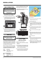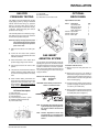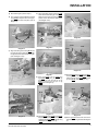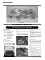
1
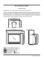
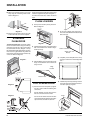
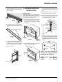
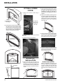
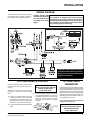
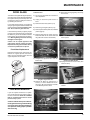
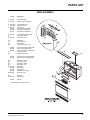
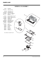
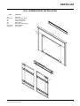
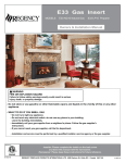
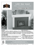
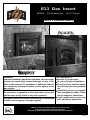
E33 Gas Insert
MODELS:
E33-NG Natural Gas
E33-LP Propane
Owners & Installation Manual
WARNING:
FOR YOUR SAFETY:
Improper installation, adjustment, alteration, service or main- What to do if you smell gas:
tenance can cause injury, property damage, or loss of life.
Do not try to light any appliance
Refer to this manual. For assistance or additional informaDo not touch any electrical switch:
tion consult an authorized installer, service agency or the
do not use any phone in your buildgas supplier.
ing.
FOR YOUR SAFETY:
Immediately call your gas supplier
Do not store or use gasoline or other flammable vapours and
from a neighbour's phone. Follow
liquids in the vicinity of this or any other appliance.
the gas supplier's instructions.
If you cannot reach your gas supInstallation and service must be performed by an authorized
plier, call the fire department.
installer, service agency or the gas supplier.
Tested by:
Installer: Please complete the details on the back cover
and leave this manual with the homeowner.
Homeowner: Please keep these instructions for future reference.
918-408
FPI FIREPLACE PRODUCTS INTERNATIONAL LTD. 6988 Venture St., Delta, BC, Canada V4G 1H4
08/16/05
FPI GAS FIREPLACE INSERT
TO THE NEW OWNER
Congratulations! You are the owner of a state-of-the-art Gas Insert by FPI.
The E33 Gas Insert has been designed to provide you with all the warmth and charm of a fireplace,
at the flick of a switch. The E33-NG and E33-LP have been approved by Warnock Hersey for
both safety and efficiency. As it also bears our own mark, it promises to provide you with economy,
comfort and security for many trouble free years to follow. Please take a moment now to acquaint
yourself with these instructions and the many features of your FPI Fireplace.
32-1/4"(819mm)
16-1/8"(410mm)
24-1/2"(622mm)
23-13/16"(605mm)
18"(203mm)
31-1/8"(790mm)
25"(635mm)
1-3/8"
(35mm)
11-1/4"
(286mm)
23"(583mm)
45-9/16"(1157mm)
16-1/2"(419mm)
2
E33 FPI Direct Vent Gas Insert
TABLE OF CONTENTS
FPI GAS FIREPLACE INSERT
Page
Page
OPERATING INSTRUCTIONS
Unit Dimensions ..................................................................... 2
Safety Label .......................................................................... 4
INSTALLATION REQUIREMENTS
For Your Safety ....................................................................... 5
Gas Pressure Testing ............................................................. 5
Specifications ......................................................................... 5
Installation into a Solid Fuel Burning
Fireplace or Factory Built Fireplace ................................ 5
General Safety Information .................................................... 5
Installation Checklist ............................................................... 6
Materials Required ................................................................ 6
Minimum Fireplace Dimensions ............................................. 6
Clearances to Combustibles .................................................. 7
Combustible Mantel Clearances ............................................ 7
INSTALLATION
Gas Connection ...................................................................... 8
Venting
.......................................................................... 8
Flue Liner Installation ............................................................. 8
Gas Pipe Pressure Test .......................................................... 9
SIT Valve Description ............................................................ 9
Gas Insert Aeration System .................................................... 9
Optional Brick Panel .............................................................. 9
Log Installation .................................................................... 10
E33 Conversion Kit from NG to LPG .................................... 12
Faceplate & Trim .................................................................. 13
Standard Flush Door ............................................................ 14
Flush Louvers ....................................................................... 14
Full Screen Front .................................................................. 14
Excalibur Surround Installation ............................................. 15
Optional Screen Doors ......................................................... 16
Accent Kit Installation ........................................................... 16
Double Door Option .............................................................. 16
Wiring Diagram ..................................................................... 17
Optional Remote Control ..................................................... 17
Optional Wall Thermostat ..................................................... 17
Final Check ........................................................................ 18
E33 FPI Direct Vent Gas Insert
First Fire
........................................................................ 18
Operating Instructions .......................................................... 18
Lighting Procedure ............................................................... 18
Shutdown Procedure ............................................................ 18
Copy of Lighting Instruction Plate ......................................... 19
Automatic Convection Fan Operation .................................. 19
Normal Operating Sounds of Gas Appliances ...................... 19
MAINTENANCE
Maintenance Instructions ..................................................... 20
General Vent Maintenance .................................................. 20
Log Replacement ................................................................. 20
Glass Gasket ....................................................................... 20
Steel or Gold Plated Trim ..................................................... 20
Door Glass ........................................................................ 21
Flush Glass Replacement .................................................... 21
Fan Maintenance .................................................................. 21
Valve Assembly Removal and Installation ........................... 22
REPLACEMENT PARTS LIST
Parts List
........................................................................ 23
WARRANTY
Warranty
........................................................................ 31
3
SAFETY LABEL
This is a copy of the labels that accompany each
E33 Gas Insert. We have printed a copy of the
contents here for your review. The safety label
is located on a plate inside the base of the unit
visible when the bottom louver is opened. Ensure
that the safety label is attached to the unit.
NOTE: FPI units are constantly being improved. Check the label on the unit and if
there is a difference, the label on the unit is
the correct one.
For the State of Massachusetts, installation
and repair must be done by a plumber or
gasfitter licensed in the Commonwealth of
Massachusetts.
For the State of Massachusetts, flexible
connectors shall not exceed 36 inches in
length.
For the State of Massachusetts, the appliances individual manual shut-off must be a
t-handle type valve.
4
E33 FPI Direct Vent Gas Insert
INSTALLATION
IMPORTANT:
SAVE THESE
INSTRUCTIONS
The FPI Gas Fireplace must be installed in
accordance with these instructions. Carefully
read all the instructions in this manual first.
Consult the building authority having jurisdiction to determine the need for a permit prior to
starting the installation.
NOTE: Failure to follow the instructions could
cause a malfunction of the heater which could
result in death, serious bodily injury, and/or
property damage. Failure to follow these
instructions may also void your fire insurance
and/or warranty.
FOR YOUR SAFETY
This appliance requires air for proper combustion. Always provide adequate combustion and
ventilation air. Follow instructions and information in CSA B149.1 (in Canada) or the National
Fuel Gas Code ANS Z223.1/NFPA (in the USA),
regarding requirements for combustion and
ventilation air.
GAS PRESSURE
TESTING
The appliance must be isolated from the gas
supply piping system by closing its individual
manual shut off valve during any pressure
testing of the gas supply piping system at test
pressures equal to or less than
1/2 psig. (3.45 kPa).
SPECIFICATIONS
At pressures over 1/2 psig, the pipe to the unit
must be disconnected.
Gas Input Capacity:
Natural Gas 38,000 Btu/h
Propane
35,500 Btu/h
Min. Input:
Natural Gas 20,000 Btu/h
Propane
19,000 Btu/h
Fuels: Approved for use with both natural gas,
and propane. Approved as is for use at 0' to
4,500' (0-1370m).
Electrical:
120V A.C. system.
Circulation Fan: Variable speed, 127 CFM.
Log Set:
Ceramic fibre, 8 per set.
Vent System:
3" co-linear aluminum flex.
E33 FPI Direct Vent Gas Insert
INSTALLATION INTO A
SOLID FUEL BURNING
FIREPLACE OR
FACTORY BUILT
FIREPLACE
The E33 Gas Inserts have been tested and approved to be vented into any masonry fireplace
or approved solid fuel burning factory built
fireplace that will allow the insert to physically
fit into the firebox. Refer to page 6 for minimum
fireplace clearances.
If the factory built fireplace* height is too low
for your Insert, you may remove the smoke
baffle plate and damper from the factory
built fireplace as long as these items are
saved and are reinstalled in the event that
the Insert is removed. NOTE: Any alterations
made to the listed solid fuel burning factory
built fireplace may void the listing of the
fireplace. Cutting any sheet-metal parts of
the fireplace, in which the gas fireplace insert
is to be installed, is prohibited.
If the factory-built fireplace has no gas access hole(s) provided, an access hole of
1.5" (37.5mm) or less may be drilled through
the lower sides or bottom of the firebox in
a proper workmanship like manner. This
access hole must be plugged with non-combustible insulation after the gas supply line
has been installed.
The fireplace and fireplace chimney must be
clean and in good working order and constructed of non-combustible materials and
chimney cleanouts must fit properly. Refractory, glass doors, screen rails, screen mesh,
and log grates can be removed from the
fireplace before installing the gas fireplace
insert. Smoke shelves, shields and baffles
may be removed if attached by mechanical fasteners. A tight connection between
the gas fireplace insert flue collar and the
fireplace chimney must be made.
*Check with your local inspector before commencing with this installation.
BEFORE YOU START
Safe installation and operation of this appliance
requires common sense, however, we are
required by the Canadian Safety Standards
and ANSI Standards to make you aware of
the following:
General Safety Information
1) The appliance installation must conform
with local codes or in the absence of local
codes, with CAN/CSA B149.1 (in Canada)
or the National Fuel Gas Code ANSI Z223.1
NFPA 54 in the U.S.A. This appliance should
be installed by a qualified gas fitter technician
only.
2) Installation and repair should be done
by a qualified service person.
3) The appliance should be inspected
before use and at least annually by a
professional service person. More frequent cleaning may be required due to
excessive lint from carpeting, bedding
material, animal hair, etc. It is imperative that control compartments, burners
and circulating air passageways of the
appliance be kept clean.
4) See general construction and assembly
instructions. This appliance may only be
installed in a vented, noncombustible fireplace.
5) This appliance is Listed for bedroom installations when used with a Listed Millivolt
Thermostat. Some areas may have further
requirements, check local codes before
installation.
6) Always connect this appliance to a vent
system vent that is run (or routed) to the
outside of the building envelope. Never vent
to another room or inside a building. Make
sure that the vent is properly sized and is
of adequate height to provide the proper
draft.
7) Inspect the venting system annually for
blockage and any signs of deterioration.
8) Any glass removed for servicing must be
replaced prior to operating the appliance.
9) WARNING: Failure to position the parts
in accordance with the diagrams in this
manual or failure to use only parts specifically approved with this appliance may
result in property damage or personal
injury.
10) To prevent injury, do not allow anyone who
is unfamiliar with the operation to use the
fireplace.
5
INSTALLATION
11) Due to high temperatures, the appliance
should be located out of high traffic areas
and away from furniture and draperies.
Children and adults should be alerted to
the hazards of high surface temperatures,
especially the fireplace glass, and should
stay away to avoid burns or clothing ignition.
Young children should be carefully supervised when they are in the same room as
the appliance. Clothing or other flammable
material should not be placed on or near
the appliance.
Emissions from burning wood or gas could
contain chemicals known to the State of California to cause cancer, birth defects or other
reproductive harm.
INSTALLATION
CHECKLIST
Before installing vent system ensure that the
damper plate is open and secure to prevent
the damper plate from falling down and crushing the liner.
The FPI Gas Insert is installed as listed
below.
1) Check all clearances to combustibles, see
page 7.
2) Make the gas connection. See page 8.
3) Install the 3" flue liner to the sliding connector
plate. See page 8.
4) Slide the unit half way into the fireplace.
14) Install optional Excalibur Surround. See
page 15.
15) Install optional remote control or wall thermostat, pages 17.
16) Final check (page 18): Before leaving this
unit with the customer, the installer must
ensure that the appliance is firing correctly.
This includes:
a)
Clocking the appliance to ensure the
correct firing rate.
b)
Adjusting the primary air, if required,
to ensure that the flame does not
carbon. See page 9.
c)
Ensuring that the appliance is venting
correctly.
7) Test gas pressure, page 9. Check aeration
system, page 9.
8) Install the optional brick panels. See page
9.
9) Install the log set. See page 10.
10) Assemble and install the faceplate and trim.
See page 13.
The minimum fireplace opening for the FPI
gas fireplace insert is shown in the following
diagrams:
MATERIALS
REQUIRED
No electrical power supply is required for the gas
control to operate. A 120 Volt AC power cord is
hooked up to the fan. Plug the 3 wire cord into
a suitable receptacle. Do not cut the ground
terminal off under any circumstances. When
connected with 120 volts, the appliance must
be electrically grounded in accordance with
local codes, current version of the Canadian
Electrical Code CSA C22.1 (in Canada) or in
the absence of local codes, with the National
Electrical Code ANSI/NFPA 70.
NOTE: This unit is equipped with a heat
sensor thermodisc which will prevent the
blower from operating until the unit reaches
the correct temperature.
5) Pull the vent connector plate through the
tapered brackets and fasten to the front
plate. See page 8.
6) Slide the unit fully into the fireplace.
MINIMUM FIREPLACE
OPENING
WARNING:
Electrical Grounding Instructions
This appliance is equipped with
a three pronged (grounding) plug
for your protection against shock
hazard and should be plugged
directly into a properly grounded
three-prong receptacle. Do not cut
or remove the grounding prong
from this plug.
MINIMUM FIREPLACE
OPENING EXCALIBUR
OPTION
The minimum fireplace opening for the FPI
gas fireplace insert is shown in the following
diagrams:
NOTE: If you are installing the Excalibur, the minimum fireplace dimensions
are as follows:
Width (at front):
Depth:
Height:
34-1/2" (876mm)
17-3/4" (451mm)
26"
(660mm)
11) Install the standard flush door. See
page 14.
12) Install both louvers. See page 14.
13) Install optional full screen doors. See page
16.
6
E33 FPI Direct Vent Gas Insert
INSTALLATION
MINIMUM CLEARANCES TO COMBUSTIBLES
From Unit
Side Walls
* A 8" (203 mm)
Ceiling
B 47" (1194 mm)
Min. Mantel Height
Max. Mantel Depth
C 15" (381 mm)
D 3-1/2" (89 mm)
Alcove Width
Alcove Depth
E
F
Hearth Height
Hearth Width
Hearth Depth
G 1-1/4" (32 mm)
H 45-1/2" (1156 mm)
I 13" (330 mm)
76" (1930 mm)
36" (914 mm)
* Alcove side wall must have a min. of 8"
clearance on one side.
REGENCY FLUSH
EXCALIBUR SURROUND & FULL SCREEN DOORS
COMBUSTIBLE MANTEL CLEARANCES
COMBUSTIBLE MANTEL CLEARANCES
Because of the extreme heat this fireplace emits, the mantel clearances are critical.
Combustible mantel clearances from top of unit are shown in the above diagrams.
Note: A non-combustible mantel may be installed at a lower height if the framing is made of metal studs covered with a non-combustible
board.
Mantel can be installed anywhere in shaded area or higher using the above scale.
Note: Ensure the paint that is used on the mantel and the facing is "heat resistant" or the paint may discolour.
E33 FPI Direct Vent Gas Insert
7
INSTALLATION
GAS CONNECTION
GAS CONNECTION WARNING:
Only persons licensed to work
with gas piping may make the
necessary gas connections to
this appliance.
In areas of consistently high winds, we recommend using the Simpson Dura-Vent System
(923GK adapter and 991 high-wind cap).
The Air Intake pipe must be attached to the inlet
air collar of the termination cap.
1) If the appliance is to be installed into an
existing chimney system, thoroughly clean
the masonry or factory built fireplace.
2) The appliance is provided with an opening
on the left hand side of the control compartment. A 3/8" NPT gas supply pipe must be
brought near this inlet hole.
5) Install flashing.
6) Insert both liners into chimney, passing
through the damper opening.
7) Install termination cap.
8) Connect the marked end of the liner to the
exhaust collar of the vent connector plate
marked with an "E", seal connection with
high temperature silicone. Secure with gear
clamp.
9) Connect the 2nd liner to the intake collar, seal
connection with high temperature silicone.
Secure with gear clamp.
3) Locate the center point where the vent will
pass through the chimney above the appliance. Move the appliance into the exact
location where it is to be installed. Ensure
that the Insert is level.
10) Align vent connector plate with guides on
unit.
11) Slide unit into masonry opening, while ensuring that the slot at the rear of the connector
plate mates up with the hold down plate on
the unit.
VENTING
THE APPLIANCE MUST NOT BE
CONNECTED TO A CHIMNEY FLUE
SERVING A SEPARATE SOLID FUEL
BURNING APPLIANCE.
This appliance is designed to be attached to
two 3" (76mm) co-linear aluminium flex running
the full length of the chimney. The flue length
must be a minimum length of 8 ' (2.44m) and
a maximum of 35' (10.7m). See chart above
for minimum distances from roof. Periodically
check that the vent is unrestricted.
Masonry chimneys may take various contours
which the flexible liner will accommodate.
However, keep the flexible liner as straight
as possible, avoid unnecessary bending.
Part #
948-305
946-529
Description
3" Flex - 35 ft.
FPI Co-linear DV Vertical
Termination Cap
12) Secure with Screw.
FLUE LINER
INSTALLATION
1) Cut the flex liner as required.
2) Mark the end of one liner to indicate
Exhaust.
NOTE:
1) Final gas connection should be made after
unit is in place to avoid damage to line when
pushing the unit into position.
2) Mill-pac may be used instead of high
tempture silicone and screws may be used
instead of gear clamps at connections of
liner to inlet and vent collars.
3) Connect the other end of the above liner to
the exhaust side of the termination adaptor, seal connection with high temperature
silicone. Secure with gear clamp.
4) Connect the 2nd liner to the inlet side of the
adaptor, seal connection with high temperature silicone. Secure with gear clamp.
Alternate Approved Caps
980
Vertical Termination Cap
991
High Wind Cap
923GK
3" Co-linear Adaptor with
flashing
8
E33 FPI Direct Vent Gas Insert
INSTALLATION
GAS PIPE
PRESSURE TESTING
OPTIONAL
BRICK PANEL
7) Pilot Outlet
8) Main Gas Outlet
9) Alternative TC Connection Point
Optional Brick Panel Set:
The appliance must be isolated from the gas
supply piping system by closing its individual
manual shut-off valve during any pressure
testing of the gas supply piping system at
test pressures equal to or less than 1/2 psig.
(3.45 kPa). Disconnect piping from valve at
pressures over 1/2 psig.
Part #
Description
Top (brick) panel
Back (brick) panel
Left (brick) panel
Right (brick)panel
340-043 Top bracket
340-094 Bottom clips
511-031 Brick clips
The manifold pressure is controlled by a regulator built into the gas control, and should be
checked at the pressure test point.
Qty
1
1
1
1
1
2
2
NOTE: To properly check gas pressure, both
inlet and manifold pressures should
be checked using the valve pressure
ports on the valve.
1) Make sure the valve is in the "OFF" position.
2) Loosen the "IN" and/or "OUT" pressure
tap(s), turning counterclockwise with a 1/8"
wide flat screwdriver.
3) Attach manometer to "IN" and/or "OUT"
pressure tap(s) using a 5/16" ID hose.
4) Light the pilot and turn the valve to "ON"
position.
5) The pressure check should be carried out
with the unit burning and the setting should
be within the limits specified on the safety
label.
6) When finished reading manometer, turn
off the gas valve, disconnect the hose and
tighten the screw (clockwise) with a 1/8"
flat screwdriver. Note: Screw should be
snug, but do not over tighten.
GAS INSERT
AERATION SYSTEM
The air shutter can be adjusted by moving the
adjusting wire up or down. The wire is accessed
through the bottom louver opening. Open the air
shutter for a blue flame or close for a yellower
flame. The burner aeration is factory set but
may need adjusting due to either the local gas
supply or altitude.
Minimum Air Shutter Opening:
5/16"
Natural Gas
7/16"
Propane
CAUTION: Carbon will be produced if air
shutter is closed too much.
Gas cock knob
Manual high/low adjustment
Pilot Adjustment
Thermocouple Connection - option
Manifold (Outlet) Pressure Tap
Inlet Pressure Tap
2
1
IN
6
3
OUT
4
2) Remove the logs if they are already in
stalled. Note: the grate must be removed in
order to remove the bottom log. Ensure you
slide the bottom coal off to the right-hand
side to avoid chipping.
3) Unwrap the brick pattern panels from the
protective wrapping. Handle the panels with
care as they can break easily.
4) Remove the two screws from the bottom of
the baffle plate. Install the bottom clips onto
the baffle plate (refer to Diagram 1).
SIT Valve Description
1)
2)
3)
4)
5)
6)
Installation of Brick Panels:
1) Remove top louver and glass door if installed.
Note: Any damage due to carboning resulting from improperly setting the aeration controls is NOT covered under
warranty.
Note: Aeration Adjustment should only
be performed by an authorized FPI
Installer at the time of installation or
service.
Bottom Clips
Diagram 1
5
E33 FPI Direct Vent Gas Insert
9
INSTALLATION
5) Place the top bracket onto the top edge of
the top panel (refer to Diagram 2).
10) Install the 2 brick retaining clips, one on
each side.
03-23
Top Bracket
03-22
03-24
03-18
03-20
03-19
03-21
03-17
Diagram 2
The "03" reference numbers (i.e. 03-23)
are molded into the rear of each log.
6) Slide the top panel and bracket assembly
carefully onto the baffle plate ensuring the
panel is centered. Make sure the tabs of the
top bracket fit into the baffle openings (refer to
Diagram 3).
Instructions:
1) Remove and carefully unwrap the logs from
the box. Please handle with care and do not
force them into position to avoid chipping.
2) Remove the top louver and flush door if
installed (refer to page 14).
Final Installation
3) To remove the grate, loosen the two
Phillips screws which are securing
the grate. Slide the grate outwards
to remove it from the unit (refer to
Diagram 1).
Screws
Diagram 3
7) Insert the back panel by sliding it between
the sidewalls of the firebox and the rear log
support.
8) Before installing the side brick panels, remove the screws from the side brick clips
(refer to Diagram 4).
LOG INSTALLATION
WARNING: Dangerous operating conditions may occur if these logs are not
positioned in their correct certified
locations. Read the following instructions carefully and refer to the attached
diagram.
Materials Required:
Diagram 4
9) Insert the side panel by positioning it flat
against the side walls. Tilt the panel
towards the middle of the firebox, then insert
the bottom front corner. Repeat on the other
side.
Complete Log Set (Part # 340-930)
Contains the following:
Description
03-17
Bottom Log
03-18
Center Top Log
03-19
Front Log
03-20
Left Log
03-21
Right Log
03-22
Left top Log
03-23
Rear Log
03-24
Right Top Log
Diagram 1
4) Angle log 03-17 and slide it between the
top and bottom burner tube under the “T”
section until it touches the left grate support
bracket (refer to Diagram 2).
03-17
Diagram 2
10
E33 FPI Direct Vent Gas Insert
INSTALLATION
5) Re-install the grate (reverse step 3).
6) Line up the pin holes (located at the bottom
of log 03-23) to the pins of the rear log support and position them into place. (refer to
Diagram 3)
8) Align and position the pin hole of log 03-20
down into the left locating pin of log 03-21.
Slide into the groove and gently place into
position until it touches the locating tab.
(see Diagram 6 & 7)
03-23
03-18
Tab
Locating
Pins
03-20
03-20
03-23
Locating
Pin
Locating
Tab
Diagram 9
03-21
Locating Pins
03-23
Diagram 6
Diagram 3
7) Align the bottom grooves of log 03-21 onto
the right side of the grate and gently slide
the log back until it touches the locating tab
(refer to Diagram 4 & 5).
03-18
03-22
03-23
03-21
03-20
03-17
03-21
03-17
Diagram 10
Locating
Tab
Diagram 7
9) Place log 03-22 over log 03-23 and
log 03-20. Ensure the pin hole of log
03-22 lines up with the left pin of log
03-23 as well as the left pin of log
03-20 (refer to Diagram 8).
11) Place log 03-24 over log 03-23 and log 03-21
ensuring the pin hole of log 03-24 lines up
with the right pin of log 03-23 and the right
pin of log 03-21 (refer to Diagram 11).
Diagram 4
03-24
03-23
03-23
03-22
03-23
03-20
Locating
Pins
Locating
Pins
03-21
03-21
03-17
Diagram 8
Diagram 5
E33 FPI Direct Vent Gas Insert
10) Place log 03-18 over log 03-23 and log 03-20.
Ensure the pin hole of log 03-18 lines up with the
middle pin of log 03-23 and the right pin of log
03-20 (refer to Diagram 9 & 10).
Diagram 11
12) Place log 03-19 over the left center of the
grate. Ensure the log set looks like Diagram
12.
11
INSTALLATION
03-19
Final Installation
E33 CONVERSION KIT FROM NG TO LPG
THIS CONVERSION MUST BE DONE BY A QUALIFIED GAS FITTER
IF IN DOUBT DO NOT DO THIS CONVERSION !!
Conversion Kit Contains:
Qty. Part #
1 910-018
1
1
910-037
904-641
1
1
1
1
1
908-255
904-529
918-415
Description
SIT Conversion Kit-50%
Turndown LPG
LPG (Pilot Orifice)
Burner Orifice #50
(rated at 35,500 BTU/HR)
Label "Converted to LPG"
5/32" Allen Key
Instruction Sheet
Red LPG Label
Silver "Converted to
LPG" Label
5) Remove burner by unscrewing the 2
screws.
9) Reinstall new burner orifice LPG stamped
#50 and tighten.
6) Pull off the pilot cap to expose the pilot
orifice.
10) Remove and discard the 3 pressure regulator mounting screws (A),
pressure regulator (B) and diaphragm (C)
refer to Diagram 1.
7) Unscrew the pilot orifice with the allen
key and replace with the LPG pilot orifice
provided in the kit, then replace pilot cap.
12) Reverse steps 5) to 3).
Instructions:
1) Shut off the gas supply.
13) Attach clear label "This unit has been
converted to LPG" near or on the serial #
decal. Attach silver label "This valve has
been converted from NG to LPG using SIT
conversion Kit Code 0.907.202" onto the
valve.
2) Remove the louvers and flush door.
3) Remove the logs and grate (refer to p.10).
Ensure you slide the bottom log 03-17 off
to the right-hand side to avoid chipping.
4) Remove front base brick.
11) Ensure that the rubber gasket (D) is properly
positioned. Install the new HI/LO pressure
regulator assembly to the valve using the
new screws (E) supplied with the kit. Tighten
screws securely.
8) Remove the burner orifice by using a 1/2"
wrench, while using a 9/16" wrench to hold
onto the elbow behind the orifice.
14) Replace yellow "NG" label with red "LPG"
label.
15) Check for gas leaks with a proper soapy
solution or leak detector.
16) Check for proper spark between the ignitor
and pilot cap. Refer to “Lighting Procedure”
(page 18) for lighting sequence.
17) Check pilot flames. Correct flame pattern
has 3 strong blue flames. Adjustment can
be made by turning the slotted screw at
the top right corner of the valve. Refer to
Burner Orifice Removal
12
E33 FPI Direct Vent Gas Insert
INSTALLATION
“Maintenance Instructions” (page 20) for
correct flame patterns.
18) Check inlet (12” WC min) and outlet (11”
WC) pressures. Refer “Gas Pipe Pressure
Testing” (page 9).
19) Check operation of flame control.
20) Check for proper flame appearance and
glow on logs.
FACEPLATE & TRIM
INSTALLATION
1) Lay the faceplate panels flat, face down on
something soft so they don't scratch.
2) Take the top faceplate and align the holes
in it with the holes in the side panels. Using the screws provided, attach from the
top of the panel (the holes in the top panel
are slightly larger than the holes in the side
panel to facilitate easier installation). Refer
to Diagram 1.
Hint: Don't tighten the screws down completely at this point, continue on with steps
3 and 4 and do a trial fit to the unit. Make
any necessary adjustments and when it fits
properly then tighten down the screws.
4) Place the trim on the assembled faceplate
panels, aligning the wire connections from
the switches with the notch on the left side
panel.
5) Connect the fan switch wires by taking the
black and red wires with the male ends (in
the grey harness) and connect them with
the wire connectors from the fan speed
control.
6) Connect the ON/OFF switch wires by taking
the black and red wires with the female ends
and connect them to the ON/OFF switch.
7) Tuck the wires into the faceplate to keep
them away from the insert using the clip
provided. Attach the clip to the rear of the
faceplate to ensure that the wires do not
touch the side of the unit. Refer to Diagram
3.
8) The power cord should be run behind the
faceplate panel.
Pilot
Adjustment
Screw
Diagram 1
Diagram 3
WARNING:
This conversion kit shall be installed by a
qualified service agency in accordance with
the authority having jurisdiction. If the information in these instruction is not followed
exactly, a fire, explosion or production of
carbon monoxide may result causing property damage, personal injury or loss of life.
The qualified service agency is responsible
for the proper installation of this kit. The
installation is not proper and complete until
the operation of the converted appliance is
checked as specified in the manufacturer’s
instructions supplied with the kit.
Rear View: Faceplate Assembly
Diagram 1
9) Attach the trim to the faceplate by using the
plated screws (refer to Diagram 4).
3) Using the connectors provided, join the left
side trim (with the ON/OFF switch) to the
top trim. Diagram 2. Connect the right side
trim to the top trim.
Note: Equipped for Altitude 0-4500 ft.
(0-1370m).
Installer Notice:
These instructions must be
left with the appliance.
Rear View: Trim Assembly
Diagram 2
E33 FPI Direct Vent Gas Insert
Diagram 4
13
INSTALLATION
10) Attach the faceplate panels to the insert
body using the 4 remaining black screws.
Refer to Diagram 5.
Secure door by fastening with two screws located
at bottom of glass frame (refer to Diagram 1).
To remove the flush door, reverse the above
steps.
FLUSH LOUVERS
1) The top louver is held in place by friction fit.
Refer to Diagram 1
2) Lift the unit up slightly and push down on
the corners of the Bottom Trim Bracket and
slide under unit.
Diagram 5
11) Push the FPI logo plate into the two holes
in the bottom left corner of the faceplate.
STANDARD
FLUSH DOOR
Diagram 1
The standard flush door comes with a black
frame. To install the frame, simply hook the top
door flange onto the top of the unit and swing
the door towards the unit, (Diagram 1 and 2).
Be careful that the glass gasket does not roll up;
there must be a gap between the gasket and
the door lip to ensure that the door sits securely
on the unit. Refer to Diagram 3.
2) Install the Spring Hinges on the left and right
side of the bottom of the Firebox using 2
screws per hinge.
Push in Corners
Bottom Trim
Bracket
Diagram 1
3) Place the Bottom Louver near the hinge. Flip
hinge over the Bottom Louver and secure
using 3 screws.
3) Completely secure faceplate to the unit by
securing 4 screws to the Left and Right Side
Trim.
Hinge
Location
Screws
Bottom Louver
Diagram 2
FULL SCREEN FRONT
4) Install the Top Frame by hooking it onto the
two screws at the top of the full screen door.
It is held in place by magnets.
1) Hold the full screen faceplate up against
the unit in order to make the following wire
connections.
Pull the ON/OFF connector wires thru the
box and connect them to the switch.
Diagram 3
Screw
Connect the fan switch wires with the wire
connectors from the fan speed control. Place
clips over wires and tuck into side trim.
Top Frame
14
E33 FPI Direct Vent Gas Insert
INSTALLATION
5) Install Spring Hinges to the Left and Right
Side of the bottom of the firebox using 2
screws per hinge.
EXCALIBUR SURROUND
INSTALLATION
IMPORTANT NOTE:
When using the Surround, the unit must be set 1"
further into the fireplace than the standard faceplate installation. See page 6 for the Minimum
Fireplace Opening Excalibur Option.
3) Hold the Faceplate Trim up against the unit
in order to make the following wire connections.
3a) Pull the ON/OFF connector wires from the
firebox and connect them to the switch.
3b) Connect the fan switch wires with the wire
connectors from the fan speed control. Place
clips over wires and tuck into side trim.
1) Align the left side Faceplate Trim Bracket
with the Firebox Flange and secure using
2 screws as shown in diagram 1. Repeat
for right side.
ON/OFF
switch
wires to
ON/OFF
switch
6) Place Bottom Frame near hinge. Flip hinge
over Bottom Frame and secure with 3 screws
each.
for gas
connection
Hinge Location
Firebox
Faceplate Flange
Trim Bracket
Bottom
Frame
Diagram 1
7) Install the Left and Right Side Screen Doors
by placing over top of the hinges on the
faceplate. Hold the door at a 45 degree
angle to avoid scratching the faceplate.
8) Close screen doors.
Faceplate
Trim Bracket
2) Push the Blanking Plate down on top of the
Glass Door (refer to Diagram 2).
Blanking Plate
Fan Speed
Switch
(Rear View)
wires to
Fan switch
connectors
Self-adhesive
wire clip
4) Secure the Faceplate by sliding the slots in
the Faceplate into the flanges on the left and
right side Faceplate Trim Brackets. Once the
Faceplate is in place secure using 2 screws
per side.
Faceplate
Slots
NOTE: If you are installing the
Excalibur, the minimum fireplace
dimensions are as follows:
Top of
Glass
Door
Hinge
Width (at front): 34-1/2" (876mm)
Depth:
17-3/4" (451mm)
Height:
26"
(660mm)
Diagram 2
Screen Door
E33 FPI Direct Vent Gas Insert
15
INSTALLATION
OPTIONAL SCREEN
DOORS
1) Attach door bracket to sides using 4
screws.
2) Take the hoseclamps and put them over the
back of each rivet. Squeeze the hoseclamp
to secure onto rivets ensuring that the
hoseclamp is touching the back side of
the surround. The hoseclamp can now be
released.
3) Remove the handles by removing the nut
and screw. Install the new handles by placing them in position over the holes on the
surround louver. Put the screws through
the holes and secure them by tightening
them with a nut.
Left Side
Faceplate Bracket
Trim Flange
Door Bracket
attaches with
2 screws on
each side.
5) Place the bottom hooks of the Surround into
the bottom slots of the Faceplate. Slightly
pull up the Surround and push the top hooks
into the top slots of the Faceplate. Push
down to secure. Tug on the Surround to
ensure it is securely locked in place.
Double Screen Door: attach to left and right
side of unit.
Backside of
Surround Shown
4) Place the emblem over the emblem design
on the surround. Insert the studs through the
holes. To secure them first put on the split
lock washer and then the nut and tighten.
2) Slide the door(s) onto the hinges.
Hooks
5) Remove the 2 studs on the sides of the Hood.
Insert the new studs through the holes and
secure them by first putting on the washer
and then tighten with a nut.
Faceplate Slots
ACCENT KIT
INSTALLATION
Faceplate
Surround
16
1) Remove the rivets from the surround by
pulling off the hoseclamp (located at the
backside of surround) with a screwdriver or
plyer. Re-install the rivets by putting them
through the holes on the sides of the surround.
DOUBLE DOOR OPTION
Remove the handles by removing the nut
and screw. Install the new handles by placing them in position over the holes on the
door(s). Put the studs through the holes
and secure them by tightening them with a
nut.
E33 FPI Direct Vent Gas Insert
INSTALLATION
WIRING DIAGRAM
This heater does not require a 120V A.C. supply
for operation. However, a 120V A.C. power supply is needed for the fan/blower operation.
Caution: Ensure that
the wires do not touch
any hot surfaces and
are away from sharp
edges.
WARNING: Electrical Grounding Instructions
This appliance is equipped with a three pronged
(grounding) plug for your protection against shock
hazard and should be plugged directly into a properly
grounded three-prong receptacle. Do not cut or remove
the grounding prong from this plug.
CAUTION: Label all wires prior to disconnection when servicing controls.
Wiring errors can cause improper and
dangerous operation.
OPTIONAL REMOTE CONTROL
ON
HI
THTP TP TH
2) Connect the wires as per the wiring diagrams
below.
PILO
T
1) Choose a convenient location on the wall
to install the receiver and the receptacle
box (protection from extreme heat is very
important). Run wires from the fireplace to
that location. Use Thermostat Wire Table.
3) Install 3 AAA alkaline batteries in transmitter
and 4 AA alkaline batteries in the receiver.
Install the receiver and its cover in the wall.
Switch the remote receiver to "remote"
mode. The remote control is now ready for
operation.
OFF
The remote control kit comes with a hand held
transmitter, a receiver and a wall mounting
plate.
CAUTION
Do not connect the millivolt
remote control wires
to the 120V wires.
LO
Use the FPI Remote Control Kit approved for
this unit. Use of other systems may void your
warranty.
To thermopile
E33 FPI Direct Vent Gas Insert
To wall switch,
remote control
or thermostat
OPTIONAL WALL
THERMOSTAT
A wall thermostat may be installed if desired,
follow the wiring diagram below. Note: the wires
are connected to the "TH" on the gas valve. Use
the table below to determine the maximum wire
length. FPI offers an optional programmable
thermostat but any 250-750 millivolt rated nonanticipator type thermostat that is CSA, ULC
or UL approved may be used.
It is recommended that the thermostat be
installed on an interior wall.
CAUTION
Do not connect the millivolt
wall thermostat wires
to the 120V wires.
17
OPERATING INSTRUCTIONS
Thermostat Wire Table
Recommended Maximum Lead Length
(Two-Wire) When Using Wall
Thermostat (CP-2 System)
Wire Size
Max. Length
14 GA.
16 GA.
18 GA.
20 GA.
22 GA.
50 Ft.
32 Ft.
20 Ft.
12 Ft.
9 Ft.
FINAL CHECK
DO NOT BURN THE APPLIANCE
WITHOUT THE GLASS FRONT IN
PLACE.
During the first few fires, a white film
may develop on the glass front as part
of the curing process. The glass should
be cleaned or the film will bake on and
become very difficult to remove. Use a
non-abrasive cleaner and NEVER clean
the glass while it is hot.
OPERATING
INSTRUCTIONS
2) Turn gas control knob so indicator points
to "OFF" position and allow 5 minutes for
any gas in the combustion chamber to
escape.
3) Turn gas control knob counterclockwise
so indicator points to the "PILOT" position.
Depress the gas control knob fully. Depress
the ignitor button several times until the
pilot lights. After approximately one minute,
release the gas control knob. The pilot flame
should continue to burn. If the pilot does not
remain lit, repeat operation allowing a longer
period before releasing gas control knob.
4) When the pilot stays lit, turn the gas knob
further counterclockwise to the "ON" position.
5) Reinstall the glass door (refer to page 14).
Before leaving this unit with the customer, the
installer must ensure that the appliance is firing
correctly. This includes:
1) Read and understand these instructions
before operating this appliance.
2) Check to see that all wiring is correct and
enclosed to prevent possible shock.
1) Clocking the appliance to ensure the correct firing rate (rate noted on label) at 15
minutes.
3) Check to ensure there are no gas leaks.
2) If required, adjusting the primary air to ensure
that the flame does not carbon. First allow
the unit to burn for 15 min. to stabilize.
4) Make sure the glass in the door frame is
properly positioned. Never operate the appliance with the glass removed.
3) Check for proper draft.
5) Verify that the venting and cap are unobstructed.
CAUTION
Any alteration to the product that
causes sooting or carboning that
results in damage to the exterior
facia is not the responsibility of
the manufacturer.
FIRST FIRE
The first fire in your stove is part of the paint
curing process. To ensure that the paint is
properly cured, it is recommended that you
burn your fireplace for at least four (4) hours
the first time you use it with the fan on. When
first operated, the unit will release an odour
caused by the curing of the paint, the burning
off of any oils remaining from manufacturing.
Smoke detectors in the house may go off at
this time. Open a few windows to ventilate the
room for a couple of hours.
6) Ensure that the brick panels, if used, are
installed.
7) Verify log placement. If the pilot cannot be
seen when lighting the unit, the logs have
been incorrectly positioned.
SHUTDOWN
PROCEDURE
1) Use the switch, thermostat or remote control
to turn off the main burner.
2) Turn the main gas control clockwise to the
"OFF" position to turn off the pilot.
3) Turn off all electric power to appliance if
service is to be performed.
LIGHTING
PROCEDURE
IMPORTANT
Prior to igniting or reigniting the
pilot, remove the glass door.
The glass panel may require cleaning after the
unit has cooled down.
DO NOT ATTEMPT TO CLEAN THE
GLASS WHILE IT IS HOT.
IMPORTANT: Gas cock knob cannot be
turned from "PILOT" to "OFF" unless it is
partially depressed.
18
7) Rotate the flame height regulator to adjust
the flame height higher or lower.
8) The unit should never be turned off, and on
again without a minimum of a 60 second
wait.
Only when the pilot holds, without pressure
being applied to the control knob, should you
reinstall the glass door. The unit must not be
operated with the glass door removed.
Note: When the glass is cold and the appliance is lit, it may cause condensation
and fog the glass. This condensation
is normal and will disappear in a few
minutes as the glass heats up.
6) Use the switch, thermostat or remote control
to turn on the unit.
1) Turn burner OFF using "ON/OFF" switch.
E33 FPI Direct Vent Gas Insert
OPERATING INSTRUCTIONS
COPY OF LIGHTING INSTRUCTION PLATE
AUTOMATIC
CONVECTION
FAN OPERATION
The fan operates automatically. Turn the knob on
the side of the faceplate to adjust to the desired
speed. The fan will turn on as the stove comes
up to operating temperature. After the unit has
been turned off and the unit has been cooled
to below useful heat output range, the fan will
shut off automatically.
NORMAL OPERATING
SOUNDS OF
GAS APPLIANCES
It is possible that you will hear some sounds
from your gas appliance. This is perfectly normal
due to the fact that there are various gauges
and types of steel used within your appliance.
Listed below are some examples. All are normal
operating sounds and should not be considered
as defects in your appliance.
Blower:
FPI gas appliances use high tech blowers to
push heated air farther into the room. It is not
unusual for the fan to make a "whirring" sound
when ON. This sound will increase or decrease
in volume depending on the speed setting of
your fan speed control.
Burner Tray:
The burner tray is positioned directly under the
burner tube(s) and logs and is made of a different gauge material from the rest of the firebox
and body. Therefore, the varying thicknesses of
steel will expand and contract at slightly different
rates which can cause "ticking" and "cracking"
sounds. You should also be aware that as there
are temperature changes within the unit. These
sounds will likely re-occur. Again, this is normal
for steel fireboxes.
Blower Thermodisc:
When thermally activated switch turns ON, it
will create a small "clicking" sound. This is the
contact switch closing.
Pilot Flame:
While the pilot flame is on it will make a slight
"whisper" sound.
Gas Control Valve:
As the gas control valve turns ON and OFF, a
dull clicking sound may be heard. This is normal
operation of a gas regulator or valve.
Unit Body and Firebox:
Different types and thicknesses of steel will expand and contract at different rates resulting in
some "cracking" and "ticking" sounds which will
be heard throughout the cycling process.
E33 FPI Direct Vent Gas Insert
19
MAINTENANCE
MAINTENANCE
INSTRUCTIONS
1) Always turn the gas valve to the off position before cleaning. For relighting, refer to
lighting instructions. Keep the burner and
control compartment clean by brushing and
vacuuming at least once a year.
When cleaning the logs, use a clean soft
paint brush as the logs are fragile and easily
damaged.
2) Clean (never when unit is hot) appliance,
door and louvers with a damp cloth. Never
use an abrasive cleaner. The optional finishes on louvers and doors may be scratched
if abrasives are used to clean them. The
heater is finished in a heat resistant paint
and should only be refinished with heat
resistant paint (not with wall paint). FPI uses
StoveBrite Paint - Metallic Black #6309.
3) Make a periodic check of the burner for
proper position and condition. Visually
check the flame of the burner periodically,
making sure the flames are steady: not
lifting or floating. If there is a problem, call
a qualified service person.
4) The appliance and venting system must be
inspected before use, and at least annually,
by a qualified field service person, to ensure
that the flow of combustion and ventilation
air is not obstructed.
During the annual service call, the burners
should be removed and cleaned from the
burner tray.
CLOTHING OR OTHER FLAMMABLE MATERIAL SHOULD NOT
BE PLACED ON OR NEAR THE
APPLIANCE.
6) Each time the appliance is lit, it may cause
condensation and fog the glass. This
condensation and fog is normal and will
disappear in a few minutes as the glass
heats up.
Never operate the appliance without the
glass properly secured in place or with
the door open.
7) Do not use this appliance if any part has been
under water. Immediately call a qualified
service technician to inspect the appliance
and to replace nay part of the control system
and any gas control which has been under
water.
8) Periodically check the pilot flames. Correct
flame pattern has three strong blue flames: 1
flowing around the thermopile and 1 around
the thermocouple, and 1 flowing across the
front of the burner.
Note: If you have an incorrect flame pattern,
contact your FPI dealer for further
instructions.
Front Burner Tube
Top view of pilot flame
CAUTION: ANY SAFETY SCREEN
OR GUARD REMOVED FOR
SERVICING AN APPLIANCE
MUST BE REPLACED PRIOR TO
OPERATING THE APPLIANCE.
20
Conduct an inspection of the venting system
semi-annually. Recommended areas to inspect
as follows:
1) Check the Venting System for corrosion in
areas that are exposed to the elements.
These will appear as rust spots or streaks,
and in extreme cases, holes. These components should be replaced immediately.
2) Remove the Termination Cap, and shine a
flashlight down the Vent. Remove any bird
nests, or other foreign material.
3) Check for evidences of excessive condensation, such as water droplets forming in the
inner liner, and subsequently dripping out the
joints. Continuous condensation can cause
corrosion of caps, pipe, and fittings. It may
be caused by having excessive lateral runs,
too many elbows, and exterior portions of the
system being exposed to cold weather.
4) Inspect joints to verify that no pipe sections
or fittings have been disturbed, and consequently loosened. Also check mechanical
supports such as Wall Straps, or plumbers'
tape for rigidity.
LOG REPLACEMENT
5) Keep the area near the appliance clear and
free from combustible materials, gasoline
and other flammable vapours and liquids.
WARNING: CHILDREN AND
ADULTS SHOULD BE ALERTED
TO THE HAZARDS OF HIGH
SURFACE TEMPERATURE AND
SHOULD STAY AWAY TO AVOID
BURNS OR CLOTHING IGNITION.
YOUNG CHILDREN SHOULD
BE CAREFULLY SUPERVISED
WHEN THEY ARE IN THE SAME
ROOM AS THE APPLIANCE.
GENERAL VENT
MAINTENANCE
Incorrect flame pattern will have small, probably
yellow flames, not coming into proper contact
with the rear of the burner or thermopile.
The unit should never be used with broken logs.
Turn off the gas valve and allow the unit to cool
before opening door to carefully remove the
logs. The pilot light generates enough heat to
burn someone. If for any reason a log should
need replacement, you must use the proper
replacement log. The position of these logs
must be as shown in the diagram under Log
Installation.
NOTE: Improper positioning of logs may create
carbon build-up and will alter the unit’s performance which is not covered under warranty.
GLASS GASKET
If the glass gasket requires replacement use
a tadpole gasket for the Flush Front (Part #
936-155).
STEEL OR GOLD TRIM
The steel or 24 carat gold plated finish on the
louvers requires little maintenance, and need
only be cleaned with a damp cloth. DO NOT use
abrasive materials or chemical cleaners, as they
may harm the finish and void the warranty.
Front Burner Tube
Top View of pilot flame
Clean any fingerprints off before turning the
unit on. If the top louvers start to discolour,
check the door gasket seal and replace if
necessary.
E33 FPI Direct Vent Gas Insert
MAINTENANCE
DOOR GLASS
Your FPI stove is supplied with high temperature,
5 mm Neoceram ceramic glass that will withstand
the highest heat that your unit will produce. Do
not abuse the glass by striking the surface or
by slamming the door shut.
If your glass requires cleaning, we recommend
using an approved glass cleaner available at all
authorized dealers. Do not use abrasive materials. Do not clean the glass when hot.
In the event that you break your glass by impact,
purchase your replacement from an authorized
FPI dealer only, do not use substitute materials.
Follow our step-by-step instructions for replacement. Warning: Wear gloves when removing
damaged or broken glass.
Caution: Do not operate appliance with
glass panels removed, cracked or broken.
Replacement of the glass should be done by
a licensed or qualified service person.
9) Remove the rear log support by unscrewing
the 2 screws.
To Remove Fan:
1) Turn the unit off and allow it to cool down to
room temperature.
2) Unplug or disconnect power source to
stove.
Screws
3) Remove the flush door (refer to p.14).
4) Remove logs and grate (refer to p.10).
5) Remove optional brick panel set, if installed
(refer to page 9).
6) Remove base brick set. (When removing
base brick sides the two screws that hold
the grate down must be removed first).
10) Remove the 12 screws holding the Access
Panel in place.
Screws
Flush Glass Replacement
Remove the flush door front (refer to page 14).
Remove the 4 glass clips from each corner.
Slide in the new replacement glass. Push the
4 glass clips back onto the frame.
7) Straighten the adjustment wire under the
firebox base.
Fan Access Plate Screws
11) Unplug the wires from the fan motor (from
inside the stove).
Air Shutter Wire
Straighten adjustment wire.
8) Remove the Burner by removing the 2
screws (1 on burner bracket and one on
valve tray). Tilt up the left burner and slide
to the left away from the orifice.
12) Remove the 2 screws from the fan
bracket.
FAN MAINTENANCE
If your fan requires maintenance or replacement, access to the fan is through the plate on
the floor of the firebox. NOTE: the unit MUST
NOT be operated without the fan access
panel securely in place.
Screws
Screws
Caution: Label all wires prior to disconnecting when servicing controls. Wiring
errors can cause improper and dangerous operation. Verify proper operation
after servicing.
E33 FPI Direct Vent Gas Insert
21
MAINTENANCE
13) Pull Fan Assembly forward, to disengage
the fan clip on the rear wall. Then lift the
Fan Assembly up and pull through firebox
opening.
7) Remove base brick set. (When removing
base brick sides the two screws that hold
the grate down must be removed first).
11) Disconnect the inlet gas line.
12) Unplug the black and red wires at the valve.
Undo the 2 TP wires at the valve.
13) Remove the 17 screws on the valve tray.
Screws
8) Straighten the adjustment wire under the
firebox base.
14) Take out the valve tray from the unit.
Air Shutter Wire
14) Disconnect green wire from power cord.
Straighten adjustment wire.
9) Remove the Burner by removing the 2
screws (1 on burner bracket and one on
valve tray). Tilt up the left burner and slide
to the left away from the orifice.
16) Install new gasket and valve assembly
(reverse steps 9-14).
Replacing fan:
15) Reverse above steps.
Seal fan access panel using high temperature
silicone (sparingly).
Screws
18) Set up the air shutter to 5/16" for NG and
7/16" for LP.
10) Remove the rear log support by unscrewing
the 2 screws.
Screws
2) Unplug or disconnect power source.
NOTE: Failure to install a new gasket may
severely affect the appliance performance.
17) Hook up gas line and check for gas leaks
with soap and water solution or a gas leak
detector. Do not use open flame for leak
testing.
VALVE ASSEMBLY
REMOVAL AND
INSTALLATION
1) Turn the unit off and allow it to cool down
to room temperature.
15) Scrape off the old gasket from the floor of the
firebox and from the valve access plate.
19) Fire up the unit temporarily.
20) Check the manifold pressure 3.8" W.C. for
NG and 11" W.C. for LP.
21) Reverse steps 4-8.
3) Shut off the main gas supply.
4) Remove the louvers and glass door (refer
to page 14).
5) Remove logs and grate (refer to page 10).
6) Remove optional brick set, if installed (refer
to page 9).
22
E33 FPI Direct Vent Gas Insert
PARTS LIST
MAIN ASSEMBLY
Part #
Description
1) 340-038
2) 340-103
Fan Access Plate
Gasket - Fan Access Plate
3) 320-517/P
910-331/P
5) 910-750
910-752
910-692
910-737
Fan Assembly 120 V
Fan Motor 120 V
Power Cord
Wire Harness (Faceplate)
Wire Fan to Power Cord
Wire Valve to Spill Switch
7) 910-142
8) *
9) 320-070
Fan Auto On/Off Thermodisc
Thermodisc Bracket
Fan Switch Cover
13) *
17) *
18) *
19) *
Baffle Plate
Wire Holder Clip
Strain Relief
Grommet for Power Cord
340-924
340-922
340-926
21) *
23) *
Flush Louvers (Set) - Black/Gold
Flush Louvers (Set) - Black
Flush Louvers (Set) - Black/Steel
Top Flush Louver
Bottom Flush Louver
340-901
340-902
Brick Panel Set - Standard Brown
Brick Panel Set - Standard Red
33) *
34) *
35) *
36) *
37) 511-031
340-094
340-043
340-528
38) 340-043
Brick Panel - Right
Brick Panel - Left
Brick Panel - Back
Brick Panel - Top
Brick Clips
Bottom Clips
Top Bracket
Base Brick Panel (3pc)
Brick Front Trim
43) *
44) 340-099
Stove Top
Gasket Vent
918-408
Manual
* Not available as a replacement part.
E33 FPI Direct Vent Gas Insert
23
PARTS LIST
BURNER & LOG ASSEMBLY
Part #
Description
52) 340-104
Gasket - Valve Tray
340-574/P
340-576/P
56) 910-190
57) 910-378
910-380
59) *
Valve Assembly - NG
Valve Assembly - LP
Piezo Ignitor and Nut
Valve - S.I.T. - Natural Gas
Valve - S.I.T. - Propane
Valve Tray
910-034
66) 910-038
910-039
67) 904-690
904-641
936-170
68) W840470
79) 948-433
82) 511-030
360-014
Pilot Assy-3 Flame Conv. - NG
Pilot Assy-3 Flame-S.I.T.-NG
Pilot Assy - 3 Flame - S.I.T. - LP
Orifice #31 - NG
Orifice #50 - LP
Orifice Gasket
Pilot Assembly Gasket
Burner Assy - NG/LP
Burner Grate Assy
Log Tray Rear
91) 340-930
902-567
902-568
902-569
902-570
902-571
902-572
902-573
902-574
Log Set
Bottom Log
Center Top Log
Front Log
Left Log
Right Log
Top Left Log
Rear Log
Top Right Log
* Not available as a replacement part.
24
E33 FPI Direct Vent Gas Insert
PARTS LIST
FULL SCREEN FRONT INSTALLATION
Part #
83)
84) 340-910
85)
86)
87)
88)
89) 910-199
90) 948-042
Description
Top Frame
Full Screen Door - Black
Full Screen Left Door
Full Screen Right Door
Bottom Frame
Screw #8 x 1/2 Self Tapping
Wire Clip Holder
Hinge Spring
83
89
84
88
88
88
88
85
87
90
90
86
E33 FPI Direct Vent Gas Insert
25
PARTS LIST
FACEPLATES, TRIMS AND HEARTHS
Part #
Description
Part #
340-918
Trim
340-919
74) 904-569
91) *
92) *
93) *
Faceplates and Trim (Complete) with Black
Oversized Faceplate
Fan Speed Control Knob
Faceplate Side - Right
Faceplate - Top
Faceplate Side - Left Assy
340-532
340-533
340-950
94) *
95) *
96) *
Trim Set Packaged - Black
Oversized Trim Set Packaged - Black
Trim Set Packaged - Brass
Trim Side - Right
Trim - Top
Trim Side - Left Assy
97) 910-246
98) 910-330
99) *
Burner ON/OFF Switch
Fan Speed Control 120 V
Faceplate Filler
Description
172) 320-940
Hearth Trim - 1"
176) 320-942
Hearth Trim - 2"
180) 320-944
Hearth Trim - 4"
184) 320-946
Hearth Trim - 6"
186) 904-586
Speed Control Knob c/w Spring Clip
190) *
Screw #8 x 1/2" Black Self-tapping
191) *
Screw #8 x 1/2" Brass Plated Self-tapping
199) 948-216
Regency Logo
* Not available as a replacement part.
97
95/96
92
91
99
93
94
98
96
LOG
OPL
OPLAT
ATEEHE
HERRE
E
199
REAR VIEW
(ASSEMBLED)
191
172
176
180
FRONT VIEW
184
26
E33 FPI Direct Vent Gas Insert
NOTES
E33 FPI Direct Vent Gas Insert
27
NOTES
28
E33 FPI Direct Vent Gas Insert
NOTES
E33 FPI Direct Vent Gas Insert
29
30
E33 FPI Direct Vent Gas Insert
WARRANTY
FPI Fireplace Products are designed with reliability and simplicity in mind. In addition, our internal Quality Assurance Team carefully inspects each unit thoroughly
before it leaves our facility. FPI Fireplace Products International Ltd. is pleased to extend this limited lifetime warranty to the original purchaser of a FPI Product.
This warranty is not transferable.
The Warranty: Limited Lifetime
The combustion chamber, heat exchanger, burner tubes/pans, logs, brick panels and gold plating (against defective manufacture only) are covered under the Limited Lifetime
Warranty for five (5) years for parts and subsidized labour* and parts only thereafter.
Glass is covered for lifetime against thermal breakage only, parts and subsidized labour* for five (5) years and parts only thereafter from date of purchase.
External casting, surrounds and grills are covered against cracks and warps resulting from manufacturer defects, parts and subsidized labour* for three (3) years from the date
of purchase and parts only thereafter.
Special Finishes - One year on brushed nickel and antique copper full screens and doors. You can expect some changes in color as the product "ages" with constant heating
and cooling. FPI warranties the product for any manufacturing defects on the original product. However, the manufacturers warranty does not cover changing colors and marks,
ie. finger prints, etc applied after the purchase of the product. Damage from the use of abrasive cleaners is not covered by warranty.
Electrical and mechanical components such as blowers, switches, wiring, thermodiscs, FPI remote controls, spill switches, thermopiles, thermocouples, pilot assembly components, and gas valves are covered for one year parts and subsidized labour* from the date of purchase. Blowers and valves replaced under warranty are considered repairs and
continue as if new with appliance. ie. twelve (12) months from original purchase date of appliance with a minimum of three (3) months coverage from date of replacement.
FPI venting components are covered parts and subsidized labour* for three (3) years from date of purchase.
Simpson Dura-Vent venting components (Direct Vent units) are covered by Simpson Dura-Vent Inc. warranty.
Conditions:
Any part or parts of this unit which in our judgement show evidence of such defects will be repaired or replaced at FPI's option, through an accredited distributor or agent provided
that the defective part be returned to the distributor or agent Transportation Prepaid, if requested.
Porcelain/Enamel - Absolute perfection is either guaranteed nor commercially possible. Any chips must be reported and inspected by an authorized dealer within three days of
installation. Reported damage after this time will be subject to rejection.
It is the general practice of FPI to charge for larger, higher priced replacement parts and issue credit once the replaced component has been returned to FPI and evaluated
for manufacturer defect.
The authorized selling dealer is responsible for all in-field service work carried out on your FPI product. FPI will not be liable for results or costs of workmanship from unauthorized service persons or dealers.
At all times FPI reserves the right to inspect product in the field which is claimed to be defective.
All claims must be submitted to FPI by authorized selling dealers. It is essential that all submitted claims provide all of the necessary information including customer name,
purchase date, serial #, type of unit, problem, and part or parts requested, without this information the warranty will be invalid.
Exclusions:
This limited Lifetime Warranty does not extend to or include paint, door or glass gasketing or trim.
At no time will FPI be liable for any consequential damages which exceed the purchase price of the unit. FPI has no obligation to enhance or modify any unit once manufactured.
ie. as products evolve, field modifications or upgrades will not be performed.
FPI will not be liable for travel costs for service work.
Installation and environmental problems are not the responsibility of the manufacturer and therefore are not covered under the terms of this warranty policy.
Embers, rockwool, gaskets, door handles and paint are not covered under the terms of this warranty policy.
Any unit which shows signs of neglect or misuse is not covered under the terms of this warranty policy.
The warranty will not extend to any part which has been tampered with or altered in any way, or in our judgment has been subject to misuse, improper installation, negligence
or accident, spillage or downdrafts caused by environmental or geographical conditions, inadequate ventilation, excessive offsets, negative air pressure caused by mechanical
systems such as furnaces, fans, clothes dryer, etc.
Freight damage to stoves and replacement parts is not covered by warranty and is subject to a claim against the freight carrier by the dealer.
FPI will not be liable for acts of God, or acts of terrorism, which cause malfunction of the appliance.
Performance problems due to operator error will not be covered by this warranty policy.
Products made or provided by other manufacturers and used in conjunction with the operation of this appliance without prior authorization from FPI, may nullify your warranty
on this product.
Any alteration to the unit which causes sooting or carboning that results in damage to the interior / exterior facia is not the responsibility of FPI.
* Subsidy according to job scale as predetermined by FPI.
E33 FPI Direct Vent Gas Insert
31
FPI fireplace products are designed with
reliability and simplicity in mind. In addition, our internal Quality Assurance
Team carefully inspects each unit
thoroughly before it leaves our door.
Fireplace Products International Ltd. is pleased to extend this
Limited Lifetime Warranty to the
original purchaser of a FPI Product.
See the inside back cover for details.
Register your Regency online at
http://www.regency-fire.com
Installer: Please complete the following information
Dealer Name & Address: ______________________________________________
___________________________________________________________________
Installer: ___________________________________________________________
Phone #: ___________________________________________________________
Date Installed: ______________________________________________________
Serial No.: __________________________________________________________
Regency and Excalibur are trademarks of FPI Fireplace Products International Ltd.
© Copyright 2005, FPI Fireplace Products International Ltd. All rights reserved.
32
Printed in Canada
E33 FPI Direct Vent Gas Insert