1
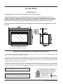
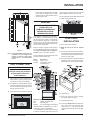
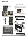
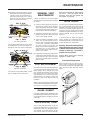
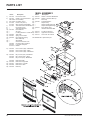
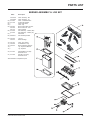
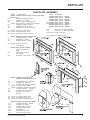
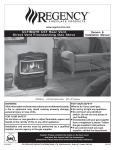
www.hampton-fire.com
www.regency-fire.com
U32 Gas Insert
Owners &
Installation Manual
MODELS: U32-NG2 Natural Gas U32-LP2 Propane
WARNING:
FOR YOUR SAFETY
Improper installation, adjustment, alteration, service or main- What to do if you smell gas:
tenance can cause injury or property damage. Refer to this
Do not try to light any appliance
manual. For assistance or additional information consult an
Do not touch any electrical switch:
authorized installer, service agency or the gas supplier.
do not use any phone in your
building.
FOR YOUR SAFETY
Immediately call your gas supplier
Do not store or use gasoline or other flammable vapours and
from a neighbour's phone. Follow
liquids in the vicinity of this or any other appliance.
the gas supplier's instructions.
If you cannot reach your gas
Installation and service must be performed by an authorized
supplier, call the fire department.
installer, service agency or the gas supplier.
Tested by:
Installer: Please complete the details on the back cover
and leave this manual with the homeowner.
Homeowner: Please keep these instructions for future reference.
918-011a
FPI FIREPLACE PRODUCTS INTERNATIONAL LTD. 6988 Venture St., Delta, BC Canada, V4G 1H4
10/08/03
FPI GAS INSERT
TO THE NEW OWNER
Congratulations! You are the owner of a state-of-the-art Gas Insert by FPI.
The FPI Gas Insert Series of hand crafted appliances has been designed to provide you with all the
warmth and charm of a fireplace, at the flick of a switch. The models U32-NG2 and U32-LP2 of this series
have been approved by Warnock Hersey for both safety and efficiency. As it also bears our own mark, it
promises to provide you with economy, comfort and security for many trouble free years to follow.
Please take a moment now to acquaint yourself with these instructions and the many features of your FPI
Fireplace.
Note: Oversize faceplate is 44" x 28"
INFORMATION FOR MOBILE/MANUFACTURED HOMES AFTER FIRST SALE
This FPI product has been tested and listed by Warnock Hersey as a Direct Vent Wall Furnace to the following standards: CAN/
CGA-2.17-M91, and ANSI Z21.88-1998/CSA 2.33-M98.
This Direct Vent System Appliance must be installed in accordance with the manufacturer's installation instructions and the
Manufactured Home Construction and Safety Standard, Title 24 CFR, Part 3280, or the current Standard of Fire Safety Criteria for
Manufactured Home Installations, Sites, and Communities ANSI/NFPA 501A, and with CAN/CSA Z240-MH Mobile Home Standard
in Canada. See page 6 for additional requirements.
This appliance installation must comply with the manufacturer's installation instructions and local codes, if any. In the absence
of local codes follow the current National Fuel Gas Code, ANSI Z223.1 and the current National Electrical Code ANSI/NFPA 70 in
the U.S.A., and the current CAN/CGA B149 Gas Installation Code and the current Canadian Electrical Code CSA C22.1 in Canada.
This FPI Mobile/Manufactured Home Listed appliance
comes factory equipped with a means to secure the unit.
This FPI Mobile/Manufactured Home listed appliance comes
equipped with a dedicated #8 ground lug to which an 18 gauge
copper wire from the steel chassis ground must be attached.
2
U32-2 FPI Direct Vent Gas Insert
TABLE OF CONTENTS
FPI GAS INSERT
Unit Dimensions ................................................................... 2
Operating Instructions
Safety Label ......................................................................... 4
Operating Instructions ......................................................... 17
Lighting Procedure .............................................................. 17
Shutdown Procedure ........................................................... 17
First Fire
....................................................................... 17
Automatic Convection Fan Operation ................................. 17
Normal Operating Sounds of Gas Appliances ................... 17
Copy of Lighting Instruction Plate ....................................... 18
Installation
For Your Safety ...................................................................... 5
Specifications ........................................................................ 5
Gas Pressure Testing ........................................................... 5
Installation into a Solid Fuel Burning Fireplace or
Factory Built Fireplace .................................................... 5
General Safety Information .................................................... 5
Installation Checklist ............................................................. 5
Manufactured Mobile Home Additional Requirements ........ 6
Materials Required ................................................................ 6
Minimum Fireplace Clearances ........................................... 6
Clearances to Combustibles ................................................ 6
Gas Connection .................................................................... 7
Venting
......................................................................... 7
- Flue Liner Installation .................................................. 7
Gas Pressure Test ................................................................ 8
Gas Insert Aeration System .................................................. 8
Optional Brick Panel .............................................................. 8
Log Installation ...................................................................... 9
Faceplate & Trim ................................................................. 10
Standard Flush Door ........................................................... 11
Optional Flush Trim ............................................................. 11
Optional Door Fire Screen .................................................. 11
Flush Louvers ...................................................................... 11
Optional Bay Door ............................................................... 12
Optional Bay Trim ................................................................ 12
Bay Louvers ....................................................................... 12
Hampton Cast Faceplate Installation ................................. 13
Hampton Cast Faceplate Grill ............................................ 14
Optional Wall Thermostat ................................................... 15
Optional Remote Control .................................................... 15
Final Check ....................................................................... 15
Wiring Diagram ................................................................... 16
U32-2 FPI Direct Vent Gas Insert
Maintenance
Maintenance ....................................................................... 18
General Vent Maintenance .................................................. 19
Log Replacement ................................................................ 19
Glass Gasket ....................................................................... 19
Gold Plated Trim ................................................................. 19
Door Glass ....................................................................... 19
- Flush Glass Replacement ......................................... 19
- Bay Glass Removal ................................................... 19
Fan Maintenance ................................................................. 20
Valve Removal & Replacement .......................................... 21
Parts List
....................................................................... 22
Warranty
Warranty
....................................................................... 27
3
SAFETY LABEL
This is a copy of the labels that accompany
each U32-2 Gas Insert. We have printed a copy
of the contents here for your review. The
safety label is located on a plate inside the base
of the unit visible when the bottom louver is
opened.
NOTE: FPI units are constantly being improved. Check the label on the unit and if
there is a difference, the label on the unit
is the correct one.
For the State of Massachusetts, installation and repair must be done by a plumber or gasfitter licensed in
the Commonwealth of Massachusetts.
For the State of Massachusetts, flexible connectors shall not exceed 36 inches in length.
For the State of Massachusetts, the appliances individual manual shut-off must be a t-handle type valve.
4
U32-2 FPI Direct Vent Gas Insert
INSTALLATION
IMPORTANT:
SAVE THESE
INSTRUCTIONS
The FPI Gas Insert must be installed in accordance with these instructions. Carefully read all
the instructions in this manual first. Consult the
building authority having jurisdiction to determine the need for a permit prior to starting the
installation.
NOTE: Failure to follow the instructions could
cause a malfunction of the heater which could
result in death, serious bodily injury, and/or
property damage. Failure to follow these instructions may also void your fire insurance
and/or warranty.
FOR YOUR SAFETY
This appliance requires air for proper combustion. Always provide adequate combustion
and ventilation air. Follow instructions and
information in CAN/CGA B149 (in Canada) or
the National Fuel Gas Code ANSI Z223.1 (in the
USA), regarding requirements for combustion
and ventilation air.
SPECIFICATIONS
At pressures over 1/2 psig, the pipe to the unit
must be disconnected.
Gas Input Capacity:
Natural Gas 30,000
Propane
30,000
Min. Input
Natural Gas
Propane
15,300
15,000
Btu/h
Btu/h
Btu/h
Btu/h
Fuels: Approved for use with both natural gas,
and propane. Approved as is for use at 0' to
4,500' (0-1370m).
Electrical: 120V
A.C. system.
Circulation Fan: Variable speed, 110 CFM.
Log Set: Ceramic fibre, 7 per set.
Vent System:
3" co-linear aluminum flex.
The efficiency rating of the appliance is a
product thermal efficiency rating determined
under continuous operating conditions and was
determined independent of any installed system.
U32-2 FPI Direct Vent Gas Insert
GAS PRESSURE
TESTING
The appliance must be isolated from the gas
supply piping system by closing its individual
manual shut off valve during any pressure
testing of the gas supply piping system at test
pressures equal to or less than
1/2 psig. (3.45 kPa).
INSTALLATION INTO A
SOLID FUEL BURNING
FIREPLACE OR
FACTORY BUILT
FIREPLACE
The U32-2 Gas Inserts have been tested and
approved to be vented into any masonry fireplace or approved solid fuel burning factory
built fireplace that will allow the insert to physically fit into the firebox. Refer to page 6 for
minimum fireplace clearances.
If the factory built fireplace* height is too low for
your Insert, you may remove the smoke baffle
plate, damper, refractory (firebricks), glass
doors, screen rails, screen mesh and log grates
from the factory built fireplace as long as these
items are saved and are reinstalled in the event
that the Insert is removed.
Smoke shelves, shields and baffles may be
removed if attached by mechanical fasteners.
If any part is removed it must not weaken the
structural integrity of the factory built fireplace.
NOTE: Any alterations made to the listed solid
fuel burning factory built fireplace may void the
listing of the fireplace.
*Check with your local inspector before commencing with this installation.
BEFORE YOU START
Safe installation and operation of this appliance
requires common sense, however, we are
required by the Canadian Safety Standards
and ANSI Standards to make you aware of the
following:
General Safety Information
1) The appliance installation must conform
with local codes or in the absence of local
codes, with CAN/CGA B149 (in Canada) or
the National Fuel Gas Code ANSI Z223.1 in
the U.S.A. This appliance should be installed by a qualified gas fitter technician
only.
2) Installation and repair should be done
by a qualified service person.
3) The appliance should be inspected before
use and at least annually by a professional
service person. More frequent cleaning
may be required due to excessive lint from
carpeting, bedding material, animal hair,
etc. It is imperative that control compartments, burners and circulating air passageways of the appliance be kept clean.
4) See general construction and assembly
instructions. This appliance may only be
installed in a vented, noncombustible fireplace.
5) This appliance is Listed for bedroom installations when used with a Listed Millivolt
Thermostat. Some areas may have further
requirements, check local codes before
installation.
6) Always connect this insert to a vent system
venting to the outside of the building envelope. Never vent to another room or inside
a building. Make sure that the vent is
properly sized and is of adequate height to
provide the proper draft.
7) Inspect the venting system annually for
blockage and any signs of deterioration.
8) Any glass removed for servicing must be
replaced prior to operating the appliance.
9) To prevent injury, do not allow anyone who
is unfamiliar with the operation to use the
fireplace.
10) Due to high temperatures, the appliance
should be located out of high traffic areas
and away from furniture and draperies.
Children and adults should be alerted to the
hazards of high surface temperatures,
especially the fireplace glass and gold trims,
and should stay away to avoid burns or
clothing ignition. Young children should be
carefully supervised when they are in the
same room as the appliance. Clothing or
other flammable material should not be placed
on or near the appliance.
Emissions from burning wood or gas could
contain chemicals known to the State of
California to cause cancer, birth defects or
other reproductive harm.
INSTALLATION
CHECKLIST
Before installing vent system ensure that the
damper plate is open and secure to prevent the
damper plate from falling down and crushing
the liner.
The FPI Gas Insert is installed as listed below.
5
INSTALLATION
1) Check all clearances to combustibles, page
6.
2) Make the gas connection. See page 7.
3) Install the 3" flue liner to the sliding connector plate. See page 7.
4) Slide the unit half way into the fireplace.
5) Pull the vent connector plate through the
tapered brackets and fasten to the front
plate. See page 7.
MATERIALS REQUIRED
No electrical power supply is required for the
gas control to operate. A 120 Volt AC power
cord is hooked up to the fan. Plug the 3 wire
cord into a suitable receptacle. Do not cut the
ground terminal off under any circumstances. When connected with 120 volts, the
appliance must be electrically grounded in accordance with local codes, current version of
CSA C22.1 (in Canada) or in the absence of
local codes, with the National Electrical Code
ANSI/NFPA 70-1987.
6) Slide the unit fully into the fireplace.
7) Test gas pressure, page 8. Check aeration
system, page 8.
8) Install the optional brick panels. See page 8.
9) Install the log set. See page 9.
10) Assemble and install the faceplate and trim.
See page 10.
11) Install the glass front (flush or bay). See
pages 10 and 11.
NOTE: This unit is equipped with a heat
sensor thermodisc which will
prevent the blower from operating until the unit reaches the correct temperature.
MINIMUM FIREPLACE
DIMENSIONS
CLEARANCES TO
COMBUSTIBLES
Minimum Clearances to Combustibles
From Unit
A
10" / 255 mm
B
47.5" / 1205 mm
C
see Dia. 2 & 3
Sides
Ceiling
Mantel
From Standard Surround (26" x 40")
Sides
D
4" / 100 mm
Ceiling
E
41.5" / 1055 mm
Mantel
see Dia. 2 & 3
Max. Mantle Depth G
H
I
J
12" / 305 mm
(see Dia. 2)
0" / 0 mm
16" / 405 mm
40" / 1015 mm
Min. Alcove Width K
Max. Alcove Depth L
48" / 1220 mm
36" / 915 mm
Hearth Height
Hearth Depth
Hearth Width
The minimum fireplace clearances & dimensions for the FPI gas insert are shown in the
following diagrams:
12) Install optional glass trim, or door fire
screens. See pages 11 and 12.
13) Install both louvers (flush or bay). See
pages 11 and 12.
14) Install optional remote control or wall thermostat, pages 15.
15) Final check: Before leaving this unit with
the customer, the installer must ensure that
the appliance is firing correctly. This includes:
a) Clocking the appliance to ensure the
correct firing rate.
Diagram 1
b) Adjusting the primary air, if required, to
ensure that the flame does not carbon.
See page 8.
Combustible Mantel Clearances
with Bay & Flush Louvers in
Masonry and Factory Built
Fireplace Installation
c) Ensuring that the appliance is venting
correctly.
MANUFACTURED
MOBILE HOME
ADDITIONAL
REQUIREMENTS
1) Ensure that structural members are not cut
or weakened during installation.
2) Ensure proper grounding using the #8
ground lug provided.
3) Appliance must be anchored to the floor
with the supplied anchoring methods.
*Note: If you are installing the Molded
Faceplate, the minimum fireplace dimensions are as follows:
Width (at front): 29" (737mm)
Depth:
15" (381mm)
Diagram 2
6
U32-2 FPI Direct Vent Gas Insert
INSTALLATION
pass through the chimney above the appliance. Move the appliance into the exact
location where it is to be installed. Ensure
that the Insert is level.
mend using the Simpson Dura-Vent System
(923GK adapter and 991 high-wind cap).
The Air Intake pipe must be attached to the inlet
air collar of the termination cap.
VENTING
THE APPLIANCE MUST NOT BE
CONNECTED TO A
CHIMNEY FLUE SERVING A
SEPARATE SOLID FUEL
BURNING APPLIANCE.
This appliance is designed to be attached to
two 3" (76mm) co-linear aluminium flex running
the full length of the chimney. The flue length
must be a minimum length of 8 ' (2.44m) and a
maximum of 35' (10.7m). See chart below for
minimum distances from roof. Periodically check
that the vent is unrestricted.
Diagram 3
Note: A noncombustible mantel may be
installed at a lower height if the
framing is made of metal studs
covered with a noncombustible
board.
GAS CONNECTION
Masonry chimneys may take various contours
which the flexible liner will accommodate. However, keep the flexible liner as straight as
possible, avoid unnecessary bending.
FLUE LINER
INSTALLATION
1) Cut the flex liner as required.
2) Mark the end of one liner to indicate
Inlet.
The Air Intake pipe must be attached to the inlet
air collar of the termination cap.
3) Connect the other end of the above liner to
the inlet side of the termination adaptor, seal
connection with high temperature silicone.
Secure with gear clamp.
Part #
948-305
946-529
4) Connect the 2nd liner to the exhaust side of
the adaptor, seal connection with high temperature silicone. Secure with gear clamp.
Description
3" Flex - 35 ft.
Co-linear DV Vertical
Termination Cap
GAS CONNECTION WARNING:
Only persons licensed to work
with gas piping may make the
necessary gas connections
to this appliance.
1) If the appliance is to be installed into an
existing chimney system, thoroughly clean
the masonry or factory built fireplace.
2) The appliance is provided with an opening
on the left hand side of the control compartment. A 3/8" NPT gas supply pipe must be
brought near this inlet hole.
3) Locate the center point where the vent will
5) Install flashing.
6) Insert both liners into chimney, passing
through the damper opening.
Alternate Approved Caps
980
Vertical Termination Cap
991**
High Wind Cap
923GK**
3" Co-linear Adaptor with flashing
*Recommended for installations up to and including 25 ft. (7.6m) in length/height.
** For installations in excess of 25 ft. (7.6m) or
in areas of consistently high winds, we recomU32-2 FPI Direct Vent Gas Insert
7) Install termination cap.
8) Connect the marked end of the liner to the
inlet collar of the vent connector plate
marked with an "I", seal connection with
high temperature silicone. Secure with gear
clamp.
7
INSTALLATION
2) Loosen the "IN" and/or "OUT" pressure
tap(s), turning counterclockwise with a 1/
8" wide flat screwdriver.
3) Attach manometer to "IN" and/or "OUT"
pressure tap(s) using a 5/16" ID hose.
4) Light the pilot and turn the valve to "ON"
position.
5) The pressure check should be carried out
with the unit burning and the setting should
be within the limits specified on the safety
label.
9) Connect the 2nd liner to the exhaust collar
marked with an "E", seal connection with
high temperature silicone. Secure with gear
clamp.
1) Unwrap the brick pattern panels from the
protective wrapping.
2) Remove the glass front if it is already
installed, see page 11.
3) Put the rear brick panel flat against the back
of the unit.
6) When finished reading manometer, turn off
the gas valve, disconnect the hose and
tighten the screw (clockwise) with a 1/8"
flat screwdriver. Note: Screw should be
snug, but do not over tighten.
GAS INSERT
AERATION SYSTEM
The air shutter can be adjusted by moving the
adjusting wire up or down. The wire is accessed through the bottom louver opening.
Open the air shutter for a blue flame or close
for a yellower flame. The burner aeration is
factory set but may need adjusting due to either
the local gas supply or altitude.
NOTE: 1) Final gas connection should be made
after unit is in place to avoid damage to
line when pushing the unit into position.
OPTIONAL
BRICK PANEL
4) Before installing the side brick panels,
loosen the screws for the brick tabs enough
so that you can slide the brick tabs on to the
screws easily but that the tabs are secure.
For the location of the side brick tab screws
see diagram 1.
Minimum Air Shutter Opening:
3/16"
Natural Gas
1/4"
Propane
2) Mill-pac may be used instead of high
temperature silicone and screws may
be used instead of gear clamps at
connections of liner to inlet and vent
collars.
GAS PIPE
PRESSURE TESTING
Diagram 1
The appliance must be isolated from the gas
supply piping system by closing its individual
manual shut-off valve during any pressure
testing of the gas supply piping system at test
pressures equal to or less than 1/2 psig. (3.45
kPa). Disconnect piping from valve at pressures over 1/2 psig.
The manifold pressure is controlled by a regulator built into the gas control, and should be
checked at the pressure test point.
Note: To properly check gas pressure,
both inlet and manifold pressures
should be checked using the valve
pressure ports on the valve.
1) Make sure the valve is in the "OFF" position.
Aeration Adjustment Wire
PULL= Open
PUSH = Close
5) Remove the brick tabs and slide the side
brick panels into position. See diagram 1.
Install the brick tabs. See diagram 2.
CAUTION: Carbon will be produced if air
shutter is closed too much.
Note: any damage due to carboning resulting from improperly setting the aeration controls is NOT covered under
warranty.
Note: Aeration Adjustment should only
be performed by an authorized FPI
Installer at the time of installation
or service.
Diagram 2
8
U32-2 FPI Direct Vent Gas Insert
INSTALLATION
LOG SET
INSTALLATION
3) Place Rear Log A)02-43 on the two pins on
the rear log support.
Read the instructions below carefully
and refer to the diagrams. If logs are
broken do not use the unit until they are
replaced. Broken logs can interfere with
the pilot operation.
6) Place the Left Top Log D)02-46 on the pin on
Log C)02-56 and on top of the cutout on Log
A)02-43.
A)02-43
D)02-46
A)02-43
The gas log kit contains the following:
C)02-56
a)
b)
c)
d)
e)
f)
g)
h)
i)
j)
02-43
02-45
02-56
02-46
02-47
02-48
02-44
Rear Log
Front Right Log
Middle Left Log
Left Top Log
Center Log
Middle Right Log
Front Left Log
Embers
Rockwool
Vermiculite
902-227
902-229
902-230
902-231
902-232
902-226
902-228
902-154
902-153
902-179/21
Pins on Rear Log Support
Pin
4) Place Front Right Log B)02-45 on the two
pins as shown.
Note: Install Optional Brick Panels prior
to installing logs.
Cutout
7) Place the notch in Center Log E)02-47 over
Log B)02-45 and across the cutout on Log
A)02-43.
E)02-47
B)02-45
A)02-43
B)02-45
5) Place the Middle Left Log C)02-56 on the
two pins as shown.
The "02" refer numbers (i.e. 02-43) are
molded into the rear of each log.
Notch
Cutout
C)02-56
Logs D)02-46 and E)02-47 in position.
1) Carefully remove the logs from the box and
unwrap them. The logs are fragile, handle
with care - do not force into position.
8) Position notch in Front Right Log F)02-48 on
Log E)02-47 and push the bottom right edge
against the bracket on the burner tray and
the front edge of the rear burner.
2) Sprinkle the vermiculite around the firebox
base. Take some of the embers (approx.
1/3 of the bag) and sprinkle over the vermiculite.
F)02-48
E)0
2-4
7
Logs A)02-43, C)02-56,
and B)02-45 in position
B)02-45
Notch
Vermiculite and
embers.
Bracket
Vermiculite and
Vermiculite and
embers.
embers.
U32-2 FPI Direct Vent Gas Insert
9
INSTALLATION
B)02-45
A)02-43
F)02-48
FACEPLATE & TRIM
INSTALLATION
1) Lay the faceplate panels flat, face down
on something soft so they don't scratch.
Side View
Front edge of
rear burner
Bracket
The bottom right edge of Log F)02-48 must
sit snugly against the bracket and the front
edge of the rear burner.
2) Take the top faceplate and align the holes
in it with the holes in the side panels. Using
the screws provided, attach from the top
of the panel (the holes in the top panel are
slightly larger than the holes in the side
panel to facilitate easier installation). Diagram 1.
Rear View: Trim Assembly
Diagram 2
9) Place Front Left Log G)02-44 onto the 2
front pins as shown.
5) Connect the fan switch wires by taking the
black and red wires with the male ends (in
the grey harness) and connect them with
the wire connectors from the fan speed
control.
G)02-44
6) Connect the ON/OFF switch wires by taking the black and red wires with the female
ends and connect them to the ON/OFF
switch.
7) Tuck the wires into the faceplate to keep
them away from the insert using the clip
provided. Attach the clip to the rear of the
faceplate to ensure that the wires do not
touch the side of the unit. Diagram 3.
10) Place the embers and Rockwool on the
exposed front burner tray.
Rear View: Faceplate Assembly
Diagram 1
11) Test fire to ensure proper light off (make
sure flame flows smoothly from one end of
burner to the other. If there is any flame
hesitation, check that area for any blockage of the burner port.
12) Install flush glass and optional bay glass as
per instructions in this manual.
46
C)02-56
E)02-4
D)
02
2-4 A)02-43
8
7
F)0
B)02-45
Hint: Don't tighten the screws down completely at this point, continue on with
steps 3 and 4 and do a trial fit to the unit.
Make any necessary adjustments and when
it fits properly then tighten down the screws.
Hearth Trim Option: Hearth Trim is an
option that can be used to finish off the
installation when the bottom of the fireplace
is higher than the hearth or to raise the
fireplace. Attach the Hearth Trim to the
bottom of the faceplate side panels with the
screws provided. See Diagram 1.
8) The power cord should be run behind the
faceplate panel.
3) Using the connectors provided, join the left
side trim (with the ON/OFF switch) to the top
trim. Diagram 2. Connect the right side trim
to the top trim.
9) Attach the brass trim to the faceplate by
drilling a 1/8" hole through into the faceplate
using the hole in the trim as a guide. Fasten
the trim to the faceplate panels using the
plated screws. Diagram 4.
4) Place the trim on the assembled faceplate
panels, aligning the wire connections from
the switches with the notch on the left side
panel.
10) Attach the faceplate panels to the insert
body using the 4 remaining black screws.
Diagram 5.
G)02-44
10
Diagram 3
U32-2 FPI Direct Vent Gas Insert
INSTALLATION
OPTIONAL DOUBLE
DOOR FIRE SCREEN
1) Pull out the top
louver.
Diagram 2
Use the hook to pull the spring out until you can
put the hook into the slot on the bottom door
bracket. Repeat for
2nd spring.
See diagram 3.
Diagram 4
Diagram 3
To remove the flush door, reverse the above
steps.
2) Center the
screen door
and hook over
the
flush
door.
3) Open the screen door(s) and secure the
screen door to the flush door front with 2
clips on the bottom left and right side.
NOTE: The chain must rest on TOP of the gas
inlet pipe never under it.
Diagram 5
11) Push the Regency logo plate into the two
holes in the bottom left corner of the faceplate.
STANDARD
FLUSH DOOR
The standard flush door comes with a black
frame. To install the frame, simply hook the top
door flange onto the top of the unit and swing
the door towards the unit, diagram 1. Be careful
that the glass gasket does not roll up; there
must be a gap between the gasket and the door
lip to ensure that the door sits securely on the
unit. Diagram 2.
Clip locations
OPTIONAL
FLUSH TRIM
Attach 2 round magnets to the back of the top
trim piece and the other 2 to the bottom trim
piece, then attach trim to the top and bottom of
Flush door.
Clip installed
on right side.
FLUSH LOUVERS
1) The top louver is held in place by friction fit,
if the louver needs to be adjusted; bend the
bracket out as shown in the diagram.
Diagram 1a
Note: Top and bottom louvers are different.
Diagram 1b
U32-2 FPI Direct Vent Gas Insert
2) The bottom louver has a hinge that is attached (2 screws per hinge) to the lip on
bottom of the unit.
11
INSTALLATION
OPTIONAL BAY DOOR
The Bay louvers MUST be used
with the Bay glass option.
The optional Bay door is an overlay on the
flush front. The standard flush door and
glass must remain on the unit. Hook the top of
the bay door over the flush door flange and
swing the bottom against the bottom flange of
the flush door. Press down on the Bay Bottom
bracket and push in until it clips behind the
bottom of the flush front.
Removing Bay Door
To remove only the Bay Door - use a screwdriver to unclip the Bay Bottom bracket from the
flush door and then swing up and unhook from
the top flush door flange.
To remove the Bay Door & the Flush Front
together, pull the hook from the slot in the
bottom door bracket under the unit (see Standard Flush Door instructions above). Then pull
the Bay Door and Flush door out and lift off of
the flange at the top of the unit.
BAY LOUVERS
1) Install top louver by sliding the two bracket
clips into the brackets located on top of the
bay door. See below. The fitted louver
leaves a small gap between faceplate bottom and louver top.
Note: If any maintenance etc. must be
done in the firebox, first remove
the Bay louvers and door.
OPTIONAL BAY TRIM
Attach 4 supplied magnets each to the back of
the top and bottom trim pieces, and attach trim
to the top and bottom of Bay door.
Slide the valve extension knobs onto the valve
knobs. Match each extension knob with the
corresponding valve knob. Extension knobs
are for Bay Front installations only.
Robert Shaw Extension
knobs for Bay Front only.
12
2) Install bottom louver by sliding the two
bracket clips into the brackets located underneath the bay door. Secure with 1 screw
into each Bottom Louver Mounting Bracket
as per diagram below. Use the bottom hole
in the bracket.
3) Slide the Robert Shaw valve extension
knobs onto the valve knobs. Match the
correct ext. knob with the valve knob.
U32-2 FPI Direct Vent Gas Insert
INSTALLATION
HAMPTON CAST
FACEPLATE INSTALLATION
NOTE: Do not install Cast Faceplate when unit is installed into
a Zero Clearance Unit.
1) Lay the faceplate panels flat, face down on something soft so they
don't scratch.
2) Attach the side filler brackets to the left and right sides using 3
screws and washer per side.
NOTE: There are filler brackets specifically for each side. The
way to differentiate this is that on the side of the brackets
there are 2 mounting holes. The side where there is a 7/16"
gap from the top of the bracket to the mounting hole, must
face the top.
3) Attach the right and left cast sides to the top using 2 screws per
side.
5) Connect the ON/OFF switch
wires by taking the black and
red wires with the blue female
ends thru the hole provided
and connecting them to the
ON/OFF switch.
6) Connect the fan switch wires
by taking the black and red
wires with the male ends (in
the grey harness) thru the
hole provided and connect
them with the wire connectors from the fan speed control.
7) Insert wires into the strain relief and install into switch box
assembly.
8) Place the switch box assembly over the boss on the rear left side
piece and secure with one screw.
Switch Box Assembly
Boss on rear left side
piece.
Ensure that the top
and sides are
aligned.
4) Use a measuring tape to ensure that the distance between the left
and right side pieces is 28" (711mm).
9) Tuck the wires into the faceplate to keep
them away from the insert using the clip
provided. Attach the clip to the rear of the
faceplate to ensure that the wires do not
touch the side of the unit.
10) The power cord should be run behind the
faceplate panel.
28"
U32-2 FPI Direct Vent Gas Insert
13
INSTALLATION
11) Mount the cast faceplate panels onto the insert body, sliding the
side filler brackets into the space between the glass and the
firebox. Secure using the 4 remaining black screws, 2 per side.
Slide side filler
bracket into gap
between glass and
fire box.
HAMPTON CAST FACEPLATE
GRILL INSTALLATION
1) Install logs and flush glass before going on to the next step. See
manual for details.
2) Before the grills are inserted onto the firebox, the U32 grill stop
bracket needs to be inserted in the bottom left corner just under the
firebox.
U32 Grill
Stop
Bracket
3) The top louver, shown in diagram 1, is held in place by friction fit, if
the louver needs to be adjusted; bend the convex bracket out as
shown in diagram 2.
4) The bottom louver has 2 hinges that are attached
(2 screws per hinge) to the lip on bottom of the unit.
12) Install the glass trim by inserting the side hooks on the glass trim
into the 4 slots between the faceplate and the glass. Push the glass
trim down firmly with both hands to lock into place.
Note: The top louver should be placed with the
curved cut-out facing up.
Side Hook
Diagram 1
Slots
Diagram 2
13) To put on the Hampton logo, peel the sticker from the back of the
logo and place it centered on the bottom left hand corner of the
faceplate.
Diagram 3
Hampton Logo
14
Left Hand
Side Faceplate
Note: The top and bottom grills and brackets
are different.
U32-2 FPI Direct Vent Gas Insert
INSTALLATION
OPTIONAL WALL
THERMOSTAT
OPTIONAL REMOTE
CONTROL
A wall thermostat may be installed if desired,
follow the wiring diagram below. FPI offers an
optional programmable thermostat but any 250750 millivolt rated non-anticipator type thermostat that is CSA, ULC or UL approved may be
used.
Use the FPI Remote Control Kit approved for
this unit. Use of other systems may void your
warranty.
Thermostat Wire Table
Recommended Maximum Lead Length
(Two-Wire) When Using Wall
Thermostat (CP-2 System)
Wire Size
14 GA.
16 GA.
18 GA.
20 GA.
22 GA.
Max. Length
50 Ft.
32 Ft.
20 Ft.
12 Ft.
9 Ft.
CAUTION
Do not connect the millivolt wall
thermostat wires
to the 120V wires.
U32-2 FPI Direct Vent Gas Insert
The remote control kit comes with a hand held
transmitter, a receiver and a wall mounting
plate.
1) Choose a convenient location on the wall
to install the receiver and the receptacle
box (protection from extreme heat is very
important). Run wires from the fireplace to
that location. Use Thermostat Wire Table.
2) Connect the wires as per the wiring diagrams below.
CAUTION
Do not connect the millivolt
remote control wires for
to the 120V wires.
FINAL CHECK
Before leaving this unit with the customer, the
installer must ensure that the appliance is firing
correctly. This includes:
1) Clocking the appliance to ensure the correct firing rate (rate noted on label) at 15
minutes.
2) If required, adjusting the primary air to
ensure that the flame does not carbon. First
allow the unit to burn for 15 min. to stabilize.
3) Check for proper draft.
CAUTION
Any alteration to the product that
causes sooting or carboning that
results in damage to the exterior
facia is not the responsibility of
the manufacturer.
3) Install 3 AAA alkaline batteries in transmitter
and 4 AA alkaline batteries in the receiver.
Install the receiver and its cover in the wall.
Switch the remote receiver to "remote"
mode. The remote control is now ready for
operation.
15
INSTALLATION
WIRING DIAGRAM
This heater does not require a 120V A.C. supply for operation. In case of a power failure, the burner switch and the optional remote control/thermostat
will continue to operate. However, a 120V A.C. power supply is needed for the fan/blower operation.
CAUTION: Label all wires prior to
disconnection when servicing controls. Wiring errors can cause improper and dangerous operation.
Caution: Ensure that the wires do not
touch any hot surfaces and are away
from sharp edges.
WARNING:
Electrical Grounding Instructions
This appliance is equipped with a three pronged (grounding) plug for your protection
against shock hazard and should be plugged directly into a properly grounded threeprong receptacle. Do not cut or remove the grounding prong from this plug.
16
U32-2 FPI Direct Vent Gas Insert
OPERATING INSTRUCTIONS
Before operating this appliance, proceed
through the following check list.
4) Wait five minutes to allow gas, that may have
accumulated in the main burner compartment, to escape. If you do smell gas, follow
the instructions on the front of this manual.
If you don't smell gas continue on to the next
step.
Note: When the glass is cold and the
appliance is lit, it may cause condensation and fog the glass. This
condensation is normal and will
disappear in a few minutes as the
glass heats up.
1) Read and understand these Instructions
before operating this appliance.
5) Turn the gas control counter clockwise to
"PILOT".
2) Check to see that all wiring is correct and
enclosed to prevent possible shock.
6) Push in control knob all the way and hold in.
Continually push and release the black button on spark igniter until pilot lights. Continue
to hold the control knob in for approximately
one minute, then release the gas control
knob. The pilot flame should continue to
burn. If the pilot does not remain lit, repeat
operation allowing a longer period before
releasing gas control knob.
DO NOT BURN THE APPLIANCE
WITHOUT THE GLASS FRONT IN
PLACE.
OPERATING
INSTRUCTIONS
3) Check to ensure there are no gas leaks.
4) Make sure the glass door is in place. Never
operate the appliance with the door glass
removed.
5) Verify that all venting and the cap is unobstructed.
6) Verify log placement. If the pilot cannot be
seen when lighting the unit - the logs or the
embers have been incorrectly positioned.
7) The unit should never be turned off and on
again without a minimum of a 60 second
wait.
8) When lighting the appliance, the inside of
the glass may fog up. This will burn off after
a few minutes of operation.
DO NOT BURN THE APPLIANCE
WITH THE GLASS ASSEMBLY REMOVED.
7) Turn gas control knob counter clockwise to
"ON".
8) Use the rocker switch to operate main
burner.
9) Rotate the variable flame control to adjust
the flame height higher or lower.
10) Close the bottom louver assembly.
SHUTDOWN
PROCEDURE
1) Use the rocker switch to turn off the main
burner.
2) Open the bottom louver assembly.
3) Push in the gas control knob slightly and turn
clockwise to "OFF". Do not force.
4) Disconnect all electric power and gas to the
appliance if service is to be performed.
FIRST FIRE
LIGHTING
PROCEDURE
IMPORTANT: Gas cock knob cannot be
turned from "PILOT" to "OFF" unless it is
partially depressed.
1) Open the bottom louver assembly
2) If the control knob is in the "OFF" position
proceed to Step 5.
3) Push in gas control knob slightly and turn
clockwise to "OFF". Knob cannot be turned
from "PILOT" to "OFF" unless knob is pushed
in slightly. Do not force.
U32-2 FPI Direct Vent Gas Insert
The first fire in your stove is part of the paint
curing process. To ensure that the paint is
properly cured, it is recommended that you burn
your fireplace for at least four (4) hours the first
time you use it with the fan on. When first
operated, the unit will release an odour caused
by the curing of the paint, the burning off of any
oils remaining from manufacturing. Smoke detectors in the house may go off at this time. Open
a few windows to ventilate the room for a
couple of hours.
The glass panel may require cleaning
after the unit has cooled down. DO
NOT ATTEMPT TO CLEAN THE
GLASS WHILE IT IS HOT.
During the first few fires, a white film
may develop on the glass front as part
of the curing process. The glass should
be cleaned or the film will bake on and
become very difficult to remove. Use
a non-abrasive cleaner and NEVER clean
the glass while it is hot.
AUTOMATIC
CONVECTION FAN
OPERATION
The fan operates automatically, turn the knob
on the side of the faceplate to adjust to the
desired speed. The fan will turn on as the stove
comes up to operating temperature. After the
unit has been turned off and the unit cooled to
below a useful heat output range the fan will
shut off automatically.
NORMAL OPERATING
SOUNDS OF
GAS APPLIANCES
It is possible that you will hear some sounds
from your gas appliance. This is perfectly
normal due to the fact that there are various
gauges and types of steel used within your
appliance. Listed below are some examples.
All are normal operating sounds and
should not be considered as defects in your
appliance.
Blower:
FPI gas appliances use high tech blowers to
push heated air farther into the room. It is not
unusual for the fan to make a "whirring" sound
when ON. This sound will increase or decrease in volume depending on the speed
setting of your fan speed control.
Burner Tray:
The burner tray is positioned directly under the
burner tube(s) and logs and is made of a
different gauge material from the rest of the
firebox and body. Therefore, the varying thicknesses of steel will expand and contract at
slightly different rates which can cause "ticking" and "cracking" sounds. You should also
be aware that as there are temperature changes within the unit these sounds will likely reoccur. Again, this is normal for steel fireboxes.
17
OPERATING INSTRUCTIONS
Blower Thermodisc:
When this thermally activated switch turns ON
it will create a small "clicking" sound. This is the
switch contacts closing and is normal.
COPY OF LIGHTING INSTRUCTION PLATE
Pilot Flame:
While the pilot flame is on it can make a very
slight "whisper" sound.
This appliance must be installed in accordance with local codes, if any; if not,
follow the current CAN1-B149/ANSI Z 223.1 (Australia: AG601, New Zealand: NZS 5261)
FOR YOUR SAFETY READ BEFORE LIGHTING
Gas Control Valve:
As the gas control valve turns ON and OFF, a
dull clicking sound may be audible, this is
normal operation of a gas regulator or valve.
Unit Body/Firebox:
Different types and thicknesses of steel will
expand and contract at different rates resulting in some "cracking" and "ticking" sounds will
be heard throughout the cycling process.
MAINTENANCE
INSTRUCTIONS
1) Always turn the gas valve to off before
cleaning. For relighting, refer to lighting
instructions. Keep the burner and control
compartment clean by brushing and vacuuming at least once a year. When cleaning
the logs, use a clean soft paint brush as the
logs are fragile and easily damaged.
2) Clean (never when unit is hot) appliance,
door and louvers with a damp cloth. Never
use an abrasive cleaner. The gold louvers
(and optional gold door) may be scratched
if abrasives are used to clean them.
The heater is finished in a heat resistant
paint and should only be refinished with
heat resistant paint (not with wall paint).
FPI uses StoveBrite Paint - Metallic Black
#6309.
3) Make a periodic check of burner for proper
position and condition. Visually check the
flame of the burner periodically, making
sure the flames are steady; not lifting or
floating. If there is a problem, call a qualified
service person.
4) The appliance and venting system must be
inspected before use, and at least annually, by a qualified field service person, to
ensure that the flow of combustion and
ventilation air is not obstructed.
During the annual service call, the burners
should be removed from the burner tray
and cleaned. Replace the embers but do
not block the pilot.
5) Keep the area near the appliance clear and
free from combustible materials, gasoline
and other flammable vapours and liquids.
18
WARNING: If you do not follow these instructions exactly, a fire or explosion may result
causing property damage, personal injury or loss of life. Improper installation, adjustment,
alteration, service or maintenance can cause injury or property damage. Refer to the
owner’s information manual provided with this appliance. For assistance or additional
information consult a qualified installer, service agency or gas supplier.
A) This appliance has a pilot which must be lighted
by hand, following the instructions below
exactly.
B) BEFORE LIGHTING smell all around the appliance
area for gas. Be sure to smell next to the floor
because some gas is heavier than air and will
settle on the floor.
WHAT TO DO IF YOU SMELL GAS
- Do not try to light any appliance
- Do not touch any electric switch, do not use any
phone in your building
- Immediately call your gas supplier from a
neighbors phone. Follow the gas supplier’s instructions.
- If you cannot reach your gas supplier, call the
fire department.
C) Use only your hand to push in or turn the gas
control knob. Never use tools. If the knob will not
push in or turn by hand, don’t try to repair it, call
a qualified service technician. Force or attempted
repair may result in a fire or explosion.
D) Do not use this appliance if any part has been under
water. Immediately call a qualified service technician to inspect the appliance and to replace any part
of the control system and any gas control which has
been under water.
This appliance needs fresh air for safe operation and
must be installed so there are provisions for adequate
combustion and ventilation air.
CAUTION: Hot while in operation. Do not touch.
Severe Burns may result. Due to high surface
temperatures keep children, clothing and
furniture, gasoline and other liquids having
fammable vapors away. Keep burner and control
compartment clean. See installation and
operating instructions accompanying appliance.
LIGHTING INSTRUCTIONS
STOP! Read the safety information above on this
Release knob and it will pop back up. Pilot should
label.
remain lit. If it goes out, repeat steps 3) and 4).
1) Push in gas control knob slightly and turn
If knob does not pop up when released, stop and
clockwise
to “OFF”. Knob cannot be turned
immediately call your service technician or gas
from “PILOT” to “OFF” unless knob is pushed in
supplier.
If the pilot will not stay lit after several tries, turn the
slightly. Do not force.
2) Wait five (5) minutes to clear out any gas. If you
gas control knob to “OFF” and call your service
then smell gas STOP! follow “B” in the safety
technician or gas supplier.
to “ON”.
information above on this label. If you don’t smell 5) Turn gas control knob counterclockwise
gas, go to the next step.
6) Use rocker switch to operate main burner.
3) Turn knob on gas control counterclockwise
PILOT BURNER
VEILLEUSE
to “PILOT”.
OFF
4) Push in control knob all the way and hold in.
THERMOPILE
Immediately push black button on spark igniter
ELEMENT
until pilot lights. Continue to hold the control
THERMOknob in for about 1/2 minute after the pilot is lit.
ELECTRIQUE
TO TURN OFF GAS APPLIANCE
1) Push in the gas control knob slightly and turn
clockwise
to “OFF”. Do not force.
2) Turn off all electric power to the appliance if
service is to be performed.
You may shut off the pilot during prolonged non use periods to conserve fuel.
DO NOT REMOVE THIS INSTRUCTION PLATE
WARNING: CHILDREN AND
ADULTS SHOULD BE ALERTED TO
THE HAZARDS OF HIGH SURFACE
TEMPERATURE AND SHOULD
STAY AWAY TO AVOID BURNS OR
CLOTHING IGNITION. YOUNG CHILDREN SHOULD BE CAREFULLY SUPERVISED WHEN THEY ARE IN THE
SAME ROOM AS THE APPLIANCE.
CAUTION: ANY SAFETY SCREEN
OR GUARD REMOVED FOR SERVICING AN APPLIANCE MUST BE
REPLACED PRIOR TO OPERATING
THE APPLIANCE.
908-649a
CLOTHING OR OTHER FLAMMABLE MATERIAL SHOULD NOT BE
PLACED ON OR NEAR THE APPLIANCE.
6) Each time the appliance is lit, it may cause
condensation and fog the glass. This condensation and fog is normal and will disappear in a few minutes as the glass heats up.
Never operate the appliance without
the glass properly secured in place or
with the door open.
7) Do not use this appliance if any part has
been under water. Immediately call a qualified service technician to inspect the appliance and to replace nay part of the control
system and any gas control which has been
under water.
U32-2 FPI Direct Vent Gas Insert
MAINTENANCE
8) Periodically check the pilot flames. Correct
flame pattern has three strong blue flames:
1 flowing around the thermopile and 1
around the thermocouple, and 1 flowing
across the rear of the burner (it does not
have to be touching the burner).
GENERAL VENT
MAINTENANCE
Conduct an inspection of the venting system
semi-annually. Recommended areas to inspect
as follows:
1) Check the Venting System for corrosion in
areas that are exposed to the elements.
These will appear as rust spots or streaks,
and in extreme cases, holes. These components should be replaced immediately.
2) Remove the Termination Cap, and shine a
flashlight down the Vent. Remove any bird
nests, or other foreign material.
Top View of pilot flame
Incorrect flame pattern will have small, probably yellow flames, not coming into proper contact with the rear of the burner or thermopile.
3) Check for evidences of excessive condensation, such as water droplets forming in
the inner liner, and subsequently dripping
out the joints, Continuous condensation
can cause corrosion of caps, pipe, and
fittings. It may be caused by having excessive lateral runs, too many elbows, and
exterior portions of the system being exposed to cold weather.
4) Inspect joints, to verify that no pipe sections
or fittings have been disturbed, and consequently loosened. Also check mechanical
supports such as Wall Straps, or plumbers'
tape for rigidity.
LOG REPLACEMENT
Top View of pilot flame
If you have an incorrect flame pattern, contact
your FPI dealer for further instructions.
The unit should never be used with broken logs.
Turn off the gas valve and allow the unit to cool
before opening door to carefully remove the
logs. The pilot light generates enough heat to
burn someone. If for any reason a log should
need replacement, you must use the proper
replacement log. The position of these logs
must be as shown in the diagram under Log
Installation.
Clean any fingerprints off before turning
the unit on.
If the top louvers start to
discolour, check the door gasket seal
and replace if necessary.
DOOR GLASS
Your FPI insert is supplied with high temperature, 5 mm Neoceram ceramic glass that will
withstand the highest heat that your unit will
produce. If your glass requires cleaning, we
recommend using an approved glass cleaner
available at all authorized dealers. Do not use
abrasive materials. Do not clean the glass
when hot.
In the event that you break your glass by
impact, purchase your replacement from an
authorized FPI dealer only, and follow our stepby-step instructions for replacement.
Warning: Do not operate appliance
with glass panels removed, cracked
or broken. Replacement of the glass
should be done by a licensed or
qualified service person.
Caution: Wear gloves when removing
damaged or broken glass.
Flush Glass Replacement
Remove the flush door front (as per instructions on page 11). Remove the 4 glass clips
from each corner. Slide in the new replacement
glass. Push the 4 glass clips back onto the
frame.
NOTE: Improper positioning of logs may create
carbon build-up and will alter the unit’s performance which is not covered under warranty.
GLASS GASKET
If the glass gasket requires replacement use
glass gasket (Part # 936-265) for the Bay Front
and a tadpole gasket for the Flush Front (Part
# 936-155).
GOLD-PLATED TRIM
The 24 carat gold plated finish on the trim
requires little maintenance, and need only be
cleaned with a damp cloth. DO NOT use abrasive materials or chemical cleaners, as they
may harm the finish and void the warranty.
U32-2 FPI Direct Vent Gas Insert
19
MAINTENANCE
Bay Glass Removal
To remove fan:
1) Remove the door from the unit and place on
a soft surface to prevent scratching.
1) Turn the unit off and allow it to cool to room
temperature.
2) Remove the nuts holding the glass retainers
in place.
2) Unplug or disconnect power source to
stove.
3) Remove the glass retainers (sides, top and
bottom).
3) Remove glass front (see page 11).
4) Remove logs and brick panels, if used.
4) Replace the glass. The glass must have
gasketing around it.
5) Reverse the previous steps, replace the
retainers and fasten with the nuts but do not
over tighten, as this can break the glass.
5) Remove the grate by loosening the two
screws and sliding the grate out.
6) Remove the burner/front log support assembly by removing the 2 screws and
lifting it out.
6) Replace door on the stove and check the
seal.
Grate screws
7) Remove the 2 screws holding the Air Intake
Hood to the rear firebox wall and lift out.
Replacing fan:
Reverse above steps. Hint for pushing fan
down onto pins - rub a bit of dish soap on the
grommet so it will slide more easily onto the pin.
Check to make sure the fan is seated properly
on the pins, this is very important- try to move
the fan back and forth, there should be no noise,
if there is check that the grommets haven't come
loose.
FAN MAINTENANCE
If your fan requires maintenance or replacement, access to the fan is through the plate on
the rear wall of the firebox. NOTE: the unit
MUST NOT be operated without the fan
access panel securely in place.
Caution: Label all wires prior to
disconnecting when servicing controls. Wiring errors can cause improper and dangerous operation.
Verify proper operation after servicing.
8) Remove the 10 screws holding the Access
Panel in place.
Seal fan access panel using high temperature
silicone (sparingly).
9) Remove the Fan Air Duct by loosening the
3 screws, squeeze the sides together to
remove.
10) Unplug the wires from the
fan motor (from inside the
stove).
11) Lift Fan Assembly off of
the 2 pins, tip forward
and pull through firebox
opening.
12) Disconnect green wire
from power cord.
20
U32-2 FPI Direct Vent Gas Insert
MAINTENANCE
VALVE REPLACEMENT
2) Reconnect the "gas out" flare fitting with
an 11/16" wrench.
1) Shut off the gas supply.
3) Reconnect the "gas out" flare nut with a .
13/16" wrench.
2) Remove the louvers (and bay door if it is on).
4) Reconnect the quick drop out thermocouple nut with a 9mm wrench.
3) Open the flush door and remove the door.
4) Remove the logs and brick panels.
5) Reconnect the pilot tube nut with a 7/16"
wrench.
5) Remove the grate by loosening the two
screws and sliding the grate out.
6) Scrape off the old gasket from the floor of
the firebox and from the valve tray.
10) Remove the valve by removing the 3
screws in the base of the valve tray.
7) Install a new gasket and reinstall the
valve assembly.
Note: Failure to install a new gasket may
severely affect the appliance performance.
Grate screws
6) Remove the burner assembly by removing
the 2 screws and lifting it out.
8) Reinstall the 11 hold down screws.
9) Hook up the TP, TH, and TP/TH wires to the
appropriate connections on the valve.
10) Reinstall the burner assembly.
11) Undo the pilot tube from the valve with a
7/16" wrench.
12) Undo the quick drop out thermocouple nut on
the valve with a 9mm (metric) wrench.
7) Remove the 2 screws holding the Air Intake
Hood to the rear firebox wall and lift out.
13) Undo the "gas out" flare nut with a 13/16"
wrench.
14) Undo the "gas out" flare fitting with an 11/16"
wrench.
Hint: If you are using black pipe, ensure that
there is a union by the valve, otherwise removal
will be almost impossible.
INSTALLING VALVE
8) Disconnect the inlet gas line.
9) Disconnect the TP wire, the TH wire, and the
TH/TP wire from the valve.
10) Remove the 11 Phillips head screws securing the valve tray in place and then lift the
entire assembly out.
1) Attach the valve to the valve tray with a
gasket between the valve and heat shield
and a second gasket between the heat
shield and the valve tray. Fasten these
components with the 3 (#10) screws and
washers provided.
Note: when installing the burner assembly
be sure to slide the aeration adjustment
wire through the hole in the base of the
burner tray.
11) Install the grate.
12) Hook up the gas line and check for gas leaks
with a soap and water solution or a gas leak
detector. (Do not use open flame for leak
testing.)
13) Fire up the unit temporarily and check the
manifold pressure.
14) Reinstall the vermiculite, embers, rockwool,
logs and brick panels as needed.
15) Close the door and replace the louvers.
16) Fire up the unit again and check for proper
flame appearance and glow on logs.
Heat
Shield
U32-2 FPI Direct Vent Gas Insert
Gasket
Gasket
21
PARTS LIST
MAIN ASSEMBLY
Part #
1)
2)
3)
5)
7)
8)
9)
10)
12)
13)
14)
15)
16)
17)
18)
19)
420-122
420-142
422-518/P
910-215/P
910-750
910-752
910-142
*
*
420-140
*
*
948-045
948-247
948-025
*
*
*
402-969
948-220
918-011a
Description
Fan Access Panel
41)
Gasket - Fan Access Panel
42)
Fan Assembly:
43)
Fan Motor (120 V)
44)
Power Cord (120 V)
45)
Wire Harness (intermediate) 46)
Thermodisc-Fan Auto ON/OFF 47)
Fan Switch Cover
48)
Thermodisc Bracket
50)
Flue Restrictor
Air Hood
51)
Levelling Bolt 5/16 x 3" Hex Hd 52)
Jack Chain
53)
Spring Lever Handle
Door Extension Spring
*Not
Wire Holder Clip
Strain Relief
Grommet for Power Cord
Conversion Kit to Propane
Logo Plate - Hampton
Manual
21) 420-920
420-922
420-923
Flush Louvers (Set) - Black/Gold
Flush Louvers (Set) - Black
Flush Louvers (Set) - Black/Steel
25) 420-940
420-938
420-942
Bay Louvers (Set) - Black/Gold
Bay Louvers (Set) - Black
Bay Louver (Set) - Black/Steel
33)
34)
35)
36)
22
422-928
902-256
902-257
902-258
400-090
Part #
Description
420-157
420-054
*
420-048
*
*
*
320-518
*
Gasket - Transition Box Bottom
Gasket - Transition Box Top
Stove Top
Thermal Insulation
Adaptor Stop
Adaptor Holding Brkt-Left
Adaptor Holding Brkt-Right
Flue Adaptor Assy
Insulation Hold Down Brkt
420-170
420-171
420-172
Top Fan Air Channel
Upper Fan Air Channel
Lower Fan Air Channel
available as a replacement part.
Brick Panel (Set)
Brick Panel - Right Side
Brick Panel - Left Side
Brick Panel - Back
Brick Clip
U32-2 FPI Direct Vent Gas Insert
PARTS LIST
BURNER ASSEMBLY & LOG SET
Part #
52)
53)
54)
55)
58)
66)
67)
68)
422-574/P
422-576/P
910-040
910-190
*
*
904-240
904-390
936-170
910-038
910-039
*
W840470
Description
Valve Assembly - NG
Valve Assembly - LP
Valve - Robertshaw NG
Ignitor Piezo and Nut
Valve Heat Shield
Valve Tray
Burner Orifice Nat. Gas #37
Burner Orifice LP # 52
Orifice Gasket
Pilot Assembly - 3 Flame (NG)
Pilot Assembly - 3 Flame (LP)
Pilot Holder
Pilot Assembly Gasket
69) 402-935
402-572
Log Set
Ember Package
70)
71)
72)
73)
74)
Valve Tray Gasket
Grate/Diffuser Assy
Burner Assembly (NG/LP)
Log Tray Mount Bracket
Log Tray Rear
420-143
402-526
402-519
*
*
90) 910-424
91) 910-426
Pilot ON/OFF 2-1/2" (RS)
Extension Knob
HI/LOW 2-1/2" (RS)
Extension Knob
*Not available as a replacement part.
U32-2 FPI Direct Vent Gas Insert
23
PARTS LIST
BAY & FLUSH FRONT ASSEMBLY
Part #
Description
Bay Door
420-931
102) *
103) *
106) 940-315/P
107) 936-243
108) 940-314/P
110) 902-183
111) *
112) 904-196
Complete Bay Door with Black Trim
Glass Retainer Side (Top & Btm)
Glass Retainer Front (Top & Btm)
Side Glass
Gasket
Center Glass
Bay Brick Panel
Door Trim
1" Round Magnet
910-424
910-426
402-956
402-958
113) 422-960
Pilot On/Off 2-1/2" Extension Knob
Flame Hi/Low 2-1/2" Extension Knob
Gold Trim Bay Front
Steel Trim Bay Front
Bay Front Screen
*Not available as a replacement part.
Flush Door
422-530
112) 904-196
135) 940-307/P
137) 904-691
139) 936-155
Complete Flush Door Assy
1" Round Magnet
Flush Glass
U Clip
Tadpole Glass Gasket
149) 420-932
Flush Trim Top/Btm (Set) -Gold
422-943
171) 512-546
173) 430-133
904-712
Screen Door (Optional)
Door Latch Assembly
Handle
U-clip for frame
24
U32-2 FPI Direct Vent Gas Insert
PARTS LIST
FACEPLATE ASSEMBLY
Part #
Description
402-919 Complete Faceplate (Set) Contour with Black
Trim-Oversize
51) *
Faceplate Side Right - Oversize
59) *
Faceplate Top - Oversize
60) *
Faceplate Side Left Assy-Oversize
402-534 Trims Pkg. Black - Oversize, Zero Clearance
65) *
Faceplate Trim Right - Oversize
68) *
Faceplate Trim Top - Oversize
70) *
Faceplate Trim Left Assy - Oversize
97)
98)
99)
910-246 2-way Gold Contact Switch
910-330 Fan Speed Control (120 V)
904-569 Fan Speed Control Knob (120 V)
71)
72)
73)
400-917
*
*
*
Part #
400-950
320-940
400-926
320-942
180) 400-928
181) 320-944
400-959
320-946
Description
Hearth Trim 1"
Hearth Trim 1"
Hearth Trim 2"
Hearth Trim 2"
Hearth Trim 4"
Hearth Trim 4"
Hearth Trim 6"
Hearth Trim 6"
-
Regular
Oversize
Regular
Oversize
Regular
Oversize
Regular
Oversize
190) *
Screw #8 x 1/2" Black self-tapping
191) *
Screw #8 x 1/2" Brass self-tapping
199) 948-220 Hampton Logo Plate
*Not available as a replacement part.
74)
89)
90)
Complete Custom Faceplate (Set)
Faceplate Side Right - Custom
Faceplate Top - Custom
Faceplate Side Left - Custom
904-586 Speed Control Knob
c/w Spring Clip
400-939 Valve Access Faceplate
(with gas shutoff cover
plate)
*
Valve Access Faceplate
Left Assembly
*
Cover Plate - Valve Access
402-918 Complete Faceplate (Set)
Standard Contour with Black Trim
91)
92)
93)
94)
95)
96)
*
*
*
402-532
402-950
*
*
*
Faceplate Side Right - Standard
Faceplate Top - Standard
Faceplate Side Left Assy - Standard
Trims Pkg. - Standard Black
Trim Set Pkg. - Standard Contour Brass
Faceplate Trim Right - Standard
Faceplate Trim Top - Standard
Faceplate Trim Left Assy Standard
97)
98)
99)
910-246 2-way Gold Contact Switch
910-330 Fan Speed Control (120 V)
904-569 Fan Speed Control Knob (120 V)
141)
142)
143)
144)
145)
146)
147)
402-933
*
*
*
*
*
*
*
Complete Faceplate (Set) Molded
Faceplate Side Right - Molded
Faceplate Top - Molded
Faceplate Side Left -Molded
Mounting Bracket - Right
Filler Bracket
Mounting Bracket - Left
Screw #8 x 3/4" Pan Head
U32-2 FPI Direct Vent Gas Insert
25
PARTS LIST
HAMPTON CAST
FACEPLATE ASSEMBLY
Part #
402-971
402-976
Description
Cast Faceplates (Set) - Black Metallic
Cast Faceplates (Set) - Black Enamel
187) 910-246
188) 910-330
189) 904-733
Burner On/Off Switch
Fan Speed Control (120 V)
Knob - Black Cast Surround
201) *
202) *
203) *
205) *
194) *
Cast Faceplate - Right
Cast Faceplate - Top
Cast Faceplate - Left
Flush Glass Frame
Mounting Flange
207) 402-981
402-986
Cast Grill (Set) - Top & Bottom - Black Metallic
Cast Grill (Set) - Top & Bottom - Black Enamel
*Not available as a replacement part.
26
U32-2 FPI Direct Vent Gas Insert
WARRANTY
FPI fireplaces are designed with reliability and simplicity in mind. In addition, our internal Quality Assurance Team carefully
inspects each unit thoroughly before it leaves our door. FPI Fireplace Products International Ltd. is pleased to extend this
limited lifetime warranty to the original purchaser of a FPI Product.
The Warranty: Lifetime
Covered under the agreement are the following components: Combustion chamber, heat exchanger, burner tubes, logs, embers,
glass (thermal breakage) and all gold plating (against defective manufacture).
The above will be covered for parts and labour for the first five years and parts only thereafter. Electrical components such as
blowers, fan motor, switches, wiring, thermodiscs, remote control, thermopiles, thermocouples, pilot assemblies, and gas valves
are covered for one year from the date of purchase.
Conditions:
All installations must be performed by a qualified gas fitter and installed according to all applicable local and national codes. Also,
all service work must be carried out by a qualified gas service person who is recommended by the selling dealer. It is the
responsibility of the installer to ensure that the appliance is firing as per rating plate. Any part or parts of this unit which in our
judgement show evidence of such defect will be repaired or replaced at FPI's option, through an accredited distributor or agent
provided that the defective part be returned to the distributor or agent Transportation Prepaid, if requested.
Exclusions:
This limited Lifetime Warranty does not extend to or include paint, door or glass gasketing or trim. It does not cover installation
and operational related problems such as over-firing, downdrafts or spillage caused by environmental conditions, nearby trees,
buildings, hilltops, mountains, inadequate venting or ventilation, excessive offsets, negative air pressures caused by insufficient
make up air, mechanical systems such as furnaces, fans, clothes dryers etc. The warranty does not extend to any part or parts
which show evidence of misuse or abuse, neglect, accident or lack of maintenance.
Products made by other manufacturers and used in conjunction with the operation of this appliance without authorization from
FPI, may nullify your warranty on this product.
FPI Fireplace Products International Ltd., shall in no event be liable for any special, indirect consequential damages of any nature
whatsoever which are in excess of the original purchase price of the product. Any alteration to the unit which causes sooting or
carboning that results in damage to the exterior facia is not the responsibility of FPI Fireplace Products International Ltd.
Note: Warranty is not transferable.
Vent Components:
The venting components are under warranty from Simpson Dura-Vent Inc.
General:
It is essential that all submitted claims provide all of the necessary information including purchase date, serial #, type of unit and
part or parts requested.
U32-2 FPI Direct Vent Gas Insert
27
FPI fireplaces are designed with reliability and simplicity in
mind. In addition, our internal Quality Assurance Team
carefully inspects each unit thoroughly before it leaves
our door.
FPI Fireplace Products International Ltd. is pleased to
extend this Limited Lifetime Warranty to the original
purchaser of a FPI Product.
See the inside back cover for details.
Register your Regency online at
http://www.regency-fire.com
Register your Hampton online at
http://www.hampton-fire.com
Installer: Please complete the following information
Dealer Name & Address: ______________________________________________
__________________________________________________________________
Installer: ___________________________________________________________
Phone #: ___________________________________________________________
Date Installed: ______________________________________________________
Serial No.: _________________________________________________________
FPI, Hampton and energy are trademarks of FPI Fireplace Products International Ltd.
© FPI Fireplace Products International Ltd. 2003
Printed in Canada