1
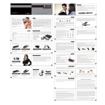
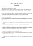
AV_CONTROL_V1_ENG.qxq
22/11/04
11:33 am
Page 1
JOYTECH
™
AV CONTROL CENTER 2
USER GUIDE
VERSION 1.0
AV_CONTROL_V1_ENG.qxq
22/11/04
11:33 am
Page 2
CONTENTS
ENGLISH
WELCOME
Thank you for purchasing the JOYTECH AV Control Center 2. Before connecting the AV
Control Center 2, please familiarize yourself thoroughly with this User Guide so that you
fully understand the setup procedure and functions of the product.
CONTENTS
CHECK THAT YOU HAVE THE FOLLOWING ITEMS:
1) AV Control Center 2
ENGLISH
. . . . . . . . . . 00 – 00
2) SCART Cable
3) S-Video / Audio Cable
DEUTSCH . . . . . . . . . . 00 – 00
4) Composite/ Audio Cable
5) Ethernet Cable
FRANÇAIS
. . . . . . . . . 00 – 00
6) AC Power Adapter
7) Remote Controller
SVENSKA
. . . . . . . . . 00 – 00
8) SCART Adapter
9) User Guide
HOLLANDS . . . . . . . . . 00 – 00
AV CONTROL CENTER LAYOUT
ITALIANO . . . . . . . . . . 00 – 00
FRONT VIEW
ESPAÑOL . . . . . . . . . . 00 – 00
Power/Standby
Input Channel Display
Input Selector
PORTUGUÊS . . . . . . . . 00 – 00
Display Settings Controls
2
Input 6
IR Remote Receiver
Power / Standby
Press to turn the AV Control Center 2 power On and Off.
The Power / Standby LED will illuminate green when the
power is on and red when the unit is in standby mode
Input Channel Display
Each Input Channel name can be programmed in order to
identify the AV device that is connected to each Input
Channel
3
AV_CONTROL_V1_ENG.qxq
22/11/04
11:33 am
Page 4
ENGLISH
ENGLISH
REMOTE CONTROLLER
Input Selector
Press to page through and select the required Input Channel
You can page through each Input Channel by pressing the Select Button on the front
IR Remote Receiver
For use with the Remote Controller
panel of the AV Control Center 2. Alternatively you can select each Input Channel by
Display Setting Controls These controls are used to program the Input Channel
names displayed on the LCD Display
Input 6
Primarily used for temporary connection of camcorders and
other AV devices to the AV Control Center 2
using the Directional or Numerical Buttons on the Remote Controller.
The Standby Button located on the Remote Controller allows the AV Control Center 2
to be switched from on to standby mode.
Standby
Directional
Buttons
REAR VIEW
Numerical
Buttons
AC 9V IN
Input 1
Input 2
Input 3
Input 4
Input 5
Output
When inserting new batteries into the Remote Controller take care to observe the
correct polarity.
The AV Control Center 2 has a total of 6 Input Channels. Input 6 is located on the front
panel and Inputs 1 to 5 are located on the rear panel. Each Input Channel comprises of
either 5 or 7 Input Connectors (figure.1)
CONTENTS
Requires 2 x AAA (LR03) alkaline batteries.
EXAMPLE OF A TYPICAL SETUP USING THE AV CONTROL CENTER 2
The AV Control Center 2 has been designed to connect up to 6 separate AV devices and
output the Audio/ Video signal to a single input on the TV / Hi-Fi. Each device can be
selected independently of each other. Once a device has been connected there is no
need to remove any of the cables when selecting an input. Figure 2 shows a typical AV
set up using the AV Control Center 2.
Figure 1.
Composite video (yellow)
Left Audio (white)
Right Audio (red)
S-Video
Optical Audio
Figure 2.
DVD Player
satellite receiver
VCR
Xbox™
PlayStation®2
TV
stereo Hi-Fi
camcorder
SCART
Ethernet
NOTE: The devices connected in this illustration are for reference only. Any suitable
device may be connected to the Input Channels.
4
5
AV_CONTROL_V1_ENG.qxq
22/11/04
11:33 am
Page 6
ENGLISH
ENGLISH
WHICH CABLE DO I USE?
SETUP INSTRUCTIONS
Depending on the type of output available from your AV device, use the most suitable
cable connection from the ‘Input Connection Table’ below:
1) Connect the AC Power Adapter to the AC 9V IN located on the rear panel of the AV
Control Center 2.
NOTE: The AV Control Center 2 is supplied with a standard Cable Pack. You may require
additional cables to set up your chosen AV devices.
2) Connect the desired output of the AV Control Center 2 to your television, using the
SCART, S-Video or RCA Phono Cable supplied.
OUTPUT FROM YOUR AV DEVICE
HOW TO CONNECT
Composite Video and Mono Audio:
Connect the yellow video RCA connector to a
yellow RCA Input Socket and the white audio RCA
connector to a white RCA Input Socket.
Alternatively you can connect the RCA leads to
the SCART Adapter and follow the instructions
for SCART connections.
Composite Video and Stereo Audio:
Connect the yellow video RCA connector to a
yellow Input RCA Socket, the white audio RCA
connector to a white RCA Input Socket and the
red audio RCA connector to a red RCA Input
Socket. Alternatively you can connect the RCA
leads to the SCART Adapter and follow the
instructions for SCART connections.
S-Video and Stereo Audio:
Connect the S-Video connector to a 4-pin DIN
Input Socket, the left audio connector to a white
RCA Input Socket and the right audio connector
to a red RCA Input Socket.
SCART:
Connect the SCART connector to a SCART Input
Socket. Note: SCART will normally carry both the
video and stereo audio signals. This is the most
versatile AV connection and is recommended
wherever possible.
Connect the SCART connector to a SCART Input
Socket and the digital optical connector to the
Digital Optical Socket in the same Input Channel.
SCART and Digital Optical:
Remember to remove the dust cap and store
safely for when Optical Socket is not in use.
Connect the Ethernet cable to an Ethernet Input
Socket.
Note: Your modem must either be a DSL or a
cable modem. Do not use the AV Control Center
2 with a standard telephone modem.
Ethernet:
IMPORTANT: Before connecting your modem to the AV
Control Center 2, make sure you have a valid account.
Connect a composite video and mono/ stereo
audio cable to the SCART Adapter and connect
to any SCART Input Socket.
SCART Adapter:
Note: If you are using the S-Video Cable as the video output, you will need to connect
the RCA Phono Cable (White and red) to the TV/Hi-Fi in order to receive audio. S-Video
connectors do not carry an audio signal.
3) Connect your AV devices to inputs 1 to 5 ensuring the power is switched off on all
devices before connecting.
4) Switch on your TV and select the “External” input channel. (Refer to your television
user guide for more details).
5) Switch on the AV Control Center 2 either by pressing the Power / Standby Button
on the front of the AV Control Center 2 or by using the Remote Controller. The Power
/ Standby LED will illuminate green when the unit is on.
6) The first Input Indicator to illuminate will be Input 1. You can select other Inputs by
pressing the SELECT Button located on the front of the AV Control Center 2 or by
using the Remote Controller.
PROGRAMMING THE INPUT CHANNEL DISPLAY
For easy identification of the AV equipment connected to the AV Control Center 2 it is
possible to name each of the 6 inputs on the Input Channel Display. For example should
you wish Input 1 to read ‘DVD’ and Input 2 to read ‘GAME’, follow this setup procedure:
1) Using the Select Button on the front panel, select the desired Input Channel (1-6)
that you would like to name.
2) Open the access cover on the front of the AV Control Center 2.
3) Press the SET Button to begin to change the name. The first character on the Input
Channel Display will begin to flash.
4) Use the + and - buttons to cycle through all the available characters. When the
desired character is displayed, press the SET Button to select the character and
move to the next. Repeat the process until you have achieved your desired name.
5) Once you have selected the 5th character the name will be stored and assigned to
your chosen Input Channel.
Repeat the above procedure for each Input Channel you wish to name.
IMPORTANT:
Each input connection will only correspond to the matching output connection except Input 6 (See
below). For example a SCART cable attached to SCART Input 1 can only be viewed via the SCART
Output Socket and cannot be displayed via the S-Video, Composite Video or Stereo Audio RCA
Output Sockets.
INPUT 6: The Composite Video and Stereo Audio RCA Input Sockets on Input 6 link directly to both
the corresponding Output Sockets and the SCART Output Socket located on the rear panel of the
unit. The S-Video Input Socket on Input 6 links directly to the S-Video Output Socket located on
the rear panel of the unit.
6
7
AV_CONTROL_V1_ENG.qxq
22/11/04
11:33 am
Page 8
ENGLISH
ENGLISH
TROUBLESHOOTING
CAUTION:
THE AV CONTROL CENTER 2 FAILS TO TURN ON:
• Do not remove this product when the console power is ON.
• Ensure that the AC Power Adapter is connected correctly and that the power is
switched on.
• Avoid placing this product near extreme temperatures or humidity.
• If the Power / Standby Button at the front of the AV Control Center 2 is red, then
the unit is in standby mode. Switch on by either pressing the Power / Standby
Button at the front of the AV Control Center 2 or by pressing the Standby Button
on the Remote Controller. The Power / Standby LED will illuminate green when the
power is ON.
• Do not submerse or allow this product to come into contact with water. Use in dry
locations only.
• An adult should supervise young children when using this product.
• Use of any attachment or accessory with this product not recommended or sold by
JOYTECH may result in risk of fire, electrical shock or injury to persons or product.
• Do not clean any parts with alcohol, cleaning solutions containing alcohol or strong
abrasives. Use a soft cloth and a little water
THE AV CONTROL CENTER 2 IS ON, BUT I DO NOT SEE A PICTURE FROM MY TV:
• Tampering with this product will invalidate your JOYTECH warranty.
• Ensure that the AV Control Center 2 is connected correctly to your television and
that the correct video input on your TV has been selected (Refer to your TV
instruction manual for more information).
IMPORTANT HEALTH WARNINGS
• Make sure each AV device is connected to the AV Control Center 2 correctly.
• Ensure you have selected the correct Input Channel on the AV Control Center 2.
THE AV CONTROL CENTER 2 IS ON, BUT THERE IS NO SOUND FROM MY TV:
• Check that the AV device is connected to the AV Control Center 2 using EITHER the
left and right Stereo Audio RCA Input Sockets, SCART or Digital Optical Inputs.
Photosensitive Seizure Warning
A very small percentage of people may experience a seizure when exposed to certain visual
images, including flashing lights or patterns that may appear in video games. Even people who
have no history of seizures or epilepsy may have an undiagnosed condition that can cause
these “photosensitive epileptic seizures” while watching video games.
These seizures may have a variety of symptoms, including lightheadedness, altered vision, eye
or face twitching, jerking or shaking of arms or legs, disorientation, confusion, or momentary
loss of awareness. Seizures may also cause loss of consciousness or convulsions that can
lead to injury from falling down or striking nearby objects.
• Make sure that the volume settings on your TV and AV devices are set correctly.
Remember that the S-Video connectors do not transmit an audio signal.
Immediately stop playing and consult a doctor if you experience any of these symptoms.
WHEN I VIEW A DEVICE I GET BACKGROUND INTERFERENCE
Taking the following precautions may reduce the risk of photosensitive epileptic seizures:
• Ensure that all AV devices that are connected to the AV Control Center 2 and not
being viewed are switched OFF as certain devices emit strong signals, which can
interfere with the AV device being viewed.
• Sit further away from the screen
Parents should watch for or ask their children about the above symptoms - children and
teenagers are more likely than adults to experience these seizures.
• Use a smaller TV screen
• Play in a well-lit room
• Check that the connections between AV devices are secure.
• Do not play when you are drowsy or fatigued
If you or any of your relatives have a history of seizures or epilepsy, consult a doctor before
playing.
BATTERY CARE
Incorrect use of batteries can result in battery leakage or explosion. When using
batteries, be sure to follow these instructions:
• Make sure that the plus and minus terminals of the batteries are inserted in the
correct directions.
• Do not mix old and new or different types of batteries.
• Do not attempt to recharge non-rechargeable type batteries.
• Remove the batteries when the product will not be used for an extended period of
time.
• If the battery has leaked, be sure to carefully remove all residue before inserting new
batteries.
8
We also advise you to take regular breaks of 15 minutes every hour.
HELPLINE
If you are experiencing a problem with this product contact the Joytech Product Helpline on
+44 (O) 8OO 38 99 647
(FREEPHONE UK ONLY)
or visit our website at www.joytech.net to obtain localised helpline numbers.
Design and specifications are subject to change without notice.
Dispose of this product or products contained in this pack in accordance with local and
national disposal regulations.
9