1
Catalog No:
Effective:
Replaces:
5000.64
3-1-04
NEW
4-20 mA / 2-10 VDC
Input Control Module
Used with
Y-200 Series Electronic Boiler Sequencer
& Outdoor Reset Control System
Installation and Operating Manual
P/N 241224
Installation and Operating Manual
4-20 mA / 2-10 VDC Input Control Module
Contents
Introduction
Introduction ............................................................... 1
The Raypak Y-200 Series Controller, equipped with
the 4-20 mA / 2-10 VDC Module, provides the ultimate in temperature setpoint control for Raypak
boiler applications.
Important Safety Instructions .................................... 1
Installation ................................................................. 2
Start-up ...................................................................... 3
Module Adjustment ................................................... 4
Limited Warranty ...................................................... 5
The 4-20 mA / 2-10 VDC Module provides a conversion, from either a milliamp or a voltage input from
an outside control source, to a setpoint temperature
reading on the Y-200 series controller LCD panel.
The Module is provided in a kit which includes the
necessary hardware to install the board onto the
Y-200 control board.
This manual should be used in conjunction with the
Y-200 Series Installation & Operating Manual (Catalog No. 5000.62, P/N 241125).
IMPORTANT SAFETY
INSTRUCTIONS
IMPORTANT NOTICE: These instructions are
intended for use by qualified personnel who are specifically trained and experienced in the installation of
this type of equipment and related system components. Some states may require that installation and
service personnel be licensed. Only qualified persons
shall attempt to repair this equipment. Repair must be
done according to the instructions provided.
WARNING: Improper installation, adjustment, alteration, service or maintenance may damage the
equipment, create a hazard resulting in asphyxiation,
explosion, fire, electric shock, personal injury or
property damage, and void the warranty.
CAUTION: This appliance has provisions to be connected to more than one (1) supply source. To reduce
the risk of electric shock, disconnect all connections
before servicing.
CAUTION: Risk of electric shock: more than one
(1) disconnect switch may be required to de-energize
the equipment before servicing.
1
4-20 mA / 2-10 VDC Input Control Module
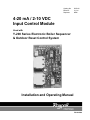
Installation
Installation and Operating Manual
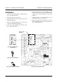
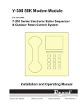
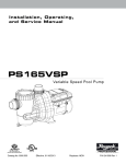
6.
Plug the 4-20 mA / 2-10 VDC Module into the
Y-200 Control Board at the J20 expansion port
(10-pin plug), securing Module with nylon
standoff.
1.
Verify that the control signal is within the 4-20
mA / 2-10 VDC parameter.
2.
Turn off the power to the Y-200.
7.
3.
Open the front cover of the Y-200 to access the
display/keypad door.
Attach 4-20 mA / 2-10 VDC signal wires to
2-pin plug connector (P/N 650935).
8.
Plug 2-pin connector into either the J1 or J2 connection of Module (J1 for 4-20 mA operation, J2
for 2-10 VDC operation).
4.
Open the display/keypad door to access the
Y-200 Control Board (P/N 601670).
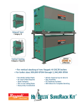
5.
Secure the nylon standoff (P/N 550767) onto
the Y-200 Control Board.
Hole for nylon
stand-off
4-20 mA /2-10 VDC Module
(P/N 601740)
Nylon stand-off (P/N 550767)
2-pin plug connector (P/N 650935)
2
Y-200 Control Board (P/N 601670)
Installation and Operating Manual
4-20 mA / 2-10 VDC Input Control Module
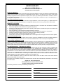
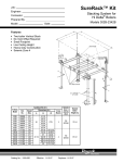
Start-up
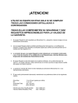
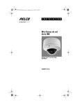
LED1
NOTE: The 4-20 mA / 2-10 VDC Module can be set
up for 4-20 mA mode or 2-10 VDC mode, not both.
4-20 mA Mode
1.
Restore power to the Y-200.
2.
Set the SW1-2 dip switch (4-20 mA) to the ON
position, and the SW1-1 dip switch (2-10 VDC)
to the OFF position.
3.
Green LED1 indicates Module is in 4-20 mA
mode.
4.
Green LED1 flashing once per second indicates a
weak (less than 4 mA) signal.
5.
Green LED1 flashing two times per second indicates an overload (over 20 mA) signal.
SW1
Module set to 4-20 mA mode
LED1
2-10 VDC Mode
1.
Restore power to the Y-200.
2.
Set the SW1-1 dip switch (2-10 VDC) to the ON
position, and the SW1-2 dip switch (4-20 mA) to
the OFF position.
3.
Red LED1 indicates Module is in 2-10 VDC
mode.
4.
Red LED1 flashing once per second indicates a
weak (less than 2 VDC) signal.
5.
Red LED1 flashing two times per second indicates an overload (over 10 VDC) signal.
Pin
SW1
Module set to 2-10 VDC mode
Interface Pin Functions
1
5 VDC
2
4-20 VDC selector switch
3
2-10 mA selector switch
4
4-20 VDC LED drive
5
N/C
6
N/C
7
2-10 mA output
8
4-20 VDC output
9
2-10 mA LED drive
10
GND
Pin 10
Pin 1
3
4-20 mA / 2-10 VDC Input Control Module
Installation and Operating Manual
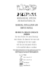
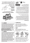
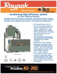
Module Adjustment
NOTE: The instructions below use a 140 °F setpoint
temperature.
POT1
4-20 mA Module
1.
Set the input device signal to 12 mA.
2.
Remove 2-pin connector from J1 connector on
Module.
3.
Verify 12 mA input signal at 2-pin plug connector using a calibrated digital volt meter (DVM).
4.
Plug 2-pin connector back into the J1 connector.
5.
Set Y-200 display to screen #2. (Refer to Y-200
Installation & Operating Manual, Catalog No.
5000.62.)
6.
If necessary, adjust POT1 to achieve a 140 °F
setpoint temperature on Y-200 display. (POT1:
Clockwise adjustment increases temperature;
counter-clockwise adjustment decreases temperature.)
2-10 VDC Module
POT2
Input vs. Setpoint Temperature
mA
Input
Volt
Input
Setpoint
Temp. (°F)
4
2
60
5
2.5
70
1.
Set the input device signal to 6 VDC.
6
3
80
2.
Remove 2-pin connector from J2 connector on
Module.
7
3.5
90
8
4
100
3.
Verify 6 VDC input signal at 2-pin connector
using a calibrated digital volt meter (DVM).
9
4.5
110
4.
Plug 2-pin connector back into the J2 connector.
10
5
120
5.
Set Y-200 display to screen #2. (Refer to Y-200
Installation & Operating Manual, Catalog No.
5000.62.)
11
5.5
130
12
6
140
13
6.5
150
14
7
160
15
7.5
170
16
8
180
17
8.5
190
18
9
200
19
9.5
210
20
10
220
6.
4
If necessary, adjust POT2 to achieve a 140 °F
setpoint temperature on Y-200 display. (POT2:
Counterclockwise adjustment increases temperature; clockwise adjustment decreases temperature.)
LIMITED WARRANTY
4-20 mA / 2-10 VDC Module
for Y-200 Series Electronic Boiler Sequencer
& Outdoor Reset Control System
SCOPE OF WARRANTY
Raypak, Inc. ("Raypak") warrants to the original owner the Control System to be free from defects in materials and workmanship under normal use and service for the applicable warranty period. In accordance with the terms of this Limited
Warranty, Raypak will furnish a replacement or repair, at our option, any defective part which fails in normal use and service during the applicable warranty period. The replacement or repair will be warranted for only the unexpired portion of
the original Warranty Period.
APPLICABLE WARRANTY PERIOD
The effective date of warranty coverage is the date of original installation, of the Control System, by a qualified electrician
or by a Raypak authorized service technician. The Applicable Warranty Period is one (1) year from the effective date.
WARRANTY EXCLUSIONS
This Limited Warranty does not apply:
1. if the control system is not properly installed by a qualified technician in accordance with manufacture's installation
instructions, applicable codes, ordinances and good trade practices,
2. to damage or malfunctions resulting from failure to properly install, operate or maintain the system in accordance with
the manufacture's instructions;
3. if the rating plate(s) or serial number(s) are altered, defaced or removed;
4. if the System is modified in any way or used with any non-factory authorized accessories or components;
5. to damage or failure from abuse, accident, act of nature, fire, flood, freezing or the like;
6. to accessories, rubber or plastic parts, light bulbs or glass parts;
7. if the System is moved from its original installation site; or if the original owner no longer owns the site or the System.
LABOR AND SHIPPING COSTS
This Limited Warranty does not cover labor costs for service, removal or reinstallation of any part nor shipping charges to
or from a Raypak designated repair center or to or from the installation site. All such costs are your responsibility.
HOW TO MAKE A WARRANTY CLAIM
To make a warranty claim, promptly ship (postage prepaid) or carry the defective part to a designated Raypak Service
Dealer or Service Station in the United States, supplying proof of purchase and date of installation and the model and
serial numbers. If you cannot locate a dealer, contact the Raypak Service Department at the address/telephone listed
below. Raypak reserves the right at all times to inspect the claimed defect and verify warranty coverage at its factory.
EXCLUSIVE WARRANTY - LIMITATION OF LIABILITY
This is the only warranty given by Raypak. No one is authorized to make any other warranties on behalf of Raypak. ANY
IMPLIED WARRANTIES, INCLUDING MERCHANTABILITY OR FITNESS FOR A PARTICULAR PURPOSE, SHALL
NOT EXTEND BEYOND THE APPLICABLE WARRANTY PERIOD SPECIFIED ABOVE. RAYPAK'S SOLE LIABILITY
WITH RESPECT TO ANY DEFECT SHALL BE AS SET FORTH IN THIS LIMITED WARRANTY. ANY CLAIMS FOR INCIDENTAL OR CONSEQUENTIAL DAMAGES (INCLUDING DAMAGE FROM WATER LEAKAGE) ARE EXCLUDED.
Some states do not allow limitations on how long an implied warranty lasts, or for the exclusion of incidental or consequential damages, so the above limitation or exclusion may not apply to you.
THIS LIMITED WARRANTY GIVES YOU SPECIFIC LEGAL RIGHTS, AND YOU MAY ALSO HAVE OTHER RIGHTS
WHICH VARY FROM STATE TO STATE.
We suggest you immediately complete the information below and retain this Limited Warranty Certificate in case warranty
service is needed.
Raypak, Inc., Service Department
2151 Eastman Avenue, Oxnard, California 93030
Telephone: (805) 278-5300 Fax (805) 278-5468
The following information must be provided when you write or call:
Original Owner
Model Number
Mailing Address
Serial Number
Date of Installation
City
Daytime Telephone Number
State
Zip Code
Installation Site
Contractor/Installer
www.raypak.com
Raypak, Inc., 2151 Eastman Avenue, Oxnard, CA 93030 (805) 278-5300 Fax (805) 278-5468
Raypak Canada Limited, 2805 Slough St., Mississauga, Ontario, Canada L4T 1G2 (905) 677-7999 Fax
(905) 677-8036
Litho in U.S.A.