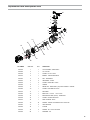
1
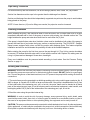
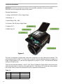
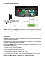
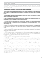
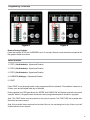
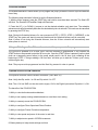
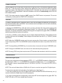
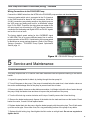
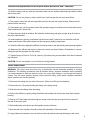
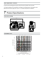
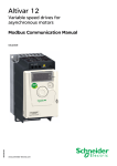
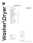
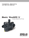
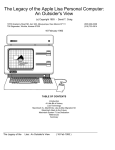
Installation, Operating,
and Service Manual
PS165VSP
Variable Speed Pool Pump
LISTED 31B4
Catalog No. 6000.555
Effective. 01/16/2013
Replaces: NEW
P/N 241508 Rev 1
Technical Support
Address: 7920 Interstate Court
North Ft. Myers, FL. 33917
Toll Free: 1-877-213-3726
Website: www.raypak.com
Manufactured for Raypak by Speck Pumps, Jacksonville Florida USA, © 2012-2013 All Rights Reserved.
This document is subject to change without notice.
Date of Installation:
Installed by:
Serial Number:
For Service Call:
Safety
Safety is emphasized throughout the user manual. These are safety alert symbols. They alert the user to
potential personal injury hazards. Obey all safety messages to avoid possible injury or death or damage
to equipment.
CAUTION
WARNING
DANGER
SAVE THESE INSTRUCTIONS!
2999999292 - Rev 01/2013 v1
Table of Contents
1
Important Safety Instructions
4
2
General Description
6
3
Installation Information
Preparation Guide . .
Pump Location . . .
Pipe Sizing . . . . .
Plumbing Installation .
Bonding and Grounding
Electrical Installation .
Pressure Testing . . .
4
.
.
.
.
.
.
.
.
.
.
.
.
.
.
.
.
.
.
.
.
.
.
.
.
.
.
.
.
.
.
.
.
.
.
.
.
.
.
.
.
.
.
.
.
.
.
.
.
.
.
.
.
.
.
.
.
.
.
.
.
.
.
.
Operation
Start-Up Guide . . . . . . . . . . . .
Energy Savings Optimization . . . . . . .
Programming . . . . . . . . . . . . .
Menu Structure . . . . . . . . . . . .
Keypad Lock . . . . . . . . . . . . .
Motor Pause . . . . . . . . . . . . .
Power Outage . . . . . . . . . . . . .
Schedule Advance . . . . . . . . . . .
Using an existing or new 24 hour timer . . .
Optional PS165VSP-RM Controller . . . .
Freeze Protection . . . . . . . . . . .
Override . . . . . . . . . . . . . . .
Communication . . . . . . . . . . . .
3rd Party Controllers (Wiring) . . . . . . .
Heat Pump Pool Heater Connections (Wiring)
.
.
.
.
.
.
.
.
.
.
.
.
.
.
.
.
.
.
.
.
.
.
.
.
.
.
.
.
.
.
.
.
.
.
.
.
.
.
.
.
.
.
.
.
.
.
.
.
.
.
.
.
.
.
.
.
.
.
.
.
.
.
.
.
.
.
.
.
.
.
.
.
.
7
7
8
8
9
9
10
11
.
.
.
.
.
.
.
.
.
.
.
.
.
.
.
12
12
13
14
15
16
16
16
17
17
17
18
18
18
20
24
5
Service and Maintenance
27
Routine Maintenance . . . . . . . . . . . . . . 27
Winterizing . . . . . . . . . . . . . . . . . . 28
6
Troubleshooting
Fault LED . . . . . . . . . . . . .
General Troubleshooting Problems . . .
Blocked Impeller . . . . . . . . . . .
Removal and Replacement of the Impeller
Motor Replacement
7
.
.
.
.
.
.
.
.
.
.
.
.
.
.
.
.
.
.
.
.
28
28
29
29
30
. . . . . . . . . . . . . . 31
Product Specifications
32
Performance Curve & Dimensional Drawing . . . . . 32
Replacement Parts and Exploded View . . . . . . . 33
1 Important Safety Instructions
READ THIS MANUAL CAREFULLY BEFORE USING THE PUMP
READ AND FOLLOW ALL INSTRUCTIONS!
Important Notice:
This manual contains important information about the installation, operation and safe use of this product.
This information should be given to the owner and/or operator of this equipment.
WARNING: This product must be installed and serviced by a qualified pool professional, and must
conform to all national, state, and local codes.
WARNING: Before Installing this product, read and follow all warning notices and instructions which are
included. Failure to follow safety warnings and instructions can result in severe injury, death, or property
damage. Call 1-877-213-3726 or visit www.raypak.com for additional copies of these instructions.
WARNING: California Proposition 65: This product contains chemicals known to the state of California to
cause cancer, birth defects or other reproductive harm.
WARNING - Entrapment Prevention
DANGER: DO NOT BLOCK SUCTION
SUCTION HAZARD. Can cause serious injury or death. Do not use
this pump for wading pools, shallow pools, or spas containing bottom
drains, unless pump is connected to at least two (2) functioning suction
outlets.
WARNING: Pump suction is hazardous and can trap and drown
or disembowel bathers. Do not use or operate swimming pools,
spas, or hot tubs if a suction outlet cover is missing, broken, or
loose.
The following guidelines provide information for pump installation
that minimizes risk of injury to users of pools, spas, and hot tubs:
Entrapment Protection: The pump suction system must provide
protection against the hazards of suction entrapment.
Suction Outlet Covers: All suction outlets must have correctly installed,
screw-fastened covers in place. All suction outlet (drain) covers must be
maintained. Drain covers must be listed/certified to the latest published
edition of ANSI/ASME A112.19.8 (ANSI/APSP-16, 2011). They must be
replaced if cracked, broken, or missing.
Number of Suction Outlets Per Pump: Provide at least two (2)
hydraulically-balanced main drains, with covers, as suction for each
circulating pump suction line. The centers of the main drains (suction
outlets) on any one (1) suction line must be at least three (3) feet apart,
center to center.
4
WARNING - Entrapment Prevention - continued
The system must be built to include at least two (2) suction outlets (drains) connected to the pump
whenever the pump is running. However, if two (2) main drains run into a single suction line, the single
suction line may be equipped with a valve that will shut off both main drains from the pump. The system
shall be constructed such that it shall not allow for separate or independent shutoff or isolation of each
drain.
More than one (1) pump can be connected to a single suction line as long as the requirements above are
met.
Water Velocity: The maximum water velocity through the suction fitting or cover for any suction outlet
must be 1.5 feet per second, unless the outlet complies with the latest published edition of ANSI/ASME
A112.19.8 (ANSI/APSP-16, 2011), the standard for Suction Fittings For Use in Swimming and Wading
Pools, Spas, Hot Tubs, and Whirlpool Bathtub Applications. In any case, do not exceed the suction
fitting’s maximum designed flow rate.
If 100% of the pump’s flow comes from the main drain system, the maximum water velocity in the pump
suction hydraulic system must be six (6) feet per second or less, even if one (1) main drain (suction
outlet) is completely blocked. The flow through the remaining main drain(s) must comply with the latest
published edition of ANSI/ASME A112.19.8 (ANSI/APSP-16, 2011), the standard for Suction Fittings For
Use in Swimming and Wading Pools, Spas, Hot Tubs, and Whirlpool Bathtub Applications.
Testing and Certification: Suction outlet covers must have been tested by a nationally recognized
testing laboratory and found to comply with the latest published edition of ANSI/ASME A112.19.8 (ANSI/
APSP-16, 2011), the standard for Suction Fittings For Use in Swimming and Wading Pools, Spas, Hot
Tubs, and Whirlpool Bathtub Applications.
Fittings: Fittings restrict flow; for best efficiency use fewest possible fittings (but at least two (2) suction
outlets).
Avoid fittings that could cause an air trap.
Pool cleaner suction fittings must conform to applicable International Association of Plumbing and
Mechanical Officials (IAPMO) standards.
WARNING - Risk of Electrical Shock or Electrocution
This pool pump must be installed by a licensed or certified electrician or
a qualified pool serviceman in accordance with the National Electrical
Code and all applicable local codes and ordinances. Improper installation
will create an electric hazard which could result in death or serious injury
to pool users, installers, or others due to electrical shock, and may also
cause damage to property.
Always disconnect power to the pool pump at the circuit breaker
before servicing the pump. Failure to do so could result in death or
serious injury to serviceman, pool users, or others due to electric shock.
5
Important Safety Instructions
When installing and using this electrical equipment, basic safety precautions should always be
followed, including the following:
READ AND FOLLOW ALL INSTRUCTIONS
WARNING: To reduce the risk of injury, do not permit children to use this product unless they are closely
supervised at all times.
WARNING: Risk of Electrical Shock. Connect only to a grounding type receptacle protected by a groundfault circuit-interrupter (GFCI). Contact a qualified electrician if you cannot verify that the receptacle is
protected by a GFCI.
The unit must be connected only to a supply circuit that is protected by a ground-fault circuit-interrupter
(GFCI). Such a GFCI should be provided by the installer and should be tested on a routine basis. To test
the GFCI, push the test button. The GFCI should interrupt power. Push the reset button. Power should be
restored. If the GFCI fails to operate in this manner, the GFCI is defective. If the GFCI interrupts power to
the pump without the test button being pushed, a ground current is flowing, indicating the possibility of an
electric shock. Do not use this pump. Disconnect the pump and have the problem corrected by a qualified
service representative before using.
CAUTION: This pump is for use with permanently installed pools and may also be used with hot tubs
and spas if so marked. Do not use with storable pools. A permanently installed pool is constructed in or
on the ground or in a building such that it cannot be readily disassembled for storage. A storable pool is
constructed so that it may be readily disassembled for storage and reassembled to its original integrity.
TO REDUCE THE RISK OF ELECTRICAL SHOCK, connect ground wires to grounding screw located in
the motor. Use no smaller than a #12 AWG (3.3mm2) wire.
TO REDUCE THE RISK OF ELECTRICAL SHOCK, a bonding connector is provided for bonding to
metal water pipes, metal rails, or other metal within 5 feet of the swimming pool. All local points should be
bonded with a #8 AWG (8.4mm2) wire.
SAVE THESE INSTRUCTIONS.
2 General Description
Raypak Professional PS165VSP - Variable Speed
The PS165VSP - Variable Speed swimming pool pump is both environment friendly and cost efficient.
This Premium Efficiency Variable Speed Pump provides tremendous flexibility in motor speed and time
settings. The integrated electronic interface controls the speed settings between 600 and 3450 rpm
and the start and stop times. It is designed to maximize energy conservation, optimize chemical usage,
and yet still be simplistic to use. The PS165VSP is intended to run on the lowest speeds needed to
maintain a healthy pool environment, which in turn translates into money savings. With speed settings
of 3450, 3100, 2850, 2600, 2350, 2100, 1850, 1600, 1350, 1100, 850, 600, and 0, it easily allows you to
choose the most appropriate speed for the maximum savings. With pump parts made of 100% recyclable
plastic and engineering designed to significantly reduce greenhouse emissions, it is sure to please the
environmentally minded consumer.
6
General Description - continued
Figure 1
The PS165VSP - Variable Speed control panel provides manual speed controls for the pump.
Controls and LEDs
LED Lights (Active Step LEDs)
Speed LED
Duration LED
Bar Graph
Programming Buttons
Power LED
Description
When lit, indicates it is in operation or active.
When lit, Bar Graph displays speed.
When lit, Bar Graph displays duration in hours speed will run.
Shows current speed and duration (hours) of active programmed button
or selected value during programming.
Four programmable buttons, to be set for speed and length of time.
Indicates unit has power.
Fault LED
Indicates the unit has a fault error.
+/- Buttons
Increases or decreases speed or duration of selected value.
STOP button
Stops pump and programming.
START button
Must be pressed to start the pump and programming.
3 Installation Information
Preparation Guide
1. Upon receipt of the pump, check the carton for damage. Open the carton and check the pump for
concealed damage, such as cracks, dents, or a broken base. If damage is found, contact the shipper or
distributor where the pump was purchased.
2. Inspect the contents of the carton and verify that all parts are included. See Section 7, Parts List and
Exploded View for details.
7
Pump Location
WARNING: This product must be installed and serviced by a qualified pool professional, and must
conform to all national, state, and local codes. Before installing this product, read and follow all warning
notices and instructions of this product. Failure to follow warning notices and instructions may result in
property damage, personal injury, or death.
ATTENTION INSTALLERS: This manual contains important information about the installation, operation,
and safe use of this product. This manual should be given to the owner/operator of this equipment.
1. Raypak recommends in order to achieve better priming, to install the pump as close to the pool as
practical and run suction lines as direct as possible to reduce friction loss.
2. It is recommended that a minimum length of straight pipe, equivalent to five (5) times the pipe diameter
be used between the pump suction inlet and any plumbing fittings (elbows, valves, etc.).
3. Install the pump on a level, solid foundation which provides a rigid and vibration-free base. Secure the
pump to the base with screws or bolts to further reduce vibrations and stress on the plumbing.
4. Protect the pump against flooding and excess moisture. Select an area that will not flood when it rains.
DO NOT install the pump in a damp or non-ventilated location.
5. Keep the motor clean and provide free circulation of air for cooling.
6. Although the pump is designed for outdoor use, it is recommended to protect the pump from direct
sunlight and excessive moisture (rain, sprinklers, etc.).
7. DO NOT store or use gasoline or other flammable vapors or liquids in the vicinity of this pump. DO NOT
store pool chemicals near the pump.
8. DO NOT remove any safety alert labels such as DANGER, WARNING, or CAUTION. Keep safety
labels in good condition and replace any missing or damaged labels.
9. Provide access for future services by leaving a clear area around the pump. Allow plenty of space
above the pump to remove lid and basket for cleaning.
WARNING: Some Safety Vacuum Release System (SVRS) devices are not compatible with the installation
of check valves. If the pool has an SVRS device, be sure to confirm that it will continue to safely operate
when the check valves are installed.
NOTE: In Canada, the pump must be located a minimum of three (3) meters (approximately ten (10) feet)
from the water (CSA C22.1).
Pipe Sizing
NOTE: All pipe sizes are able to withstand the pressures the pump will deliver, but not necessarily the
flow. If the pipe is too small for the pump, or is elevated above water, the maximum gallons per minute
(GPM) may not be delivered. If this happens, the pump will develop a pocket of air (cavitation) that makes
noise. This may shorten the life of the pump.
SUCTION & DISCHARGE:
When the pump is located up to fifty (50) feet from the pool, the recommended minimum pipe size for both
the suction and discharge is 2”.
8
Pipe Sizing - continued
For better efficiency and less restriction, use as few fittings (elbows, tees, valves, etc.) as possible.
Suction line diameter must be equal or be greater than the discharge line diameter.
Suction and discharge lines should be independently supported at a point near the pump to avoid strains
being placed on the pump.
NOTE: If more than ten (10) suction fittings are needed, the pipe size must be increased.
Plumbing Installation
When installing the pump, care should be taken to see the suction line is below water level to a point
immediately beneath and in front of the pump to ensure quick priming via a flooded suction line. The
height between the pump and water level should not be more than five (5) feet.
If the pump is located below water level, isolation valves must be installed on both sides of the pump to
prevent the back flow of pool water during any routine or required servicing. The PS165VSP - Variable
Speed comes equipped with unions on both the suction and discharge ports. This feature simplifies
installation and service and eliminates the possibility of leaks at the threaded adaptors.
Before starting the pump for the first time, remove the see-through lid. (Turn lid ring counter clockwise
to remove.) Fill strainer tank with water until it is level with the suction inlet. Replace lid, making sure the
o-ring is in place and not damaged. Screw down, hand tight.
Every new installation must be pressure tested according to local codes. See the Pressure Testing
Section on page 11.
Bonding and Grounding
WARNING: Ground and bond the pump before connecting to electrical power supply. Failure to ground
and bond the pump can cause serious or fatal electrical shock hazard. DO NOT ground to a gas supply
line. To avoid dangerous or fatal electrical shock, turn OFF power to the pump before working on electrical
connections.
1. The motor frame must be grounded to a reliable grounding point using a solid copper conductor, No. 8
AWG or larger. In Canada, No. 6 AWG or larger must be used. If the pump is installed within five (5) feet
of the inside walls of the swimming pool, spa, or hot tub, the motor frame must be bonded to all metal
parts of the swimming pool, spa, or hot tub structure and to all electrical equipment, metal conduit, and
metal piping within five (5) feet of the inside walls of the swimming pool, spa, or hot tub.
2. Bond the motor using the provided external lug.
WARNING: In order to avoid the risk of property damage, severe personal injury, and/or death, make
sure that the control switch, time clock, or control system is installed in an accessible location, so that in
the event of an equipment failure or loose plumbing fitting, the equipment can be easily turned off.
CAUTION: The pump must be permanently connected to a dedicated electrical circuit. No other equipment,
lights, appliances, or outlets may be connected to the pump circuit, with the exception of devices that may
be required to operate simultaneously with the pump, such as a chlorinating device or heater.
9
Electrical Installation
WARNING: All electrical wiring must conform to the local NEC guidelines. A licensed, qualified
electrician should complete the wiring for this product.
Electrical Specifications
1. Voltage: 208-230 VAC, 60 Hz, Single Phase
2. Max Amps: 11
3. Speed Range: 600 - 3450
4. Controller: 208-230 Vrms, Single Phase
o
5. Ambient: 50 C
6. NEMA Type 3R
Figure 2
The motor is designed to handle either a bare wire connection or a quick disconnect connection. The
quick disconnect tab is 0.250”. For a direct wire connection, the wire insulation should be stripped to a
length of approximately 0.33” and the screw tightened to a torque of 10 in-lb. The terminals will handle
wire up to 12 AWG in size.
There are two terminals labeled L1 and L2. (See Figure 3) Attach the power leads to these terminals.
Attach the black lead to L1 and the red or white lead to L2. (See Table 1.0) The top rear of the controller
has a single screw. Loosen this screw and lift cover to expose the terminal area.
Table 1.0
Pin#
Wire Color
Description
L1
Black
Hot 1
L2
Red or White
Hot 2
Green
Ground
GRD
10
Electrical Installation - continued
On
Off
12345
Note: All Dip switches should be in the
OFF position when external controllers
are not being used.
Figure 3
CAUTION: Voltage at the pump MUST NOT vary by more than +/- 10% of nameplate voltage. Components
may overheat, causing overload tripping and reduced component life. Consult your power company if this
condition exists.
Note: Use only liquid tight fittings to protect the electronics and motor.
Pressure Test
WARNING: To minimize the risk of severe injury or death, the filter and/or pump should not be subjected
to the piping system pressurization test.
Local codes may require the pool piping system to be subjected to a pressure test. These requirements
are generally not intended to apply to the pool equipment.
However, if the WARNING cannot be followed and pressure testing of the complete system must be
done, follow the following guidelines:
1. RELEASE ALL AIR in the system before testing.
2. Water pressure for the test must NOT EXCEED 35 PSI.
3. Water temperature for the test must NOT EXCEED 100° F (38° C).
4. Limit the test to 24 hours. After the test, visually check the system to be sure it is ready for operation.
DO NOT USE COMPRESSED AIR TO PRESSURE TEST OR CHECK FOR LEAKS.
11
4 Operation
Start Up Guide
CAUTION: Never run the pump without water. Running the pump “dry“ for any length of time can cause
severe damage to both the pump and the motor and will void the warranty.
If this is a new pool installation, make sure all piping is clear of construction debris and has been properly
pressure tested. The filter should be checked for proper installation, verifying that all connections and
clamps are secure according to the manufacturer’s recommendations.
WARNING: To avoid risk of property damage, severe personal injury or death, verify that all power is
turned off before starting this procedure.
1. Depending on the location of the pump, do one of the following:
If the pump is located below the water level of the pool, open the filter pressure valve to prime the pump with water. Once all the air has left the filter, close the filter pressure release valve.
If the pump is located above the water level of the pool, remove the lid and fill the basket with water
before starting the pump.
2. Prior to replacing the lid, check for debris around the lid o-ring seat. Debris around the lid o-ring seat
will make it difficult to prime the pump.
3. Hand-tighten the lid to make an air tight seal. Do not use any tools to tighten the lid: hand-tighten
only. Make sure all valves are open and the unions are tight.
4. Restore power to the system.
5. Pressing the START key will start the motor based on the factory default schedule. (See Table 2.0)
Table 2.0 - Factory Default Schedule
Button
Speed (RPM)
Duration (Hours)
STEP 1
1100
12
STEP 2
0
0
0
0
3450
2
STEP 3
OVERRIDE
Note: Motor will always run the PRIMING sequence when starting from 0 speed, Stop position, or OFF
power. The factory priming settings are 3450 RPM for 3 minutes.
6. (Self Priming Pump) Open the filter pressure relief valve until all air has escaped and then close.
7. If the pump does not prime and all instructions to this point have been followed, check for a suction
leak. Repeat steps 2-7.
8. For technical assistance, call Technical Support at 1-877-213-3726.
12
Start Up Guide - continued
NOTE: If power goes off to the motor and the user did not press the STOP key, then the motor will
automatically start and run the programmed schedule. This will ensure that the motor will re-start in the
case of a power outage.
Energy Savings Operation - PS165VSP Pump Speed Optimization
The PS165VSP pumps come with factory defaults of STEP 1 set for 1100 RPM for 12 hours duration and
the OVERRIDE set for 3450 RPM for 2 hours duration. The remainder of the 24 hour day, the pump will
be OFF.
These speeds and durations can be programmed on site for each specific pool installation to support
specific pool parameters and equipment.
In order to maximize Energy Savings from pump operation, follow the steps below to optimize the pool
pump speeds to take full advantage of these savings opportunities.
1. Push the OVERRIDE button directly from the pump control, adjust the pump speed to determine the
proper operation rpm of the pump for each device intended for use on the pool (filter, vacuum, HPPH,
gas pool heater, etc.).
2. Use the UP (+) or DOWN (-) buttons on the pump control to increase/decrease the pump speed while
in the OVERRIDE mode (NOTE: The light over the OVERRIDE button will be lit when in OVERRIDE
mode).
3. Record the lowest RPM that allows each pool device to work properly and save for future reference
and use later in these instructions.
4. STEP 1 is primarily used to circulate the pump for a sufficient period each day to ensure proper turn
over of the pool water and filtration. Adjust the pump speed and duration for STEP 1 as determined for
proper operation of the filtration system (proper number of turns per day).
5. STEP 2 and STEP 3 can be used and set for other equipment operation.
6. OVERRIDE is used by the HPPH for heater operation. Adjust the flow rate so that it is just sufficient
for the unit to operate. This is the lowest setting for heat pump operation and will result in the greatest
energy savings.
7. OVERRIDE may also be used for other pool service tasks. If it is adjusted for any other purpose,
please remember to readjust when completed to the preset value as the HPPH uses this RPM for proper
heating/cooling operation.
8. Once all pump speeds have been determined, you can adjust the programs in the pump accordingly,
See the Programming Section on page 14.
NOTE: It is best to use a speed slightly above the minimum speed determined in the steps above to
ensure proper operation under dirty filter or clogged strainer baskets, etc. Example, if the heater operation
requires a setting of 1600 RPM – use 1850 RPM. This still maximizes pump energy cost savings, but
also reduces the probability of nuisance issues with the pool equipment not operating properly because
of insufficient water flow.
13
Programming
Operates on a 24 hour cycle that begins from the time the START button is pushed. To start the cycle at
a specific time, See the Schedule Advance Section on page 17.
Programmable Speed Settings:
3450, 3100, 2850, 2600, 2350, 2100, 1850, 1600, 1350, 1100, 850, 600, 0
NOTE: 0 is a programmable speed (RPM) and can be set for a specific duration.
Programmable Duration Settings (Hours)
24, 22, 20, 18, 16, 14, 12, 10, 8, 6, 4, 2, 0
Note: Up to three separate speeds with duration may be set. The sum of the three durations combined
must not exceed 24 hours. If the three combined exceed 24 hours, the pump will keep the current step
and re-write the remaining two steps to zero.
User can change the program duration and speed of STEP 1, STEP 2, STEP 3 & OVERRIDE keys.
Note: Pump must be OFF for programming speed and duration of the STEP 1, 2, 3 keys. Override speed
and duration can be programmed when the motor is either OFF or running.
Four programmable buttons lay across the top of the Keypad (overlay). (See Figure 4 - shows the speed
being set at 3100 RPM.) The LED directly above each button when lit indicates it is in operation or active.
To create a custom schedule and change the factory defaults settings, follow these steps:
1. Place the pump in the stop position (Press STOP Button).
2. Press the STEP 1 button. The LED above it will illuminate. The LED above the SPEED column will
illuminate.
3. Using the UP (+) or DOWN (-) arrows, toggle to the desired speed. The Bar graph will show the setting
as you toggle up and down. (See Figure 4 - shows the speed being set at 3100 RPM.)
4. Press the STEP 1 button again. The LED above the duration column will be lit.
5. Using the UP (+) or DOWN (-) arrows, toggle to the desired duration that you want this speed to run in
hours. The Bar graph will show the setting as you toggle up and down. (See Figure 5 - shows the duration
being set at 10 hours.)
6. Press any of the other STEP or the OVERRIDE button to save these settings for STEP 1.
7. To exit the system and not save these settings, press the STOP button.
8. Press STEP 2, STEP 3, or OVERRIDE key. Repeat steps 3-6 to program the corresponding speed and
duration for each button.
14
Programming - continued
Figure 4
Figure 5
Restore Factory Defaults:
Press and hold the STOP and OVERRIDE key for 3 seconds. When the reset has been recognized the
Bar graph will blink three times.
Menu Structure
1. STEP 1 (Set Schedule) a. Speed and Duration
2. STEP 2 (Set Schedule) a. Speed and Duration
3. STEP 3 (Set Schedule) a. Speed and Duration
4. OVERRIDE (Settings) a. Speed and Duration
5. START
Press START to run the pump based on the programmed 24 hour schedule. The schedule is based on a
24 hour cycle and will repeat each day of the week.
During operation the LED lights above the “SPEED” and “DURATION” will flip back and forth every three
seconds. When lit, the graph below will show the active programmed speed or duration in progress.
Note: The START button must be pressed for the pump to operate. The START LED will illuminate after
the button has been pressed.
Note: If the schedule times combined are less than 24 hours, the remaining time for the 24 hour cycle will
be filled with the motor stopped.
15
Menu Structure - continued
Schedule Table
Use these tables to enter a personalized operating schedule. By writing down the planned schedule, it
will make the programming process easier and will help the user to remember the user’s settings in case
the programming is inadvertently lost. The User Interface will not allow the user to program an overlap
between different steps of the schedule. The STEP currently being set will always take priority of any
older settings. Therefore, the duration for the other two (2) STEPs not currently being set will be cleared
to 0 hours and have to be programmed again by the user. It is always a good idea to double check your
programmed settings once you have completed the programming process.
Setup #1
STEP 1
STEP 2
STEP 3
OVERRIDE
Speed (RPM)
Duration (Hours)
Keypad Lock
The Keypad has a “key lockout” feature to prevent
unwanted changes to the settings. To lock the keys,
hold down the STEP 1, 2, and 3 buttons all at the
same time for more than 3 seconds. The “active step
LEDs” for STEP 1, 2 and 3 will blink for 30 seconds
indicating that the keypad is locked. (See Figure 6)
The user can unlock the keys by holding down the
same buttons for more than 3 seconds. The “active
step LEDs” for STEP 1, 2 and 3 will illuminate
continuously indicating the keypad is unlocked.
Figure 6
Motor Pause
Allows for temporary turn off of the motor.
1. Press and hold the START button for three seconds while the motor is running. The motor will turn off
and the START and OVERRIDE LED’s will blink.
2. To resume running, hold the START button for three seconds.
Power Outage
If there is a power outage and the user does not press the STOP key, upon power being restored,
the pump will automatically start and run the schedule starting with STEP 1. This feature ensures that
the motor will re-start in the event of a power outage. The Priming sequence precedes STEP 1. All
programming is retained.
16
Schedule Advance
The Schedule Advance Feature allows you to program the pump yet start the 24 hour cycle at a different
time of day.
The following steps should be followed to set the Schedule Advance:
1. With the motor stopped, press the START Key and hold for more than three seconds. The Start LED
will blink. The Duration LED and Bar Graph will illuminate.
2. Press the UP (+) or DOWN (-) arrows to set the desired schedule cycle start time. The schedule
advance mode will automatically start after the desired delay time is selected. This mode can be cancelled
by pressing the STOP key.
Note: During the Schedule Advance if a user presses the STEP 1, STEP 2, STEP 3, OVERRIDE, or the
START key, the system will start the normal schedule and the Schedule Advance will be cancelled.
Note: If power is lost during the Schedule Advance, then the 24 hour schedule will automatically start
when power is restored.
Using an Existing or New 24 hour timer to start the pump controller program
The PS165VSP operates on a 24 hour cycle. Once the controller is programmed, it only requires the
START button to be pressed to start the 24 hour cycle. Once the START button is pressed, power cycled
(such as a temporary power failure) to the pump would result in the 24 hour cycle restarting at the
beginning of STEP 1. Using or adding a “24 hour timer” will allow you to start the “24 hour cycle” at any
time during the day.
Note: The pump must be programmed and the Start Key pressed in order to operate.
Optional PS165VSP-RM Controller
This optional controller uses the RS485 connectors. (See Table 3.0)
Note: Verify that Dip switch 1 is ON and Dip switch 5 is OFF.
Note: The +12V and GND can also be used to supply 12V for the Digital Inputs when Dip switch 1 is ON.
The benefits of the PS165VSP-RM:
1. Ability to view fault-codes and troubleshoot.
2. Ability to set a pump running schedule based on a real-time clock setting.
3. Ability to remotely mount the PS165VSP-RM.
4. Ability to configure Prime Speed and Prime Duration.
5. Ability to configure Freeze Protection temperature.
6. Ability to view speed and power of the motor in real-time.
7. Ability to adjust motor speed in 25 RPM increments.
8. Battery backup to keep stored settings and time.
17
Freeze Protection
Freeze Protection will run the motor at 2600 RPM for eight (8) hours if the ambient temperature drops
below 39° F. Once this eight (8) hour duration has elapsed, the motor control will check the ambient
temperature again. If the temperature is still below the 39° F threshold, the motor will run for an additional
eight (8) hours. If the temperature is above the threshold, the motor will automatically return to the 24
hour based schedule.
NOTE: The freeze protection function will NOT operate if the START button is not pressed. This can be
confirmed by verifying that the START LED is illuminated.
Override
The pump is equipped with an OVERRIDE feature, which can be engaged to temporarily run at higher or
lower speeds between 600 to 3450 RPM. Once override duration has elapsed, the motor will automatically
return to programmed schedule.
1. Pressing the OVERRIDE key; while the motor is running; will cause the motor to start running in the
OVERRIDE mode at the programmed Speed and Duration. The “active step LED” for OVERRIDE will
illuminate. The speed and duration settings LED along with its respective bar graph LED of OVERRIDE
shall blink back and forth at three (3) seconds.
2. The UP (+) / DOWN (-) arrows allow the user to configure Speed and Duration. These settings can be
changed while the motor is running. These settings are stored each time the UP (+) / DOWN (-) arrows
are pressed.
NOTE: When the OVERRIDE duration ends, the motor resumes the 24 hour duration cycle and will start
in the corresponding STEP. The OVERRIDE duration will not affect the start or stop times of the 24 hour
cycle.
NOTE: Pressing/Holding OVERRIDE key for more than three (3) seconds will cancel OVERRIDE mode.
NOTE: During the OVERRIDE mode, the motor will not start with the priming sequence.
NOTE: Pressing STOP at any time turns the motor OFF and clears the start time for the 24 hour schedule.
Communication
Control with Digital Inputs
The user can run the motor at the programmed STEP 1, 2, 3, or OVERRIDE speeds by utilizing the four
(4) digital inputs. STEP 1, 2, 3, or OVERRIDE are equivalent to Digital Input 1, 2, 3, or 4 respectively.
The controller is rated to accept digital inputs of 18V-30V AC (24V AC+/- 20%) and 9-30V DC (12/24 V
DC +/- 20%).
NOTE: The motor will detect either a 50/60Hz for AC input or an active low signal for DC digital inputs.
The items below describe the functionality of the digital inputs: (See Figure 7)
1. If the user provides any one of the 4 digital inputs, then the DURATION LED will blink every one (1)
second to indicate the Digital Input is functioning properly.
2. The motor will illuminate the corresponding “active step LED” and the respective bar graph LED. The
START LED will be OFF when a digital input is present.
18
Communication - continued
NOTE: There is no schedule for digital inputs. The timing for each speed is controlled directly by the
digital inputs.
NOTE: The digital inputs have the highest priority amongst all the inputs (i.e. Keypad, Serial and Digital
Inputs). Therefore, the serial commands as well as the Overlay Keypad inputs will be ignored when a
digital input is present.
NOTE: If more than one digital input (switch) is present, then the motor will give priority to the highest
number digital input. Therefore, OVERRIDE has highest priority followed by STEP 3, then STEP 2, then
STEP 1.
NOTE: If no digital input is detected, the motor will automatically start the 24 hour schedule if the START
key was pressed prior to the application of the digital input.
Figure 7
Table 3.0 - Communication Connection Table (RS485)
Pin#
Wire Color
Description
J201-1
Red
+ 12V
J201-2
Green
RS485 - A
J201-3
Black
RS485 - B
J201-4
Yellow
Isolated Ground
19
3rd Party Controllers (Wiring)
Wiring Diagram for ProLogic with PS165VSP
Note: 12V from the RS485 can be wired
to the Line In of each Aux. Load Out will
be the input for each digital signal. Verify
Dip switch 1 on pump is ON.
N
L2
L1
DI-4
DI-2
DI-3
12V - Pin1
DI-1
Earth
L1 (Black)
L2 (Red or White)
208-230V
Power Source
Figure 8
20
Earth
O p tion al S et
ON
C lea ne r
2 spd pu m p
S p a S pillove r
D isa bled
S e e M an ua l
N ot U sed
S e e M an ua l
H ea t P um p
R ed
B lack
G ree n
W h ite
B row n
B lue
6 5 4 3 2 1
A u x. 2
JVA S ockets
(24 VA C o utpu t)
To S e nsors, e tc .
(green term . b ar)
R elay S ockets (24 V D C outpu t)
F.P um p A u x. 1
R etu rn
S o lar
E lect.
JVA
JVA
H eater
Inta ke
C le an e r
S o lar
J VA
Pum p
JVA
R elay S ockets
(24 V D C output)
R elay S ockets (24 V D C outpu t)
A u x. 3
A u x. 4
A u x. 5
A u x. 6
A u x. 7
B attery
(9Vo lt)
O ptio nal R elay
R S 6 or R S 8
O ptio nal R elay
RS8
A u x. 1 R elay
A u x. 2 R elay
O ptio nal R elay
R S 6 or R S 8
O ptio nal R elay
RS8
Loa d Tw o
Lin e Tw o
A u x. 3 R elay
Lo ad O ne
F ilter P u m p R elay
Line O n e
L ow Volta ge R a cew a y (do n ot run high vo ltag e w ire in th is co m partm e nt)
F a ctory S e t
O FF
Aux 1
1 spd pu m p
Aux 3
C oo l D ow n
S e e M an ua l
N ot U sed
S e e M an ua l
G a s H ea te r
4 3 2 1
To R em ote
To C ontroller
(red te rm . bar) (brow n term . bar)
D ip S w itch S e ttin g s
#
1
2
3
4
5
6
7
8
G ree n
Ye llow
B lack
R ed
Wiring Diagram for AquaLink RS with PS165VSP
N ot U sed
N ot U sed
R ed
B lack
R ed
W ater Tem p.
B lack S en sor
S ola r
S ensor
Low Vo ltag e
H eate r
3rd Party Controllers (Wiring)
G ro unding B ar
S ystem P ow er
W ire N ut to
120 VA C P o w er
DI-4
DI-3
12V - Pin1
DI-1
DI-2
Earth
Note: Dip Switch 1 on pump must be in the ON position for this
configuration.
Note: Filter Pump Relay must be connected to DI-4 for the Spa mode
feature to function properly.
L1 (Black)
L2 (Red or White)
208-230V
Power Source
Earth
Figure 9
21
3rd Party Controllers (Wiring) - continued
Wiring Diagram for Multiwave with PS165VSP
Select Breaker to match wire size
and load requirement. Observe
maximum control circuit capacity.
Single pole
Breaker
Make sure that voltage selector switch is in 120V position
before applying power to Terminals 1 & 2.
RECEIVER
POWER
SUPPLY
Note: Dip Switch 1 on pump must be in the ON
position for this configuration.
DI-3
DI-2
12V - Pin1
DI-1
120V
240V
Earth
L1 (Black)
Figure 10
22
L2 (Red or White)
208-230V
Power Source
Earth
3rd Party Controllers (Wiring) - continued
Wiring Diagram for IntelliTouch with PS165VSP
DI-4
DI-1
12V - Pin1
DI-3
DI-2
Earth
L1 (Black)
Figure 11
L2 (Red or White)
208-230V
Power Source
Earth
23
Heat Pump Pool Heater Connections (Wiring)
The PS165VSP can be connected directly to single phase or 3-phase Raypak, Rheem, Ruud, Weatherking
and Perfectemp Heat Pump Pool Heaters (HPPH) without the need for any external sequencer or
control. The HPPHs will provide an OVERRIDE signal to the pump whenever there is a Call for Heat at
the HPPH if wired as shown in these instructions. The pump will continue to operate at this OVERRIDE
speed until the HPPH thermostat has been satisfied.
NOTE: This direct wiring is ONLY available for R-410A Digital HPPH models produced after August
2010. The HPPH control board revisions PH2.8 and PH2.8D are the only revisions that provide this
connectivity. Verify the HPPH control board revision as shown in Figure 12 before attempting to connect
this pump to an existing Digital HPPH.
The PS165VSP pump will also connect to all Analog HPPH models (both R-410A and R-22) when
connected as shown in these instructions.
Figure 12 - Digital HPPH Control Board Revision
24
Heat Pump Pool Heater Connections (Wiring) - continued
Digital HPPH Wiring Connections
Field wiring to Digital HPPH products will be accomplished by connecting directly to the HPPH control
board as shown below in Figure 13. A ¼” spade connection is required to connect to the HPPH control
board at the terminals marked “PUMP” as noted below. Use 18 AWG insulated stranded wire for these
connections.
COMPRESSOR
L1
L1 L1
C
INSERT
A
M
S
POWER SUPPLY
208/230V-1 PHASE-60Hz
USE COPPER CONDUCTORS ONLY
USE 75o C 600 V WIRE
TORQUE SCREWS: 40 IN-LB
L2
R
L2
BK
BK (TO TRANSFORMER)
R
BL
O
NC
NO
COM
L1
L2
L2
FAN
MOTOR
VOLTAGE
MONITOR
BK
BR
BL
COM
FR
NC
NO
INSERT B
R
POWER DEFROST
BL
R
INSERT B
FR
15
PD
R
BK
16
5
BL
R
4
R
BK
BK
15
O
16
208V
BK
PUMP
COMP P/S
SPR2
SPR1
RS
12~0~12
20
BK
19
R
18
BK
12V
BL
W
17
13
11
12
Y
Y
9
10
HPS
7
8
1
TRANSFORMER
WS DS AS PS
BL
BL
O/R
O
P
W
R
240V
R
12V
2 AMP
16
LP
15
240V
AC F1 F2 F3
FUSE
R
HEAT/COOL
HP
BL
FLO REV
R
INSERT B
BL
1
2
BL
3
FIELD CONNECTIONS TO
RAYPAK PUMPS
6
W
3
REMOTE CONTROL
FIELD CONNECTIONS
M
21
22
23
24
T
R
C
BK
P
S
P
LPS
BR/P
BR/P
WPS
O
O/R
Figure 13 - Digital HPPH Wiring Connections
25
Heat Pump Pool Heater Connections (Wiring)
Analog HPPH Wiring Connections
Field wiring to Analog HPPH products will be accomplished by connecting directly to terminals #15 and
#16 on the terminal strip located in the HPPH junction box as shown below in Figure 14. Use 18 AWG
insulated stranded wire for these connections.
POWER SUPPLY
208/230V-1 PHASE-60Hz
USE COPPER CONDUCTORS ONLY
USE 75o C 600 V WIRE
TORQUE SCREWS: 40 IN-LB
C
COMPRESSOR
M
S
R
O
FAN
MOTOR
BK
BK
BR
FR
BK
R
208V
1
240V 240V
TRANSFORMER
SPA / REMOTE / POOL
SWITCH
SHOWN IN POOL POSITION
BL
FUSE BK
24V
2 AMP
BK/W
A
R
B
T
1
C
D
1
Y
SPA
A
BK
4
W
5
BK
C
BK
HPS
1
2
3
4
5
6
7
8
9
10
11
12
W
2 3
4
WPS
R
BK
4
T
1
F
BK
POOL
2 3
8
12
LPS
BR/P
14 10
BK
9
13
11
BK
BK/BL
BR/P
BK
GY/BK
BL
GY
POT 1
POT 2
GY
WATER SENSOR
24 VAC
HOT
N.O.
W
N.C.
R
2
W
24 VAC
COM
SEN
SEN
C
TEMP. CONTROL
BOARD
R
BK
B
BK
7
BK/R
5
O/R
3
REMOTE CONTROL
FIELD CONNECTIONS
W
FIELD CONNECTIONS TO
RAYPAK PUMPS
BK
21
22
23
24
T
GY
C
R
S
R/BL
P
BL/R
16
24 Volts AC
15
BK
BK
2
6
DEFROST
BK/GY SWITCH
BK/R
W
D
W
BK
Delay Timer
3
T/BK
P/BK
P
T
Figure 14 - Analog HPPH Wiring Connections
26
E
BK/GY
M
FR
W
W
W
Heat Pump Pool Heater Connections (Wiring) - continued
Wiring Connections to the PS165VSP Pump
Connect the 18AWG wires from the HPPH to the PS165VSP pump as show and described below.
It does not matter which wire is connected to the IO-4 terminal
or the IGND terminal for these 24 VAC connections. While the
24 VAC connections are polarity sensitive, the digital inputs on
the VSP pump are floating and look for a differential voltage
from IO-4 to IGND. Therefore, the wiring does not matter for an
AC input signal, but will matter for a DC input signal. However,
connections to the Analog and Digital HPPH are 24 VAC signals
and so this is not an issue.
The factory default speed setting for this OVERRIDE signal
is 3450 RPM. This is to ensure sufficient water flow to ensure
proper operation of the HPPH. If optimization of this pump speed
is desired as an energy savings measure, (Refer to the Energy
Savings Operation - PS165VSP Pump Speed Optimization
Section page 13.
Figure 15 - PS165VSP Wiring Connections
5 Service and Maintenance
Routine Maintenance
This pump requires little or no service other than reasonable care and periodic cleaning of the strainer
basket.
1. Inspect the pump basket for debris by looking through the clear pump lid.
2. Turn off the power to the pump. If the pump is located below the water level, close isolation valves on
the suction and discharge sides of the pump to prevent back flow of water.
3. Remove any debris, because as the debris accumulates, it will begin to block the flow of water through
the pump. Keep the basket clean and clear to improve the performance of the pump.
4. Turn the lid’s lock ring counter clockwise until it stops. Carefully remove the lid and lock ring.
5. Remove the basket and properly dispose of the debris into the trash and rinse out the basket. Check
basket for cracks, if crack is found replace basket.
6. Replace basket back into the pump, align the basket properly with the suction pipe. Then fill with water
up to the suction pipe. Clean clear cover, lid o-ring and sealing surface of the pump of any debris.
7. Replace lid with locking ring. Hand-tighten the lid to make an air-tight seal. Do not use any tools to
tighten the lid.
27
Routine Maintenance - continued
8. Verify that all valves have been returned to the proper position for normal operation. Turn on the power
to the pump.
Winterizing
CAUTION: The pump must be protected when freezing temperatures are expected. Allowing the pump
to freeze will cause severe damage and void the warranty.
There are two options when winterizing the pump
Option 1:
1. Drain all the water from the pump, system equipment, and piping.
2. Remove drain plugs. Do not replace plugs. Store the plugs in the empty strainer basket for winter.
3. Keep the motor covered and dry.
Option 2:
1. Drain all the water from the pump, system equipment, and piping.
2. Remove the pump and motor from the plumbing and store indoors in a warm and dry location.
Note: When the winter season is over the pump will need to be primed prior to start. Refer to Section 4
Operation, Start Up Guide.
CAUTION: DO NOT run the pump dry. If the pump is run dry, the mechanical seal will be damaged and the
pump will start to leak at the seal. If this occurs, the mechanical seal will need to be replaced. ALWAYS
maintain the proper water level in your pool. Continued operation in this manner could cause a loss of
pressure, resulting in damage to the pump casing, impeller, and mechanical seal (voiding warranty).
6 Troubleshooting
Fault LED
WARNING: The pump must be serviced by a professional service technician qualified in pool/spa
installation. The following procedures must be followed exactly. Improper installation and/or operation
can create dangerous electrical hazards, which can cause high voltage to run through the electrical
system. This can cause property damage, serious personal injury, and/or death. Improper installation
and/or operation will void the warranty.
The fault LED will be solidly on if there is a fault in the controller portion of the electronics. This can
include over temperature, over current, over/under voltage, or an open phase of the motor. The fault
LED will blink if a fault has been detected in the user interface. The motor reads the fault status every
seven seconds. The motor will stop and remain off when a fault is present. Once the fault is cleared, if the
motor was previously running, it will automatically resume running the normal schedule. During the fault
condition, the Bar graph LEDs will turn off. However, the power LED and active STEP LED will remain
illuminated. When a fault is present, only the STOP key will function. Once the fault is cleared, the fault
LED will turn off automatically.
28
General Pump Troubleshooting
Problem
1. Pump will not prime.
2. Motor Fails to Start
3. Motor Runs then Stops
4. Motor is noisy
5. Low flow
Possible Cause
Solution
A. Suction air leak
Make sure see-through lid and o-rings
are clean and properly positioned.
Hand tighten see-through lid. Tighten
all pipes and fittings on suction side
of pump. Be sure water in pool is high
enough to flow through skimmer.
B. No water in pump.
Make sure strainer tank is full of water.
C. Closed valves or blocked lines.
Open all valves in system. Clean
skimmer and strainer tank. Open pump
and check for clogging of impeller.
D. Low voltage to motor.
Check voltage at motor. If low, pump
will not come up to speed.
A. No power to motor.
Check that all power switches are
on. Be sure fuse or circuit breaker is
properly set. Time set properly? Check
motor wiring at terminal.
B. Pump jammed
With power off, turn shaft. It should
spin freely. If not, disassemble and
repair.
C. Controller Dip switches not configured properly
Verify that the Dip switches are in the
correct position.
A. Over temperature fault
Check the back of the motor is free
from dirt and debris.
B. Over current fault
Motor will automatically restart after
one minute.
A. Debris in contact with fan
Check that the back of the motor is
free from dirt and debris.
B. Debris in strainer basket
Clean strainer basket.
C. Loose mounting
Check that the mounting bolts are tight.
A. Dirty filter
Back wash filter when filter pressure is
high, or clean cartridges.
B. Suction Leak
See Problem 1
Blocked Impeller
WARNING: Before servicing the pump, switch off the circuit breakers at the power source. Severe
personal injury or death may occur if the pump starts while your hand is inside the pump.
1. Turn off the pump. Switch off the circuit breaker to the pump motor.
2. Remove the pump lid and strainer basket.
3. Look inside pump for debris. Remove any debris found inside.
29
Blocked Impeller - continued
WARNING: Before servicing the pump, switch off the circuit breakers at the power source. Severe
personal injury or death may occur if the pump starts while your hand is inside the pump.
1. Turn off the pump. Switch off the circuit breaker to the pump motor.
2. Remove the pump lid and strainer basket.
3. Look inside pump for debris. Remove any debris found inside.
4. Replace the strainer basket and lid.
5. Switch on the circuit breaker to the pump motor.
6. Turn on the pump, see if the problem is resolved.
7. If the impeller is still blocked with debris and it is not possible to remove the debris using Steps 2 - 4,
the pump will need to be disassembled in order to access the inlet and outlet of the impeller.
Removal and Replacement of the Impeller and/or Mechanical Seal
WARNING: Before servicing the pump, switch off the circuit breakers at the power source. Severe
personal injury or death may occur if the pump starts while your hand is inside the pump.
1. Turn off the pump. Switch off the circuit breaker to the pump motor. If you are not replacing the motor,
do not disconnect the electrical wiring.
2. Turn off any valves to prevent pool water from reaching the pump. Drain water from the pump by
loosening the unions or removing the drain plugs.
3. Remove the ten (10) screws connecting the pump casing to the flange.
4. Pull the motor, seal housing, flange out from the pump casing. Remove the pump casing o-ring. The
impeller is connected to the motor shaft.
5. Remove the diffuser by gently pulling the diffuser (the
diffuser is the cover over the impeller) horizontally until
the pins clear the seal housing.
7. While holding the motor shaft, turn the impeller counterclockwise.
Rubber Collar
Pump Seal Housing
6. Place a 5/16” Allen head wrench through the center
hole of the fan cover and into the recess on the end of
motor shaft.
Ceramic Ring
Impeller
Shaft
Spring
Assembly
Sealing
Surfaces
Figure 16
8. Gently pull the mechanical seal from the impeller shaft noting the way it was originally installed.
CAUTION: Do not damage the ceramic or carbon surfaces of the seal. If the surfaces are damaged,
leaks will occur.
9. Using water with a small amount of dish soap, brush the impeller shaft for ease of assembly.
30
Removal and Replacement of the Impeller and/or Mechanical Seal - continued
10. With the carbon side up, push the mechanical seal onto the impeller shaft and wipe carbon surface
with a clean cloth.
CAUTION: Do not use grease or lube to install seal. It will damage the seal and cause failure.
11. The ceramic side of the seal can be pushed out from the rear of the seal housing. Please note its
position before removing.
12. Using water only, wet the ceramic side of the seal and using your thumbs push into the seal housing.
Clean surface with a clean cloth.
13. Wipe the motor shaft of all debris. Re-install the seal housing and apply a single drop of Loctite to
the motor shaft threads.
14. Install impeller by spinning it clockwise onto the motor shaft. Continue to turn clockwise until the
carbon and ceramic sides make contact and the seal spring slightly compresses.
15. Install the diffuser by aligning the diffuser pin with the holes in the seal housing and pressing together.
16. Make sure the diffuser and casing o-rings are in place and free of debris. Reassemble in reverse,
sliding the seal housing back into the casing.
17. Tighten (torque of 8 Nm or 70.8 in-lb.) the ten (10) screws using a cross pattern from side to side and
top to bottom.
CAUTION: Do not over-tighten or you will strip the casing threads.
Motor Replacement
WARNING: The pump must be serviced by a professional service technician qualified in pool/spa
installation. The following procedures must be followed exactly. Improper installation and/or operation
can create dangerous electrical hazards, which can cause high voltage to run through the electrical
system. This can cause property damage, serious personal injury, and/or death. Improper installation
and/or operation will void the warranty.
1. Disconnect the wiring from the side of the motor. (Refer to the Electrical Installation)
2. Remove the ten (10) screws holding the flange to the pump casing.
3. Slide the motor and flange from the casing.
4. Remove the diffuser by gently pulling the diffuser horizontally until the pins are clear from the seal
housing.
5. Place a 5/16” Allen head wrench through the center hole of the fan cover and into the recess on
the end of the motor shaft.
6. While holding the motor shaft, turn the impeller counter-clockwise.
7. After removal of the impeller, the seal housing will slide easily off the motor shaft.
8. Using a flathead screwdriver, remove the four bolts and washers securing the flange to the motor.
31
Motor Replacement - continued
9. Remove the motor flange from the face of the old motor and install on the new motor.
10. Clean the surfaces of the seal (Refer to the Removal and Replacement of the Impeller and/or
Mechanical Seal Section page 30-31 steps 9 -17). Reverse the process for installation.
7 Product Specifications
Dimensional Drawing
27.1"
12.1"
6.8"
12.7"
13.6"
8.9"
4.3"
16.6"
0.4"
5.1"
6.9"
9.7"
17.0"
Performance Curve
B
A
C
80 3450 RPM
TOTAL HEAD IN FEET
70
3100 RPM
60
2850 RPM
50
2600 RPM
40
2350 RPM
30 2100 RPM
20
10
1850 RPM
1600 RPM
1350 RPM
1100 RPM
850 RPM
600 RPM
0
20
40
60
80
100
120 140
160
GALLONS PER MINUTE
B, A, and C represent average system curves for pools
with the pipe diameter mentioned below.
A = 2” Pipe
C = 2 1/2” Pipe
B = 1 1/2” Pipe
32
Replacement Parts and Exploded View
20
E
OUVRIR
FERMER
CLOS
ZU
2
OPEN
AUF
1
3
5
4
6
7
5
6
7
14
15
8
16
9
10
12
17
11
13
19
18
KIT NUMBER
CALL-OUT
QTY
DESCRIPTION
014329F
1
1
LID LOCK RING - DARK GRAY
014328F
2
1
LID - CLEAR
014330F
3
1
O-RING - LID 137 x 5mm
014331F
4
1
BASKET - WHITE ONE PIECE
014344F
5
2
NUT - UNION ABS
014354F
6
2
UNION END - 2” ABS
014355F
7
2
O-RING - UNION 68 X 3.5mm
014332F
8
1
CASING
014333F
9
1
DRAIN CAP - DARK GRAY (3/8”) WITH GASKET - CASING
014336F
10
1
O-RING - DIFFUSER 90 x 5mm
014337F
11
1
DIFFUSER
014338F
12
1
IMPELLER
1.65 HP
124 / 5.0mm
014339F
13
1
MECHANICAL SEAL (20mm) - COMPLETE
014340F
14
1
O-RING - CASING 206 x 6mm
014341F
15
1
SEAL HOUSING 49mm
014335F
16
10
SCREW - CASING 3/8 HEX/SLOT M7 x 48mm SS
014334F
17
3
LEGO SPACER
014342F
18
1
FLANGE
014343F
19
4
SCREW - 3/8 -16 X 2” SLOTTED
014345F
20
1
SPANNER - LID
33
Notes
34
2999999292 - Rev 01/2013 v1