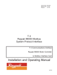
1
B6000
TM
Catalog No.: 5000.51J
Effective:
10-14-05
Replaces:
06-15-03
BOILER
MANAGEMENT
SYSTEM
SYSTEM CONTROL
BOILER MONITOR
Installation and Operating Manual
Part No. 240564
is a registered trademark of UnderWriters Laboratories Inc. ®
is a registered trademark of UnderWriters Laboratories-Canada Inc.®
______________________________________________________________________________________
Before operating this product, please read these instructions completely.
Page 2
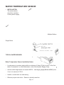
B6000 BOILER MANAGEMENT SYSTEM (BMS)
Contents
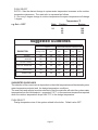
Equipment
Quantity
B6000 System Control
B6000 Boiler Monitor, Installed on Boiler(s)
Outdoor Temperature Sensor Assy. (064140)
Water Temperature Sensor Assy. (064139)
Optional Equipment
1
As Ordered
1
1
As Ordered
Check packaging for damage or missing components.
IMPORTANT NOTICE:
These instructions are intended for the use by qualified personnel only,
specifically trained and experienced in the installation of this type of equipment and related system
components. Installation and service personnel may be required by some states to be licensed. If your state
is such, be sure your contractor bears the appropriate license. Only qualified persons shall attempt to repair
this equipment. Repair must be according to these instructions.
WARNING:
Improper installation, adjustment, alteration, service or maintenance may damage the
equipment, create a hazard resulting in asphyxiation, explosion, fire, electric shock, personal injury or property
damage and will void the warranty.
CAUTION: MORE THAN ONE (1) SUPPLY SOURCE. THIS CONTROL HAS THE POTENTIAL TO BE
CONNECTED TO MORE THAN ONE (1) ELECTRICAL SUPPLY SOURCE. TO REDUCE THE RISK OF
ELECTRIC SHOCK, DISCONNECT ALL CONNECTIONS BEFORE SERVICING.
CAUTION:
RISK OF ELECTRIC SHOCK. MORE THAN ONE (1) DISCONNECT SWITCH MAY BE
REQUIRED TO DE-ENERGIZE THE EQUIPMENT BEFORE SERVICING.
PLEASE REGISTER
Before proceeding any further, please take a moment to complete the enclosed user registration form and
mail to Raypak, Inc., 2151 Eastman Avenue, Oxnard, CA 93030.
Page 3
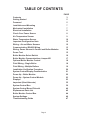
TABLE OF CONTENTS
Contents
Getting Started
Foreword
Installation and Mounting
Mechanical Installation
Electrical Installation
Check Your Power Source
Air Temperature Sensor
Water Temperature Sensor
Important Configuration Note
Wiring - Air and Water Sensors
Communication (RS485) Wiring
Wiring: Power Source to Control and Boiler Modules
Power Test
Boiler Monitor Select Switch
Boiler Monitor Communications Jumper W1
Optional Boiler Monitor Control
Field Wiring - Single Boiler
Field Wiring - Multiple Boilers
Installation Verification Procedure
System Control/Display Familiarization
Power Up - Boiler Monitor
Power Up - System Control Module
Displays
Important (Start Alternate)
System Control Box
System Control Board Pictorial
Replacement Parts List
Boiler Monitor Control Box
System Settings
Troubleshooting Guide
Page 4
PAGE
3
5
5
7
7
8
8
9
10
12
12
13
14
15
16
17
18
18
19
20
21
22
23
23
35
39
40
42
44
46
47
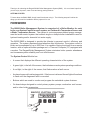
Thank you for selecting the Raypak B6000 Boiler Management System (BMS). It is our sincere hope that
you will enjoy its power, ease of use and energy saving features.
GETTING STARTED
To learn about the B6000 BMS, simply install it and start using it. The following steps will outline the
things you will need for installation and to prepare it for use.
FOREWORD
The B6000 Boiler Management System is comprised of a Boiler Monitor for each
boiler, one System Control for each system, an Outdoor Air Temperature Sensor and
a Water Temperature Sensor. The system is a microprocessor-based energy management hot water control system that controls single or multiple boiler installations used for
hydronic heating and/or domestic hot water supply.
The B6000 BMS is designed to provide the ultimate in personal comfort, efficiency and
operation. The system requires minimal attention after initial setup. The system control to
boiler can be separated by up to 2000 feet. It is capable of being monitored from a remote
location, with an optional modem package and a Personal Computer (PC) equipped with
a modem. The Raypak Boiler Management System minimizes boiler operator attendance
and increases system reliability and cost effectiveness.
The System Control Module has
•
A screen that displays the different operating characteristics of the system.
•
A green light, to the left of the screen, that indicates normal system operating conditions.
•
A red light, to the right of the screen, that flashes when a fault occurs.
•
An alarm buzzer with a silencing switch. If the buzzer is silenced the red light will continue
to flash until the diagnosed fault is corrected.
•
Buttons which are used to monitor and program the selectable system features.
•
On board relays designed to control primary system pumps, combustion vent louvers
and/or other boiler accessories.
Page 5
Each Boiler Monitor Module contains
• The boiler on-off power switch.
• The boiler manual override switch, which allows the boiler to operate independently
in the event of a system control failure.
• Standard indicator lights:
"Power On" - green, indicates the boiler is powered.
"Manual Override" - red, indicates boiler is in manual override mode.
"Call for Heat" - amber, indicates there is a call for heat.
"Pump" - green, indicates pump circuit is energized.
"High Limit" - red, indicates boiler is off on high limit.
"Aqua Stat" or "Thermostat" - red, indicates boiler is off on operating control (may not
appear on all models).
"Flow" - red, indicates boiler fault - no flow.
"Ignition" - red, indicates ignition failure.
"Pilot" - yellow or amber, indicates pilot is lit.
"Safety Fault" - red, indicates fault in safety valve or safety circuit.
"Main Gas" - green, indicates modulating valve is energized.
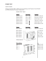
• Boiler identification dip switch.
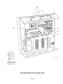
B6000/A Illustrated
Page 6
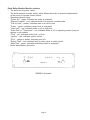
INSTALLATION AND MOUNTING
The System Control module should be mounted on a permanent base not subject to
vibrations, moisture or dust. It should be mounted with the display screen at a convenient
height for reading and for access to the alarm silence button located on the top of the cabinet.
Dimensions & Weight
Boiler Monitor
18-3/4" W
5-1/2" D
17-1/2" L
21-1/4 lbs.
System Control
12-1/2" W
4-3/4" D
15-3/16" L
20 lbs.
MECHANICAL INSTALLATION
Install the B6000 System Control Module at a convenient place within 2000 feet of the
boiler(s). The B6000 System Control Module must be mounted vertically with conduit holes
facing downward. Conduit holes are provided to accommodate standard conduit fittings.
Additional or larger conduit fittings that may be required should be located on the bottom of
the module.
Mount the B6000 System Control with 3/8" or 1/4" hardware in four (4) places.
A minimum of six (6) inches clearance on all sides is required and a minimum of eighteen
(18) inches clearance from the front is required for service access. The hinged side of the
box is to the right and the clearance (minimum 3" from bolt hole on the right side) should be
sufficient to open the cover.
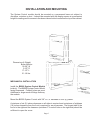
Page 7
A sub-panel containing the disconnect switches and surge suppressors is required at or
near the equipment location(s).
For accessibility remove the lower interior panel, by removing the four (4) access screws.
INSTALL CONDUIT AS APPROPRIATE.
NOTE: Shielded cable, Belden #8132 or #9842 or equivalent, must be used to connect the
sensors to the System Control Module.
DIMENSIONS AND WEIGHT
System Control Module
15 3/16 L
12 1/2 W
4 3/4 D
19 1/2 lbs
Boiler Monitor Module
17 1/2 L
18 3/4 W
5 1/2 D
21 1/4 lbs
ELECTRICAL CHARACTERISTICS
Control Module - 120 VAC, 0.5A; 60 Hz
Boiler Monitor Module - 120 VAC, 2.0A; 60 Hz
ELECTRICAL INSTALLATION
115 VAC FEEDER CIRCUITS
Install surge protection device(s) sized appropriately for your installation.
Install separate disconnect means for each load. Pull in appropriately sized wire for
equipment as defined by NEC and/or local code. All primary wiring will be 125% of minimum
rating.
It is strongly recommended that the System Control Module and the Boiler Control Module
be supplied from the same source power.
CHECK YOUR POWER SOURCE
Using a volt-ohm meter, check the following
voltages at the circuit breaker
CB
Hot
Neutral (Return)
VOM
WHITE
GROUND
PIDOMA
BLACK
A
GREEN
B
AC = 108 Volts AC Minimum, 132 Volts MAX
Hot to Ground
AB = 108 Volts AC Minimum, 132 Volts MAX
Hot to Neutral
BC = Must be less than 1.0 Volts AC
Neutral to Ground
Page 8
C
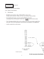
AIR TEMPERATURE SENSOR
•
INSTALLATION
Fig. #9040
TYPICAL AIR TEMPERATURE SENSOR
Air Temperature Sensor Installation Notes:
•
Locate on coldest side of building, usually (North or West) side.
•
Install the sensor in a shaded area, out of direct sunlight.
•
Locate no higher than 2/3 way up side of building or between 2nd and 3rd floor if building
is more than 3 stories tall.
•
Shielded cable length not to exceed 4000 feet.
•
Do not locate under an overhang, near wall corners, near drafts from stacks, air
moving devices, windows, doors, or balconies.
•
Assure cable length does not exceed 4000 ft. Use larger gauge (Belden #9842)
cable if run is in excess of 100 ft.
•
Install in conduit with no other wiring.
•
Observe proper wire colors. Sensor is polarity sensitive.
Page 9
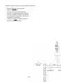
WATER TEMPERATURE SENSOR
•
INSTALLATION
The water sensor
should be installed
in the system supply.
Re
tu
p
Su
pl
y
rn
Multiple Boilers
Single Boiler
Water Sensor
TYPICAL WATER SENSOR
Water Temperature Sensor Installation Notes:
•
Locate sensor in system piping within a minimum of three (3) feet or prior to the first
take off connection, on the downstream side of the System Supply Loop.
•
Assure cable length does not exceed 4000 ft. Use larger gauge (Belden #9842) wire
if run is in excess of 100 ft.
•
Install in conduit with no other wiring.
•
Observe proper wire colors. Sensor is ploarity sensitive.
Page 10
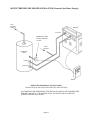
WATER TEMPERATURE SENSOR INSTALLATION (Domestic Hot Water Supply)
HOT
WATER
SUPPLY
BOILER
OUTLET
IMMERSION WELL
WATER SENSOR
1/2 NPT
INLET
COLD
WATER
STORAGE
TANK
INLET
OUTLET
B6000
SIMPLIFIED DIAGRAM OF TYPICAL PIPING
(PIPING LAYOUT MAY VARY PER SPECIFIC APPLICATION)
AIR TEMPERATURE SENSOR MUST BE INSTALLED ACROSS AIR TEMPERATURE
SENSOR CONTACTS. THE SENSOR IS NOT ACTIVATED AND CAN BE LEFT
STORED IN B6000 ENCLOSURE.
Page 11
IMPORTANT
Configuration Note:
If your System Control Module is supplied with a single Field Wiring
Teminal Strip use "Alternate" wiring. (See page 36-38)
WIRING - AIR AND WATER SENSORS
TO THE SYSTEM CONTROL MODULE
WATER
SENSOR
OUTDOOR
SENSOR
SYSTEM CONTROL
TERMINAL TB 2
BELDEN #8132
OR BELDEN #9842
NOTE: Tighten terminal strip
clamping screws 20 lbs - In
(2.26N.m) Breakage from over
torquing is not covered under
warranty.
Use copper conductors only.
For supply connections use
wires sized on the basis of 60°C
Ampacity and rated Min. 90°C
(194°F).
Page 12
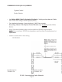
COMMUNICATION (RS 485) WIRING
System Control
Boiler Monitor
•
Use Belden #9842 Cable Or Equivalent (See Note). Polarity must be observed. Make
use of wire color coding to ensure proper polarity.
•
The shielding foil wrapper - bare wire (drain) - MUST be grounded.
Grounding is done at the System Control Module only. DO NOT ground at Boiler
Monitor.
•
Note: Equivalent shielded cable must be suitable for RS 485 communication
applications; must have 100-140 ohm impedance; and less than 30 picofarad per foot
capacitance.
•
Install in conduit with no other wiring.
BELDEN #9842
NOTE: Tighten terminal strip
clamping screws 20 lbs - In
(2.26N.m) Breakage from over
torquing is not covered under
warranty.
Use copper conductors only.
For supply connections use
wires sized on the basis of 60°C
Ampacity and rated Min. 90°C
(194°F).
BOILER MONITOR
TERMINAL TB 3
SYSTEM CONTROL
TERMINAL TB2
RS 485 Communications Cable Schematic
Page 13
WIRING: P
ower Sour
ce to System Contr
ol and Boiler ModPo
Source
Control
ules.
NOTE: Tighten terminal strip
clamping screws 20 lbs - In
(2.26N.m) Breakage from over
torquing is not covered under
warranty.
Use copper conductors only.
Dia. #9
For supply connections use
wires sized on the basis of 60°C
Ampacity and rated Min. 90°C
(194°F).
•
Observe proper Polarity.
•
Observe proper wire colors.
•
Provide external surge suppressor capable of maintaining system integrity.
•
Provide overload protection and disconnect means as required by code and for
equipment serviceability.
•
Conduit can not be used as the ground. (Must be "WIRED" ground).
•
Very Important: Grounding electrode conductor - shall be used to connect the
equipment grounding conductors, the equipment enclosures, and where the system
is grounded, the grounded service conductor to the grounding electrode.
Page 14
POWER TEST
CHECK POWER
Utilizing a Volt-Ohm-Meter (VOM) monitor the following on the "System Control Module"
and "Boiler Monitor(s)" for proper voltage levels.
POWER TEST TABLE
Module
Test Points
Indication
System Control
TB1-1- TB1-2
108 VAC to 132 VAC
System Control
TB1-1- TB1-3
108 VAC to 132 VAC
System Control
TB1-2- TB1-3
LESS THAN 1 VAC
System Control
TB1-1 - I
108 VAC to 132 VAC
System Control
TB1-2 - I
LESS THAN 1 VAC
System Control
TB1-3 - I
LESS THAN 0.5 VAC
Module
Test Points
Indication
Boiler Monitor
TB1-1- TB1-2
108 VAC to 132 VAC
Boiler Monitor
TB1-1- TB1-3
108 VAC to 132 VAC
Boiler Monitor
TB2-2- TB2-3
LESS THAN 1 VAC
Boiler Monitor
TB1 -1 - I
108 VAC to 132 VAC
Boiler Monitor
TB2 -2 - I
LESS THAN 1 VAC
Boiler Monitor
TB3 -3 - I
LESS THAN 0.5 VAC
FROM: BOILER MONITOR to SYSTEM CONTROL
Boiler Monitor
System Control
Indication
TB1 - 1
TB1 - 1
LESS THAN 0.5 VAC
TB1 - 2
TB1 - 2
LESS THAN 0.5 VAC
TB1 - 3
TB1 - 3
LESS THAN 0.5 VAC
TB1 - 2
TB1 - 3
LESS THAN 0.5 VAC
Page 15
IMPORTANT: The Boiler Monitor control board has a series of dip switches which identify the boiler(s) (SW2). It is required that the switches be set as shown in the switch
position table shown below.
BOILER MONITOR CARD PICTORIAL
BOILER MONITOR SELECT SWITCH
SWITCH
8
7
6
5
4
3
2
1
SWITCH
1
O
O
O
O
O
O
O
O
O = Open
Page 16
SWITCH POSITION
BOILER NUMBER
2
3
4
5
O
O
O
O
O
O
O
O
O
O
O
O
O
O
O
O
O
O
O
O
O
O
O
X
O
X
X
O
X
O
X
O
6
O
O
O
O
O
X
O
X
X = Closed
7
O
O
O
O
O
X
X
O
8
O
O
O
O
O
X
X
X
BOILER MONITOR COMMUNICATIONS JUMPER W1
•
Located in the upper left hand corner of the "LAST" Boiler Monitor board.
•
NOTE: The jumper indicates to the System Controller logic that the "Last" wired
boiler has been communicated with over the RS485 BUSS Link.
•
Definition: The "LAST" wired boiler is physically wired with the greatest wire
length from the "System Control" or is the last wired boiler for a single or multiple
boiler installation.
•
On a single boiler make sure the W1 Jumper has been installed.
W1
BOILER MONITOR CARD PICTORIAL
On boiler systems the jumper (W1) MUST BE installed on the "Last" wired boiler. This
is located on the Boiler Monitor board in the upper left hand corner, adjacent to the
RS485 terminals.
On Multiple boiler systems the W1 jumper must be removed from all Boiler Monitor
boards except on the "Last" wired boiler.
For normal boiler operation the dip switch settings can be utilized to define any of the
boilers as #1 thru # (maximum), independent of the "Last" wired boiler position.
Page 17
OPTIONAL BOILER MONITOR
•
Wiring
•
Contact Authorized Raypak representative for other wiring options
NOTE: Tighten terminal strip
clamping screws 20 lbs - In
(2.26N.m) Breakage from over
torquing is not covered under
warranty.
Use copper conductors only.
For supply connections use
wires sized on the basis of 60°C
Ampacity and rated Min. 90°C
(194°F).
Dia. #2
Field Wiring - Single Boiler
Dia. #7
Page 18
Field Wiring - Multiple Boilers
Dia. #7
Page 19
INSTALLATION VERIFICATION PROCEDURE
REGISTER
Before proceeding any further, please verify that the user registration form has been
completed and mailed (reference: Registration Card ).
MECHANICAL INSTALLATION
Verify installation has been completed (reference: Mechanical Installation ).
AIR TEMPERATURE SENSOR
Verify installation parameters have been met (reference: Air Temperature Sensor).
WATER TEMPERATURE SENSOR
Verify installation parameters have been met (reference: Water Temperature Sensor).
Verify System Control/Boiler Monitor power wiring connections.
Verify Torque Requirements.
Verify Air Temperature Sensor wiring, must be Belden #8132, #9842 or equivalent.
Verify Water Temperature Sensor wiring, must be Belden #8132, #9842 or equivalent.
Verify Power Test has been completed successfully.
Verify RS485 Communications Cable, must be Belden #9842 or equivalent.
Verify Boiler Monitor Select Switch (SW2) settings.
Verify Installation/Removal of Boiler Monitor Communications Jumper(s) [W1].
Verify Optional Boiler Monitor Control Wiring.
MODEM (Optional)
Perform and/or verify modem installation and hook-up per Raypak Add/On Options
P/N 240596 and B6000 BMS Optional Modem Software Documentation P/N 240595.
Page 20
SYSTEM CONTROL/DISPLAY FAMILIARIZATION
The System is set up by using the selector buttons and the displays on the System Control
module.
There are ten or more displays. Each display provides information regarding the system
operating parameters and system component status. Some displays provide information
only, such as current outdoor temperature, system temperature, etc..
Selectable data is identified by flashing characters.
The selector buttons are:
"MENU" - which when pressed will change displays.
"SELECT" - moves the cursor - flashing character - to the next selection in a display.
"+" - moves a value to a higher reading (e.g. Display shows flashing boiler #1. Pushing
"+" will change display to boiler #2).
"–" - moves a value to a lower position (e.g. Display shows flashing boiler #2. Pushing
"–" will change display to boiler #1).
EDITING B6000 DISPLAYS LOCATION
The B6000 BMS has a forty (40) character screen that displays status and memory contents.
Selectable Parameters on the B6000 Monitor Screen are as follows:
Selectable Parameters
Range
Value
Change to Fahrenheit (F) or Celsius (C).
Default (After Initialization)
Maximum Water Temp
Set
Day Temperature
Nite
Ratio
° Rise
Step
O/C (Outdoor Cutoff)
O/Cdb (O/C dead band)
CBand (Control Band)
Lead
Change Hours
Pump Delay *
Ign Time*
Degrees…………180
Degrees…………100
Degrees…………100
Degrees………… 90
Numeric…………1.0:1
Degrees………… 20
Percentile……… 20
Degrees………… 65
Degrees………… 4
Degrees………… 3
Numeric………… 1
Numeric…………100
Minutes………… 3
Seconds………… 30
70 - 235
40 - 220
40 - 220
40 - 220
None - 20:1
1 - 99
1s,2s, 5 - 100
35 - 199
1-9
1-9
1-8
0 - 225
0 - 20
15 - 100
*Indicates multiple entries
When the B6000 BMS is equipped with a night setback feature, [ WHEN INITIALIZED],
NITE SETBACK defaults to OFF.
Page 21
NOTE: Nite setback feature must be set at the B6000 BMS Control Panel to "ON". This results
in display change that shows NITE rather than DAY. The BMS can change "SETBACK TIMES"
up to six selections for each of the seven days.
WARNING
WARNING
WARNING
WARNING
WARNING
WARNING
When the initialize control selection is set to "Y" and "SELECT" button is pushed, the B6000
BMS resets all of the SELECTABLE PARAMETERS on this screen to DEFAULT values.
Nite Setback (NSB), Lead Lag is set to "OFF" (If option installed).
POWER-UP
Boiler Monitor
a. Energize by pushing Power Switch to "ON" position. The following indicator lights will
be
lit: - Power On
The following indicator lights will be lit if the boiler is performing the valve calibration cycle.
- Call for Heat
- Pump
- Pilot
b. Boiler will start provided there are no "faults" after the System Control module has
been energized.
V X . X X X X
I n i t i a l i z e ?
N
Version # of Software
System Control Module
Flashing (N,Y)
a. Energize the system control module.
- The screen should show the System Temperature (Display #1)
b. Press the "MENU" button until the screen shows the Initialize screen .
c. Press "+" or "–" button to change the cursor to "Y".
d. Press "Select" button.
- This will initialize the control memory to the default values.
Page 22
DISPLAYS
System Temperatures
* Indicates selectable item
Program the System Control Module to meet the design conditions of the installation.
Return to System Temperature Display by pressing the "MENU" button until screen appears
as below.
Ou t d o o r
Wa t e r [ T A R ]
X X X
° F
X X X
[ X XX ] X
Current Outdoor Air
Temperature
Current System
Water Temperature
Target Temperature
System Design
Temperature
Displays "H"
if over Hi Limit,
"M" if over MAX
Selectable °F or °C
Default is °F
INFORMATION ONLY
This is the first screen displayed when system is energized. After system is set up this
display should be used. °F or °C is selectable by pressing "+" or "–".
Provides:
Press MENU
- Outdoor temperature – actual
- System Water temperature – actual
- Target Temperature, which is the desired system temperature.
button
Boiler Valve
Firing Rates
V a l v e
P o s i t i o n
# X :
X X X %
Indicates Boiler being monitored
Provides valve firing position
On multiple boiler installations press "+" or "–"
to view position of other boiler firing rates.
INFORMATION ONLY
- Provides firing valve position for each boiler.
- Multiple boilers - press SELECT button to determine status of each boiler.
Press MENU button
Page 23
Boiler Status
S T A T U S :
- -
B o i l e r
OK
- -
Operating status of boiler
Ok or Fault Indicator
# X
*Boiler
Pushing "+" or "-" buttons will show
status of other boiler(s) in system
READOUT
Readout
OK - boiler operation
normal
FAULT indications: MAX TEMP - Target exceeds Max Temp -Not a faultTHERMOSTAT - Operating aquastat - Not a fault LWCO - low water cutoff - when supplied
LO PRES WTR - Low pressure water - when supplied
LO PRES GAS - Low pressure gas - when supplied
HIGH PRES GAS -High pressure gas
HIGH LIMIT FLOW SWITCH - Flow switch
NO PILOT MANUAL OVERRIDE - Boiler in emergency or manual operation
•
•
•
•
When a fault is indicated, the red light, to the right of the display, flashes and the alarm
buzzer sounds. The light continues to flash after alarm is silenced and until the fault is
corrected.
When fault is corrected display will read "OK"
Should communication between the system control module and the boiler monitor
module(s) be disrupted, the display will show "BOILER NOT ON-LINE".
To display status of other boilers press the (+) or (–) buttons on multiple boiler installations.
Page 24
System Control
Display
OK
System operating normally
LWCO
Low water in boiler
LOW PRES WATER
Water Pressure too low
LO PRESS GAS
Gas pressure below setting
HIGH PRESS GAS
Gas pressure on manifold too high
HIGH LIMIT
Boiler temp excess high limit
THERMOSTAT OFF
Boiler off on aquastat
FLOW SWITCH
Flow through boiler insufficient
NO PILOT
Pilot light failed to start
BOILER NOT ON-LINE
Communication lost
GREEN RED AMBER GREEN
Power Manual
Call
Pump
On
Overfor
On
ride
Heat
x
x
x
x
x
x
x
x
x
x
x
x
x
x
x
x
x
x
x
x
x
x
x
x
x
x
x
x
x
x
RED
Low
Water
Cutoff
x
x = Light On
PUMP light used only when Economaster programmed.
If a boiler should lose communication with the System Controller, BOILER NOT ONLIN
Page 25
Primary Control Parameters
S e t
*System water temperature
desired at outdoor
temperature of 70°.
Range 40 - 200
Default value 100°.
R a t i o
° R i s e
*RESET RATIO
* Rise is the temperature rise in
Ratio of outdoor temperature
system when all boilers are at full
to water system temperature.
rate. (ÐT of system) Range 1 -99
Range: 0.0:1 to 20: and "None"
Default value is 20°F
for constant water temperature
for constant water temperature
(TAR T - Set Point). Default value is 1.0:1.
LEAD LAG, NIGHT SET BACK
NOTE"S"
This "shadow box" indicates the display
for "Lead Lag, Nite Setaback" feature.
* System water temperature desired
at outdoor temperature of 70°.
Default value 100° (Day).
Default value 90°F (Nite).
LEAD LAG, NIGHT SET BACK
Primary Control Parameters
D a y
X X X
N i t e
X X
R a t i o
° R i s e
X . X : X
X X
Day Value is used as the set point
when setback is OFF; Nite value,
when setback is ON.
– Sets up boiler and system,
SET – Sets desired water temperature @ 70°F - minimum design
Range 40 -220 (Day), 40 - 220 (Night)
Default value is 100° (Day); 90°F (Nite)
To increase PUSH [+] button to required temperature - suggested setting is 110°F.
Page 26
PUSH SELECT
RATIO – Sets the desired change in system water temperature increases as the outdoor
temperature decreases. The reset ratio is expressed as follows:
2:1 for every 2 degree change in outdoor temperature the sytem temperature will change
1 degree.
Temperature °F
e.g: Set = 135°F
Ratio
Outdoor
System
2:1
60
40
20
140
150
160
Suggested Guidelines
Typical
Reset Ratio Setpoint at Design Temp:
Temp@
Design Cond
Temp@
70°F
40°F
20°F
0°F
-20°F
Standing
Convection or
Baseboard
190
105
0.3:1
0.6:1
0.8:1
1.1:1
200
105
0.3:1
0.5:1
0.7:1
0.9:1
Fan Coil - Heating
190
105
0.3:1
0.6:1
0.8:1
1.1:1
Fan Coil - Heat & Cool
140
105
0.9:1
1.4:1
2.0:1
2.6:1
Radiant Floor
120
105
2.0:1
3.3:1
4.7:1
6.0:1
Radiant Ceiling
120
105
2.0:1
3.3:1
4.7:1
6.0:1
RADIATION
SUGGESTED GUIDELINES
The selection of the correct ratio is dependent on the initial temperature and the desired system
water temperature setpoint and the design temperature conditions.
The reset ratio and setpoint must be selected so that the controller will raise the system water
temperature from the initial setpoint – suggested 110°F – to the maximum temperature required
when the outdoor temperature drops from 70°F to the design temperature.
PUSH SELECT
Design temperature rise of the system related to the boiler. Default value 20°F.
Page 27
Secondary Control Parameters
S t e p
X X %
*Step
Increment of firing
valve opening.
Range 1s, 2s 5-100
Default value 20%.
O/ C
X X X
O / C d b
C b a n d
X
° F
X
*O/C
Maximum outdoor
temperature that heat is
desired, set at 70°,
Range 35° to 199°.
Default value is 65.
*O/Cdb,
Outdoor cutoff
deadband is the
number of degrees
below O/C where
O/C reset occurs.
Range 1-9
Default value is 4°F.
Page 28
*C Band is a range of
temperature above and
below the target
temperature.
Range 1-9
Default value is 3°F.
*STEP
Enter desired valve firing increments. Recommended setting is between 5% and 20% for
Modulating Boiler.
Or
Enter 1S If Gas Valve is an On-Off or Single Stage
Or
Enter 2S If Gas Valve is 2 Stage Firing
Or
Enter 20% If the control boilers include modulating and 2 stage or single stage boilers under
control of a single system control module.
*O/C
Enter desired outdoor cutoff temperature, usually 70°F, depending on geographical location.
When outdoor temperature exceeds desired setting, target temperature will show "O/C".
Note: Boiler will restart when outdoor temperature drops below O/CF Tep - O/C db.
*O/Cdb
Enter desired outdoor cutoff dead band, which is the number of degrees below O/C where
O/C resets, usually 1F.
*C Band
Enter desired Control Band, determines when boiler will fire below target temperature and
shut off above target temperature, usually 1°F.
NOTE: The above settings are recommended at initial installation. For maximum
performance and system efficiency these settings should be modified, as required, to meet
such parameters as system capacity, location and usage.
NOTE: Contact factory for recommended settings if this is a special application ie. Heat
pump applications.
Lead Boiler Select
L e a d
X
*Indicates boiler
#
o f
designated as "Lead".
B o i l e r s
X
*Indicates number of boilers being used.
Used when there are multiple boilers. Set number (#) of boilers to match actual installation.
Readout lists lead boiler. To change lead boiler PRESS [+] or [–] button until desired boiler
is displayed. In the event of a fault in the designated lead boiler the next boiler, numerically,
becomes the lead boiler.
Boiler being monitored is displayed. If multiple boilers, push [+] or [–] to select the desired
boiler.
Page 29
LEAD LAG, NIGHT SET BACK
Automatic Lead Lag
L e a d
C h a n g e
h r s .
H o u r s
R e ma i n i n g
X X X
X X X
*Lead Change Hours
Designated lead boiler will change when remaining hours reaches 0.
Range 0-225 hrs. Default value is 100 hrs.
If set at 0 hours lead will not change.
Hours remaining will automatically total.
Enter the desired number of hours of lead boiler operation before change. Hours remaining is automatically calculated. Designated lead boiler will change as soon as
remaining hours run out. Set at 0 hours and lead will not change.
STANDARD
BOILER PARAMETERS
LEAD LAG, NIGHT SET BACK
Boiler Parameters
P u mp
D e l a y
# X :
X X
m i n
I GN
X X X
T i me
s e c
*Pump delay selectable from 0 to 20
minutes. Range 0-20. Default value 3 mins.
*Ignition time sets the duration to monitor
Ignition prior to lock out. Range 15-100.
Default value 30 secs.
PUSH SELECT
PUMP DELAY
Enter time desired for boiler pump operation, if one is installed and wired to boiler monitor. If there is no pump or a continuous running pump, ignore.
PUSH SELECT
IGN TIME
Display shows time of monitoring the ignition prior to main flame. Default timing is 30
seconds.
Note: On multiple boilers, a time must be entered for each boiler.
Page 30
Night Setback
"OFF" indicates the system is in the Normal or design operating mode. "ON" indicated
the system is operating in a programmed night setback mode.
LEAD LAG, NIGHT SET BACK
NOTE"S"
This "shadow box" indicates the display
for "Lead Lag, Nite Setaback" feature.
Automatic Lead Lag
* X X : X X P M
** M o n d a y
S e t b a c k : *** O F F
*Set Time of day
** Day of Week
*** On or Off
This screen shows the time and day of the week. Default values:
Monday for the day, and "OFF" for Setback.
Enter the current time.
PUSH SELECT Until day flashes.
Enter day of the week.
Setback status can be manually changed from "OFF" to "ON", or vice versa, provided the
setback times have been cleared, otherwise the timer will override the manually selected status
of setback. Push [+] or [–] to setback mode to "on" or "off".
LEAD LAG, NIGHT SET BACK
Setback Times
S e t b a c k :
1 : * X X : X X
* Mo n d a y
X X : X X
am or pm
am or pm
This screen shows the Setback "ON" and "OFF" times for each day.
There are six (6) "ON" and six (6) "OFF" times per day, as indicated
by the number on the left.
Page 31
Set Back Example:
Period
SETBACK
"ON"
SETBACK
"OFF"
DAY
1
2
xx:xx
10:00 pm
05:00 am
xx:xx
Monday
Monday
1
2
xx:xx
10:00 pm
05:00 am
xx:xx
Tuesday
Tuesday
1
2
xx:xx
10:00 pm
05:00 am
xx:xx
Wednesday
Wednesday
1
2
xx:xx
10:00 pm
05:00 am
xx:xx
Thursday
Thursday
1
2
xx:xx
10:00 pm
05:00 am
xx:xx
Friday
Friday
1
2
xx:xx
xx:xx
xx:xx
xx:xx
Saturday
Saturday
1
2
xx:xx
xx:xx
xx:xx
xx:xx
Sunday
Sunday
The above example will set back temp weekends and 10:00 pm to 5:00 am weekdays. Each
day can have up to six (6) separate setbacks.
When no time is entered (indicated by xx:xx) the setback time in effect from the previous time
period will continue on to the next period, which means, when the night setback is "ON" the
system water temperature for nighttime use will be maintained until the next "OFF" entry is
reached.
Page 32
Boiler Valve Timing
Boiler Valve Timing
Information only
V a l v e
# X :
X X u
u= UP
d = DOWN
T i m i n g
X X d
s e c .
Boiler Number
Displays in seconds real time opening and closing
of modulating gas valve from closed (0%) to full open (100%)
This display shows the time (secs) required for the gas valve to open and close. If "u"
display is from 12 to 26 and "d" is less than "u" and between 4 and 18 the gas valve
requires no adjustment. This timing is not operator changeable on the screen display.
Proportional Integral
Derivative Operator
Manual Action (PIDOMA)
A.Proportional Integral Derivative
Operator Manual Action
A P c o n s t
X /
X
*Pconst is the proportional ratio
which causes the boiler to step up
or down, faster or slower (overshoot or undershoot) and finally
end up offset from desired temperature. Default is 1/3.
Wa i t
X
D c o n s t
X /
X
*Wait is the time controller waits
until it acts on a temperature
change. Default value is 5 seconds.
*Dconst is the derivative ratio
which tells the system how first to
react to differing changes in water
temperature. Default is 3/1.
*Pconst
Proportional ratio which causes the boiler to step up or down, faster or slower.
*WAIT
Wait as time controller hesitates before acting on a temperature change.
*Dconst
Derivative ratio speeds or slows boiler response compensating for overshoot and undershoot.
Page 33
Proportional Integral
Derivative Operator
Manual Action (PIDOMA)
B.Proportional Integral Derivative
Operator Manual Action
B P c o n s t
X /
X
*Pconst is the proportional ratio
which causes the boiler to step up
or down, faster or slower (overshoot or undershoot) and finally
end up offset from desired temperature. Default is 1/3.
Wa i t
X
D c o n s t
X /
X
*Wait is the time controller waits
until it acts on a temperature
change. Default value is 5 seconds.
*Dconst is the derivative ratio
which tells the system how first to
react to differing changes in water
temperature. Default is 3/1.
*Pconst
Proportional ratio which causes the boiler to step up or down, faster or slower.
*WAIT
Wait as time controller hesitates before acting on a temperature change.
*Dconst
Derivative ratio speeds or slows boiler response compensating for overshoot and undershoot.
ALL BOILERS ON/OFF
A l l
B o i l e r s
o n / o f f
X X
a b o v e /
X X
b e l o w
Range 1 to 99. Default valve 20° F.
This Display Indicates:
The temperature above or below target at which the control will turn off or on all the boilers.
TARGET MIN/MAX AND HI LIM
T a r g e t Mi n / Ma x :
X X X / X X X
Min Default 105, range 0 to 220°F
Max Default 180, range 0 to 220°F
Hi Lim Default 200, range 0 to 220°F
H i L i m
XX X
Hi Lim shows the maximum obtainable water
temperature.
Hi Lim can not be lower than the target XXX/
Max.
Note: All of the values interact and are
depedent upon each other.
Page 34
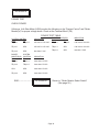
tandard
Initialize
LEAD LAG, NIGHT SET BACK
Initialize
V X . X X X X
I n i t i a l i z e ?
Y
Y - Yes
N - No
Version # of software.
* This will initialize all previous selectable values to default values. Should not be
used unless operator wants to reprogram new values. Should be used at Start-up
to clear the control memory.
This should be by-passed, if controls have been initialized as the first step.
Standard
Utility Service
LEAD LAG, NIGHT SET BACK
Utility Service
T e mp :
X X X
( X X X ) m : x
X X X %X X X %X X X %X X X %X X X %
Displays Firing Rate of each Boiler
Displays controller operating mode,
changes continously from 1 to 5.
Displays System Target Temperature
Displays Actual System Temperature
Information Only.
Displays the system operating conditions and the firing rate of each boiler up to total of (5).
Page 35
IMPORTANT
START
"ALTERNATE"
WIRING
-
If your system module(s) are supplied with a single
Field Wiring Terminal Strip use this method for wiring.
AIR AND WATER SENSORS
To The System Control Module
WATER
SENSOR
OUTDOOR
SENSOR
BELDEN #8132
or BELDEN #9842
BARE WIRE
(SHIELD/
DRAIN)
TO:
SINGLEPOINT
GROUND
(SPG)
AIR/WATER TEMPERATURE SENSOR SCHEMATIC
Page 36
FIELD WIRING
TERMINAL STRIP
Dia. #10
"ALTERNATE"
Continued
COMMUNICATION (RS 485) WIRING
From: System Control Module
To:
Boiler Module
•
Shielded communications cable - Belden #9842 must be used.
Polarity must be observed. Make use of wire color coding to ensure polarity.
•
The shielding [foil wrapper - bare wire (drain)] MUST be grounded.
Grounding is done at the (System Control) only. DO NOT ground at boiler monitor.
•
Note: Equivalent shielded cable must be suitable for RS 485 communication applications;
must have 100-140 ohm impedance; and less than 30 picofarad per foot capacitance.
•
Install in conduit with no other wiring.
SYSTEM CONTROL
TERMINAL
Dia. #11
RS 485 Communications Cable Schematic
Page 37
WIRING: Power Source to Control and Boiler Modules
•
•
•
•
•
*
Observe Polarity very important.
Observe wire colors
Provide external surge suppressor
capable of maintaining system integrity.
Provide overload protection and disconnect means as required by code and for
equipment serviceability.
Conduit can NOT be used as ground.
Must be "WIRED" Ground.
Dia. #12
Page 38
"ALTERNATE"
POWER TEST
CHECK POWER
Utilizing a Volt-Ohm-Meter (VOM) monitor the following on the "System Control" and "Boiler
Monitor(s)" for proper voltage levels. Check at the Terminal Block (TB).
POWER TEST TABLE
108 VAC to 132 VAC
BOILER MONITOR(S)
From:
To:
TB pin 1
TB pin 2
108 VAC to 132 VAC
SPG
108 VAC to 132 VAC
TB pin 1
SPG
108 VAC to 132 VAC
TB pin 2
SPG
less than 1 VAC
TB pin 2
SPG
less than 1 VAC
BOILER
MONITOR(S)
From:
TB pin 1
SYSTEM
CONTROL
To:
TB pin 1
TB pin 2
TB pin 2
Less than 0.5 VAC
SPG
SPG
Less than 0.5 VAC
TB pin 2
SPG
Less than 0.5 VAC
SYSTEM CONTROL
From:
To:
TB pin 1
TB pin 2
TB pin 1
END – – – – – – – –
INDICATION
INDICATION
INDICATION
Less than 0.5 VAC
"ALTERNATE"
Return to: "Boiler Monitor Select Switch"
(See page 20.)
Page 39
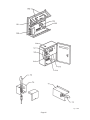
Fig. # 9458
Page 40
Fig. # 9459
Page 41
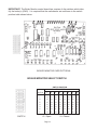
SYSTEM CONTROL BOARD
Fig. # 9460
Page 42
Replacement Parts List
New
Part
#
CP10.0_ _ _
CP10.0N _ _
CP10.0NMn
90FI
90EI
900D
Page 43
Replacement Parts List
Page 44
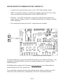
Fig. # 9461
Located in place of
ignition control on
C2 boilers only.
BOILER MONITOR CONTROL BOX
Page 45
Replacement Parts List
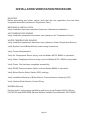
CALL OUT
B 6000 SYSTEM
PART NO.
Boiler Monitor Control Box
B-1
Control PC Board
004795F
B-2
Power/Manual or Override Switch
650745
B-3
Transformer, 120/8.5 VAC C.T.
064921
B-4
Transformer, 120/24 VAC C.T.
650495
B-5
Transformer, 120/24 VAC (C2 Units only)
650495
B-6
Ignition Control with Lockout
004818B
F1 & F2
Fuse, AGC 2, 250V, 2A
650896F
F3
Fuse, AGC3, 250V, 3A
650523
K-1, K-2, K-3, K-4
Relay, 5 VDC, SPDT
650846F
K-7, K-8
Relay, 24 VAC, DPDT
650849F
K-6
Relay, 120 VAC, SPDT
650848F
K-5
Relay, 24 VAC, SPDT
650847F
K-1, K-2, K-3,
K-4, K-5, K-6
Relay, Socket SPDT
650851F
K-7, K-8
Relay, Socket DPDT
650850F
U4
EPROM BVx.x
601194
Page 46
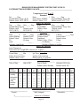
B6000 BOILER MANAGEMENT SYSTEM START-UP DATA
SYSTEM SETTINGS ENTERED ON DATE:_____________________________________
Temperature Scale °F or °C
Standard
Set _____ Deg.
Ratio
_____ : 1 Rise _____ Deg.
System Water Temp. @ Oc
Reset Ratio-Outdoor:
System Design Temp. Diff.
Default Value 100°F (38°C)
Default Value: 1.0:1
Default Value: 20°F (7°C)
Select Set Optional
Day _____ Deg.
Nite_____ Deg.
Ratio _____:1
Rise _____ Deg.
System Temps @ Oc
Reset Ratio
System Design Temp. Rise
Default Value
Default Value:
Default Value:
Default Value:
100°F (38°C)
90°F (32°C)
1 .0:1
20°F (7°C)
Universal
Step _____ %
O/C_____Deg.
O/Cdb _____Deg.
C Band
_____ Deg.
Valve Opening
Outdorr Cutoff
Outdoor Cutoff
Control Band
Default Value:
Default Value:
Deadband
Default Value:
5%
65 degs.
Default Value: 4 Deg
3 Deg.
Lead
_____
# of Boilers
_____
Indicates Lead Boiler
Number of Boilers in system.
Select Set Optional
Lead Change hrs. _____
Lead boiler will change after selected no. of hours.
Universal
Pump Delay _____ Min.
Ign Time _____ Sec.
Delay off pump timing.
Ignition lockout timing.
Default Value: 3 min.
Default value: 15 seconds.
Select Set Option
____________
__________
____________________ _______________
Time of Day
AM or PM
Day of Week
Set-back- Off or On
Default Value: Monday
Default Value: Off
Period
Set-Back
Monday
Tuesday
Wednesday
Thursday
Friday
Saturday
Sunday
1
On
___
___
___
___
___
___
___
Off
___
___
___
___
___
___
___
2
On
___
___
___
___
___
___
___
____________________
Pconst
V___________________
Off
___
___
___
___
___
___
___
3
On
___
___
___
___
___
___
___
Off
___
___
___
___
___
___
___
4
On
___
___
___
___
___
___
___
Off
___
___
___
___
___
___
___
5
On
___
___
___
___
___
___
___
Off
___
___
___
___
___
___
___
6
On
___
___
___
___
___
___
___
Off
___
___
___
___
___
___
___
Proportional Integral Derivative
____________________
____________________
Wait (Integral)
Derivative
Version # of Software
Page 47
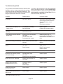
Troubleshooting Guide
The procedures outlined below assume that the initial
installation / turn on / power up procedures have been
completed and that the B6000 was operational. This
guide is a basic instruction to determine if an authorized
Raypak representative should be contacted.
If you follow the instructions in this manual and have
difficulty operating the B6000, locate the SYMPTOM in
the left column below. Check the corresponding POSSIBLE CAUSE and CORRECTIVE ACTION Column to
locate and remedy the problem.
Symptom
Possible Cause
Corrective Action
No Display.
No Primary power.
Check power connections to units.
Check surge protection devices.
Check disconnects, check
grounds.
Check power switches.
* Nite set-back time display no
longer correct.
Time display accidentally
Re-Programmed.
Initialize system.
Program Nite set-back feature.
* Nite set-back not working
properly.
Nite set-back turned off.
Clock times not set.
Initialize system.
* Time display does not maintain
proper time.
System ground not adequate.
Line noise.
Internal battery weak.
Prolonged power outage.
Initialize system and / or
contact authorized Raypak
Representative for further instructions.
System not working automatically.
Boiler monitor has Manual Mode
selected
Select Automatic mode on Boiler
Monitor.
Display shows incorrect number of
boilers.
Inadequate grounds.
Line noise
Power outages.
Check primary power - check
wired ground.
Rework as necessary.
Initialize system.
Scrambled control display.
Power outages.
Initialize system.
Boiler does not function properly
after power outage.
Internal battery weak.
Line noise.
System ground not adequate.
Initialize system.
Boiler "Not on Line" displayed.
Primary power at boiler not
connected.
Initialize system.
Outdoor and water temp.
readings Incorrect (-35°F).
Inadequate ground
Line noise.
Power outage.
Initialize system.
Displayed parameters
do not make sense.
Power outage.
Initialize system.
System Faults indicators do not
make sense.
Power outage.
Initialize system.
* With Nite Set-Back option only.
Page 48
Trouble Shooting Guide-Continued
Symptom
Possible Cause
Corrective Action
Boiler # x
"Not on Line" Displayed
Boiler not powered.
Check primary power.
Correct as necessary.
Check communication cable,
check (surge) ground Remove /
Replace (R/R) as necessary.
Initialize system.
Outdoor Temp. Sensor readings
are high.
Outdoor sensor not mounted
correctly.
Refer to installation manual
mounting instructions. Possible
relocation for sensor.
Sensor reading 220°F.
Sensor wiring shorted
Check sensor wiring for damage.
R/R as necessary.
Initialize system.
Sensor reading - 35°F.
Sensor wiring open.
R/R as necessary
Initialize system.
Low water cut-off alarm.
Excessive circuit loading of pump
contacts by user supplied system
pump.
Low water level in boiler
Check power.
Check pump contactor / relay
R/R as necessary.
Replace F1 fusing.
Check main water supply
Power lamp off on Boiler Monitor.
Fuse F1 blown.
Excessive circuit loading of pump
contacts by user supplied system
pump.
Circuit breaker tripped.
Replace F1 fusing.
Remove Relay-K1 to isolate circuit
loading.
R/R as necessary.
Reset circuit breaker.
Pump not running.
Excessive circuit loading of pump
contacts by user supplied system
pump.
Replace F1 fusing.
Pump going off on thermal overload circuit breaker tripped
Check pump.
Reset circuit breaker
Off at flow switch.
Paddle damaged or missing.
Pump off on thermal overload.
Check paddle on flow switch.
Check pump, contact or relay.
Replace F1 fusing.
Off on High Limit.
Low limit settings.
Intermittent power or pump
failure.
Check and correct settings.
Meter amperage on pump.
R/R as needed.
Page 49
LIMITED WARRANTY
B6000, Y-Series, E-4 & Accessories
SCOPE OF WARRANTY :
Raypak, Inc. ("Raypak") warrants to the original owner the Control System to be free from defects in materials and workmanship
under normal use and service for the applicable warranty period. In accordance with the terms of this Limited Warranty, RAYPAK will
furnish a replacement or repair, at our option, any defective part which fails in normal use and service during the applicable warranty period.
The replacement or repair will be warranted for only the unexpired portion of the original Warranty Period.
APPLICABLE WARRANTY PERIOD
The effective date of warranty coverage is the date of original installation, of the Control System, by a qualified electrician or by a
RAYPAK authorized service technician. The Applicable Warranty Period is one (1) year from the effective date.
WARRANTY EXCLUSIONS
This Limited Warranty does not apply:
1. if the control system is not properly installed by a qualified technician in accordance with manufacture's installation
instructions, applicable codes, ordinances and good trade practices,
2. to damage or malfunctions resulting from failure to properly install, operate or maintain the system in accordance
with the manufacture's instructions;
3. if the rating plate(s) or serial number(s) are altered, defaced or removed;
4. if the System is modified in any way or used with any non-factory authorized accessories or components;
5. to damage or failure from abuse, accident, act of nature, fire, flood, freezing or the like;
6. to accessories, rubber or plastic parts, light bulbs or glass parts;
7. if the System is moved from its original installation site; or if the original owner no longer owns the site or the System.
LABOR AND SHIPPING COSTS
This Limited Warranty does not cover labor costs for service, removal or reinstallation of any part nor shipping charges to or from
RAYPAK'S designated repair center or to or from the installation site. All such costs are your responsibility.
HOW TO MAKE A WARRANTY CLAIM
To make a warranty claim, promptly ship (postage prepaid) or carry the defective part to a designated RAYPAK Service Dealer or
Service Station in the United States, supplying proof of purchase and date of installation and the model and serial numbers. If you cannot
locate a dealer, contact RAYPAK'S Service Department at the address/telephone listed below. Raypak reserves the right at all times to
inspect the claimed defect and verify warranty coverage at its factory.
EXCLUSIVE WARRANTY - LIMITATION OF LIABILITY
This is the only warranty given by RAYPAK. No one is authorized to make any other warranties on Raypak's behalf. ANY IMPLIED
WARRANTIES, INCLUDING MERCHANTABILITY OR FITNESS FOR A PARTICULAR PURPOSE, SHALL NOT EXTEND
BEYOND THE APPLICABLE WARRANTY PERIOD SPECIFIED ABOVE. RAYPAK'S SOLE LIABILITY WITH RESPECT TO
ANY DEFECT SHALL BE AS SET FORTH IN THIS LIMITED WARRANTY. ANY CLAIMS FOR INCIDENTAL OR
CONSEQUENTIAL DAMAGES (INCLUDING DAMAGE FROM WATER LEAKAGE) ARE EXCLUDED. Some states do not allow
limitations on how long an implied warranty lasts, or for the exclusion of incidental or consequential damages, so the above limitation or
exclusion may not apply to you.
THIS LIMITED WARRANTY GIVES YOU SPECIFIC LEGAL RIGHTS, AND YOU MAY ALSO HAVE OTHER RIGHTS
WHICH VARY FROM STATE TO STATE.
We suggest you immediately complete the information below and retain this Limited Warranty Certificate in case warranty service
is needed.
RAYPAK, INC. SERVICE DEPARTMENT
2151 Eastman Avenue, Oxnard, California 93030
Telephone: (805) 278-5300 FAX (805) 278-5468
The following information must be provided when you write or call:
________________________________________________
Original Owner
_______________________________________________
Daytime Telephone Number
__________________________________________________________________________________________________
Complete Mailing Address
________________________________________________
City
State
Zip Code
_______________________________________________
Installation Site
________________________________________________
Model Number
_______________________________________________
Contractor/Installer
________________________________________________
Date of Installation
_______________________________________________
Serial Number
Raypak, Inc., 2151 Eastman Ave, Oxnard, CA 93030 (805) 278-5300 FAX (805) 278-5468
Litho in U.S.A.
www.raypak.com
Design and specifications subject to change without notice.
UL
®
This symbol on the nameplate means the product is listed by Underwriters
Laboratories, Inc. ®
Raypak, Inc., 2151 Eastman Avenue, Oxnard, CA 93030 • (805) 278-5300 • FAX (800) 872-9725
Litho in U.S.A.