1
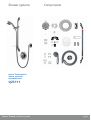
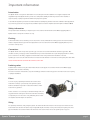
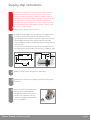
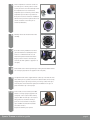
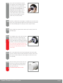
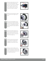
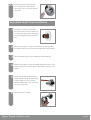
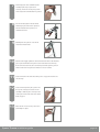
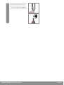
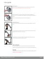
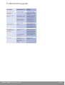
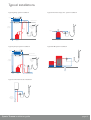
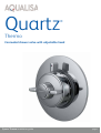
Quartz
®
Thermo
Concealed shower valve with adjustable head
Quartz Thermo installation guide
page 1
Shower systems
Components
Quartz Thermo built-in
shower valve with
adjustable head
QZ3111
Quartz Thermo installation guide
page 2
Important information
Introduction
The Quartz Thermo is designed for both built-in and concealed panel mount installation and is supplied complete with
adjustable height head. Quartz Thermo provides close temperature stability and fail safe protection when installed on
approved gravity or pumped systems and balanced high pressure systems.
A cold inlet flow regulator is provided for use with instantaneous (multipoint) gas water heater and combination boiler applications.
If you have any questions at any stage during installation please contact the Aqualisa customer helpline on 01959 560010.
Safety information
This product must be installed by a competent person in accordance with all relevant current Water Supply Regulations.
Quartz Thermo is designed for domestic use only.
Flushing
Some modern fluxes can be extremely corrosive and, if left in contact, will attack the working parts of this unit. All soldering
must be completed and the pipe work thoroughly flushed out in accordance with current Water Supply Regulations prior to
connection of the pro duct.
Connections
The Quartz Thermo valve incorporates ‘push fit’ type connections for use with 15mm British Standard copper tube. Tube
should be cut using a rotary type cutter and lubricated using a silicone based lubricant or petroleum jelly (Vaseline or similar)
prior to insertion into the fitting. Supply lines must be flushed clear of any debris before installation of the unit.
If plastic pipe is to be used, the tube insert must not increase the tube diameter or extend the cut off length by more than 2mm.
THESE FITTINGS ARE NOT SUITABLE FOR STAINLESS STEEL TUBE
Isolating valves
Suitable isolation valves such as gate valves must be fitted to both supplies in accordance with the current Water Supply
Regulations and our terms of warranty.
Due to their restrictive characteristics, stopcocks and ball type valves that reduce the pipe bore size must not be used on gravity
or pumped installations.
Filters
To ensure ongoing optimum performance the internal control
mechanism ‘cartridge’ is protected by a two-part filter system.
Debris accumulation may result in reduced flow from the shower
head and noisy operation.
As this condition is not covered by our standard warranty terms, it is
suggested that the cartridge be removed and the filters checked by
a competent person. In the event of any difficulties please contact
the Aqualisa customer helpline for assistance.
Siting
For optimum performance, with gravity fed systems, the distance between the bottom of the storage cistern and the shower
head should not be less than 1m (when using an adjustable height shower kit). If using a fixed head, the highest point of the
pipe work must be not less than 1m below the underside of the cistern. Please refer to the system layouts on page 15
Quartz Thermo installation guide
page 3
Important information
Pump installation
UNDER NO CIRCUMSTANCES MUST A PUMP BE FITTED DIRECTLY TO THE WATER MAIN.
A pump must only be used to boost the pressure from tank-fed supplies. A typical layout is shown on the reverse of this guide.
Stored water capacities
The minimum capacity of the cold storage cistern should not be less than 225 litres (50 gallons). The capacity of the hot
cylinder must be capable of meeting the anticipated demand.
Pressures
The Quartz Thermo shower valve is designed to control static pressure up to 10 bar. Where pressures are likely to exceed 10
bar, a pressure reducing valve (PRV) must be fitted into the incoming mains supply. A setting of 3 bar is recommended. It
should be noted that daytime pressures approaching 8 bar can rise above the stated maximum overnight.
Quartz Thermo is not suitable for mixed supply systems e.g. gravity hot and mains cold.
A suitable PRV is available from Aqualisa.
Gravity fed hot and cold supplies
Services must be installed according to good plumbing practice having regard to pipe sizing, long pipe runs and low-head
situations.
The cold supply for the valve assembly must be taken directly from the cold storage system. The hot supply may be taken from
the vent/draw off pipe of the hot water cylinder at a point below the cylinder connection or alternatively from the underside of
the horizontal draw off.
Rising pipe work must not be connected into the horizontal draw-off from the cylinder or to any point in the vent/draw off pipe
above the cylinder connection.
CYLINDER TEMPERATURE IN EXCESS OF 65ºC MAY RESULT IN POOR SHOWER PERFORMANCE.
To minimise pressure loss we recommend that the hot and cold supplies are run in 22mm as close as reasonably possible to the
mixing valve before reducing to 15mm.
A typical layout is shown oon page 15.
Combination boiler/multipoint system
The gas water heater must be capable of raising the temperature of the incoming water by 35˚C and delivering a flow rate of
no less than 9 litres (2 gallons) per minute to the shower valve. This is sufficient to operate one outlet point at a time.
The Aqualisa Thermo cartridge is designed to operate from the mains at a maximum pressure of 10 bar. If the mains pressure
exceeds 10 bar a ‘drop tight’ PRV must be fitted on the supply pipe after the main stopcock.
The cold supply can be taken from the nearest convenient mains supply and the hot supply can be taken from the nearest
hot water draw-off point. Account must be taken of the pressure drops that will occur when other draw-off points are used
while the shower is in use. Pipe work can generally be run in 15mm.
A typical layout is shown oon page 15.
Balanced high-pressure system
The Aqualisa Thermo cartridge is designed to operate with unvented hot water
storage systems up to a maximum pressure
of 10 bar. A PRV must be used if either supply exceeds 10 bar. The cold water supply must be drawn from the same mains
supply as that to the hot water system (down stream of the cylinder manufacturers pressure limiting valve, where supplied)
and the hot supply from the nearest convenient draw off point. Account must be taken of pressure drops that may occur when
other draw-off points are used while the shower is in use.Pipe work can generally be run in 15mm.
A typical layout is shown oon page 15.
Quartz Thermo installation guide
page 4
Step-by-step instructions
!
In addition to the guide below it is essential that the written instructions
overleaf are read and understood and that you have all the necessary
components (shown overleaf) before commencing installation. Failure to
install the product in accordance with these instructions may adversely affect
the warranty terms and conditions. Do not undertake any part of this
installation unless you are competent to do so. Prior to starting ensure that
you are familiar with the necessary plumbing regulations required to install
!
1
the product correctly and safely.
Quartz Thermo is supplied with universal fixings.
If installing the product built in to a solid wall, chase out a suitable recess in
the wall to receive the valve and pipe work. If installing the valve in a
concealed panel mounted situation, in most cases it will be necessary to first
install a suitable sound fixing in the cavity area before fixing the valve.
A hole of ø130mm is required to install the valve and gain access to inlet and
outlet connectors.
The valve needs to be mounted to the depth shown at the following centres.
The distance between the 15mm inlet centre pipe centres is 150mm as shown.
65mm
150mm
100mm max.
to finished/
tiled wall
surface
Supply pipes hot on
left, cold on right
65mm
60mm
min. from
back face
of valve to
finished/
tiled wall
surface
(10mm
allowance
for tiles)
2
Mark the position for the four fixing points as outlined above.
3
Carefully remove the valve from its packaging and retain the mortar guard
4
Remove the on/off lever assembly, if fitted,
for later use.
from the valve by carefully pulling the
assembly away from the valve (a screw is
provided in the screwpack to secure the
on/off lever assembly to the valve towards
the end of installation).
Quartz Thermo installation guide
page 5
5
Set the temperature control lever to full cold
(9 o’clock) prior to removing the four screws
securing the lever to the valve. Carefully remove
the temperature lever to reveal the lilac
temperature preset override ring and the white
temperature preset location ring. Neither of
these parts need to be removed for installation.
However if they are removed please take a note
of their orientation on the valve prior to
removal (as illustrated).
6
Carefully remove the shroud from the valve
7
If the valve is being installed for use with a
assembly.
gas fired instantaneous (multipoint) water
heater or a combination boiler, the cold
water flow regulator must be fitted at this
stage by insertion into the cold water port
as shown (the flow regulator is supplied in its
own pack).
8
Fit the elbows to the valve body hand tight, ensuring that the rubber washers
9
The Quartz Thermo valve is supplied with an outlet cap on the bottom of the
are correctly engaged (these are supplied in the screw pack).
valve allowing for a top outlet connection. The bottom outlet can be used by
simply removing the cap and repositioning it on the top outlet. If the cap is
removed please ensure that when replaced, the membrane in the cap is in
place and that the cap is done up tight.
10
Fit the outlet connector ensuring the rubber
washer is correctly engaged (supplied in the
screwpack), on the required outlet ensuring
a tight fit. Offer the valve up to the required
fixing position to check the four fixings
points are correct and there is adequate
space available around both inlet elbows
and outlet connector.
Prepare the wall fixings as required.
Quartz Thermo installation guide
page 6
11
Using a silicone based lubricant, lubricate
the supply pipe ends and whilst supporting
the elbows, push home the supply pipes
ensuring the correct orientation for the inlet
pipes (HOT LEFT AND COLD RIGHT AS
SHOWN ON THE VALVE BODY). Push the
valve fully home until a definite stop is
reached (tube insertion depth is 25mm).
Secure the valve assembly to the fixing
surface using the screws provided.
12
Construct a suitable 15mm outlet supply to a suitable point for the wall outlet.
Using a silicone based lubricant, lubricate the 15mm outlet pipe and push into
the outlet assembly fully home (outlet pipe insertion depth is 24mm).
13
Using a suitable tool, tighten both the elbow nuts and outlet connector nut
14
The installation may now be checked for leaks.
until water tight.
Temporarily cap off the outlet supply pipe.
Push the on/off lever assembly onto the front
!
of the valve fully home and turn the knob fully
clockwise to ensure the valve is fully turned off.
The on/off shaft is manufactured with a flat
area. The corresponding flat area in the on/off
lever must be in alignment before the knob
can be fitted.
15
Turn on the supplies and check for any leaks upstream of the valve. Slowly
open the control and check for leaks downstream of the valve. If all is sound,
turn off the on/off knob fully, turn off the supplies and remove the on/off
lever assembly.
16
Place the mortar guard around the valve and
fill in the chase. Once the in-filling material
has set, carefully remove the polystyrene to
expose the valve body.
!
THE MORTAR GUARD MUST BE USED
Quartz Thermo installation guide
page 7
17
Refit the lilac temperature preset override
Shroud support ring
ring and the white temperature preset
location ring if removed prior to installation,
taking care to fit the override ring in the
correct orientation as outlined in step 5.
Prior to replacing the shroud, ensure the
shroud seal is in position as indicated.
18
Shroud seal
Replace the shroud ensuring that it is fully
fitted against the shroud support ring as
shown.
19
Using a silicone based lubricant or liquid
soap, lubricate the wall plate seal. Apply a
thin bead of silicone mastic into the groove
on the rear of the wall plate and carefully
push the wall plate into position flush with
the wall.
20
Depress the maximum temperature stop
button and replace the temperature lever
onto the valve in the full cold (9 o’clock).
Replace the four screws to secure the lever
to the valve hand tight only.
21
Ensuring the fixing lugs and locating pins
are correctly aligned, carefully place the
temperature lever cover plate onto the
temperature lever and click into position.
22
Re-fit the on/off lever assembly onto the
on/off shaft ensuring the corresponding flat
faces are correctly aligned. Secure the on/off
lever to the valve using the screw provided in
the screwpack hand-tight only.
Quartz Thermo installation guide
page 8
23
Ensuring the fixing lugs and locating pins
are correctly aligned, carefully place the
valve end cap onto the on/off lever and click
into position.
Adjustable height head installation
1
Prepare pipe work from the shower valve to
the required position for the hose outlet using
a ø15mm copper pipe. Slide the 15mm gripper
ring down the projecting pipe up to the wall
face.
2
Trim the projecting pipe to a length of 15-22mm using a rotary type cutter.
3
Clean and lubricate the pipe using a suitable (silicone based) lubricant.
4
Remove the wall outlet cover plate and carefully slide the wall outlet onto the
If a hacksaw is used, the pipe end must be carefully de-burred and chamfered.
projecting pipe. Turn to the required position and mark the screw holes on the
wall face.
5
Remove the wall outlet and drill and prepare
suitable wall fixings. Ensure the projecting pipe
is clean and lubricate again if necessary.
Refit the wall outlet and secure it to the wall
using the screws provided.
6
Refit the wall outlet coverplate.
Quartz Thermo installation guide
page 9
7
Drill and plug two holes 642mm-655mm
vertically apart using a spirit level if
necessary. Fit the rail end clip into position
and loosely fit the lower bracket into position.
8
Pass the rail through the handset holder
whilst keeping the slider levers depressed
with the handset holder pointing in a
downward direction.
9
10
Carefully slide the gel hook onto the rail
under the handset holder.
Current water supply regulations state the handset should not be allowed to
pass a point 25mm above the spill over level of the bath or shower tray.
If this cannot be achieved, the hose must be passed through the gel hook
which has also been designed to be utilised as a hose restraint.
11
Fit the rail into the rail end bodies taking care to engage the location slot
12
Fit the rail end clip fitting into position into
onto the lugs.
the top rail end body and secure the rail
assembly to wall using the screws provided
ensuring the rail and rail end bodies remain
firmly engaged.
13
Place the rail end covers into position and
push firmly into place.
Quartz Thermo installation guide
page 10
14
Connect the hose to the wall outlet assembly
after passing it through the gel hook/hose
restraint (if required) and run the shower for
15 seconds without the handset attached to
clear any internal debris, which may be present.
Quartz Thermo installation guide
page 11
After installation...
Commissioning
The Quartz Thermo valve is pre-set to a safe maximum shower temperature. During use, the action of the stop button may
be overridden by depressing it as the temperature control is rotated. Should it be necessary to reset the maximum
temperature position please observe the following procedures.
1. Ensure that the hot water system is at normal maximum temperature.
2. Turn the temperature control lever to the full cold position (9 o’clock).
3. Carefully remove the on/off lever cap. Remove the on/off lever screw and remove the on/off lever assembly.
4. Using a screwdriver, carefully remove the temperature lever cover plate ensuring any damage to plated surfaces is
avoided. Remove the temperature control lever screws and pull the temperature lever clear.
5. Carefully remove the lilac pre-set override ring and re-set in the appropriate direction to increase (clockwise) or decrease
(anti-clockwise) the temperature where the override button needs to be pressed.
6. Depress the stop button and replace the temperature lever in the full cold position. Push the on/off knob into position
fully home, but do not secure with the small screw at this stage.
7. Test the shower by turning it on and slowly increasing the temperature, at the selected point, the button should pop up
and prevent further movement.
8. Repeat the above process if the maximum temperature stop button needs further adjustment.
9. Follow steps 20 to 23 to re-fit the temperature lever and on/off lever assembly.
Quartz Thermo installation guide
page 12
User guide
Shower operation
Turn the on/off control fully anti-clockwise into the open position to turn the shower on.
N.B. The on/off knob MUST NOT be used as a method of flow control.
Rotate the temperature control lever, depressing the grey temperature limit button if
required, to select a comfortable showering temperature using the temperature markings as
a guide.
Turn the on/off knob fully clockwise into the closed position after use.
Adjustable height head
To select the desired spray pattern rotate the shower spray cassette clockwise or anti-clockwise.
To select the preferred height for the shower head, depress the handset holder levers fully to
enable the slider to be moved up or down the rail.
Angular adjustment is made by carefully but firmly pulling forwards or pushing back the
shower head against the knuckle ratchet in the holder.
After installation
Run through the Quartz Thermo operation with the purchaser and hand them this guide.
Complete and post the Quartz Thermo guarantee card or register online at www.aqualisa.co.uk
Cleaning
Your Quartz Thermo shower system should be cleaned using only a soft cloth and washing up liquid.
DO NOT USE ABRASIVE CLEANERS.
Quartz Thermo installation guide
page 13
Troubleshooting guide
Symptom
Possible cause
Action
Water output is either
all hot or all cold,
or cold only
Reversed inlet supplies
Check that the supplies
correspond with the inlet
markings
Water output is not hot
enough
The temperature of the hot
water cylinder is too low
The cylinder temperature
should be at least 15˚c
hotter than the blend
Water flow through the
appliance is too fast
Check the flow rate
recommendations with
the heater manufacturer
Flow rate is poor and
water temperature is low
Airlock in the water
supply
Check that the pipe work
is laid in accordance with
the correct practices,
paying particular attention
to potential air-traps
Water temperature
regularly swings between
hot and cold
Cold water pressure is
too high
If the static water pressure
exceeds 7 bar (100 psi)
install a pressure reducing
valve (PRV) in accordance
with the installation guide
The flow regulator has
not been fitted
Fit the flow regulator
Twisted hose
Debris in shower head
Debris in filters
Debris in cold inlet flow
regulator
Check and clear as
necessary
Poor flow rate
Quartz Thermo installation guide
page 14
Typical installations
Typical gravity system installation
Typical Thermal storage unit system installation
Supply
Underside of cistern
Vent and draw-off
pipe to hot water
Cold feed
to cylinder
Connect
‘A’ or ‘B’
Highest point
must be 1m below
underside of
cistern
Supply
B
A
Hot water
cylinder
Hot water
cylinder
Typical pumped system installation
Typical UHW system installation
Supply
Underside of cistern
Vent and draw-off
pipe to hot water
Highest point
must be below
underside of
cistern
Cold feed
to cylinder
Central
heating
boiler
B
Connect
‘A’ or ‘B’
A
Supply
Hot water
cylinder
Typical combination boiler installation
Pressure
reducing valve
if required
Supply
Quartz Thermo installation guide
page 15
Aqualisa Products Limited
The Flyer’s Way
Westerham Kent TN16 1DE
Sales enquiries: 01959 560010
Republic of Ireland 01-864-3363
Customer helpline: 01959 560010
Republic of Ireland 01-844-3212
Brochure Hotline: 0800 652 3669
Website: www.aqualisa.co.uk
Email: [email protected]
Please note that calls may be recorded for training and quality purposes
The company reserves the right to alter, change or modify the product specifications without prior warning
® Registered Trademark Aqualisa Products Limited