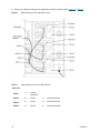
1
SNC® 6101 Installation and Maintenance Guide ADVANCED DIGITAL INFORMATION CORPORATION www.adic.com Copyright © 2003-2004 ADIC The information contained in this document is subject to change without notice. This document contains proprietary information which is protected by copyright. All rights are reserved. No part of this document may be photocopied, reproduced, or translated to another language without prior written consent of ADIC. ADIC shall not be liable for errors contained herein or for incidental or consequential damages (including lost profits) in connection with the furnishing, performance or use of this material whether based on warranty, contract, or other legal theory. All trademarks within this document are the property of their respective owners. Copyright © 2003-2004 ADIC EuropeTM All rights reserved. No part of this document may be copied or reproduced in any form or by any means, without prior written permission of ADIC Europe, ZAC des Basses Auges, 1 rue Alfred de Vigny, 78112 Fourqueux, France. ADIC Europe assumes no responsibility for any errors that may appear in this document, and retains the right to make changes to these specifications and descriptions at any time, without notice. This publication may describe designs for which patents are pending, or have been granted. By publishing this information, ADIC Europe conveys no license under any patent or any other right. ADIC Europe makes no representation or warranty with respect to the contents of this document and specifically disclaims any implied warranties of merchantability or fitness for any particular purpose. Further, ADIC Europe reserves the right to revise or change this publication without obligation on the part of ADIC Europe to notify any person or organization of such revision of change. Every effort has been made to acknowledge trademarks and their owners. Trademarked names are used solely for identification or exemplary purposes: any omissions are unintentional. ADIC is a registered trademark and ADIC Europe is a trademark of Advanced Digital Information Corporation. ADIC USA 11431 Willows Road NE Redmond, Washington 98052-4952 Tel.: 1-800-336-1233 Fax: 1-425-881-2296 Published: December 2004 ADIC Europe ZAC des Basses Auges 1, rue Alfred de Vigny 78112 Fourqueux, France Tel.: 33-0-1-30-87-53-00 Fax: 33-0-1-30-87-53-01 ADIC-Germany GmbH&Co.KG Eschenstraße 3 89558 Böhmenkirch Germany Tel: 49-0-7332-83-0 Fax: 49-0-7332-83-135 Document Number: 6-00701-03 Rev A Contents 1 Introduction 1 Intended Audience. . . . . . . . . . . . . . . . . . . . . . . . . . . . . . . . . . . . . . . . . . . . . . . . . . . . . . . . . . . . . . . . . . Associated Documents . . . . . . . . . . . . . . . . . . . . . . . . . . . . . . . . . . . . . . . . . . . . . . . . . . . . . . . . . . . . . . Explanation of Symbols and Notes . . . . . . . . . . . . . . . . . . . . . . . . . . . . . . . . . . . . . . . . . . . . . . . . . . . . . Environmental Notices and Statements . . . . . . . . . . . . . . . . . . . . . . . . . . . . . . . . . . . . . . . . . . . . . . . . . Product Recycling . . . . . . . . . . . . . . . . . . . . . . . . . . . . . . . . . . . . . . . . . . . . . . . . . . . . . . . . . . . . . . . Lithium Battery. . . . . . . . . . . . . . . . . . . . . . . . . . . . . . . . . . . . . . . . . . . . . . . . . . . . . . . . . . . . . . . . . . Laser Safety . . . . . . . . . . . . . . . . . . . . . . . . . . . . . . . . . . . . . . . . . . . . . . . . . . . . . . . . . . . . . . . . . . . Usage Restrictions . . . . . . . . . . . . . . . . . . . . . . . . . . . . . . . . . . . . . . . . . . . . . . . . . . . . . . . . . . . . . . Handling Electrostatic Discharge-Sensitive Parts . . . . . . . . . . . . . . . . . . . . . . . . . . . . . . . . . . . . . . . Getting More Information. . . . . . . . . . . . . . . . . . . . . . . . . . . . . . . . . . . . . . . . . . . . . . . . . . . . . . . . . . . . . Scalar 100 Website . . . . . . . . . . . . . . . . . . . . . . . . . . . . . . . . . . . . . . . . . . . . . . . . . . . . . . . . . . . . . . ADIC Technical Assistance Center . . . . . . . . . . . . . . . . . . . . . . . . . . . . . . . . . . . . . . . . . . . . . . . . . . 2 Description 1 1 1 2 2 2 2 2 2 3 3 3 5 Overview . . . . . . . . . . . . . . . . . . . . . . . . . . . . . . . . . . . . . . . . . . . . . . . . . . . . . . . . . . . . . . . . . . . . . . . . . 5 Configuration Support . . . . . . . . . . . . . . . . . . . . . . . . . . . . . . . . . . . . . . . . . . . . . . . . . . . . . . . . . . . . 6 Address Mapping. . . . . . . . . . . . . . . . . . . . . . . . . . . . . . . . . . . . . . . . . . . . . . . . . . . . . . . . . . . . . . . . 6 Interface Protocol Awareness . . . . . . . . . . . . . . . . . . . . . . . . . . . . . . . . . . . . . . . . . . . . . . . . . . . . . . 6 ADIC Management Console . . . . . . . . . . . . . . . . . . . . . . . . . . . . . . . . . . . . . . . . . . . . . . . . . . . . . . . 6 Access Security Capabilities . . . . . . . . . . . . . . . . . . . . . . . . . . . . . . . . . . . . . . . . . . . . . . . . . . . . . . . 7 Channel Zoning . . . . . . . . . . . . . . . . . . . . . . . . . . . . . . . . . . . . . . . . . . . . . . . . . . . . . . . . . . . . . . . . . 7 Scalar Firewall Manager . . . . . . . . . . . . . . . . . . . . . . . . . . . . . . . . . . . . . . . . . . . . . . . . . . . . . . . . . . 7 Data Mover Module . . . . . . . . . . . . . . . . . . . . . . . . . . . . . . . . . . . . . . . . . . . . . . . . . . . . . . . . . . . . . . 8 SNC 6101 Front Panel Components . . . . . . . . . . . . . . . . . . . . . . . . . . . . . . . . . . . . . . . . . . . . . . . . . . . 8 Interface Ports . . . . . . . . . . . . . . . . . . . . . . . . . . . . . . . . . . . . . . . . . . . . . . . . . . . . . . . . . . . . . . . . . . 8 LED Indicators . . . . . . . . . . . . . . . . . . . . . . . . . . . . . . . . . . . . . . . . . . . . . . . . . . . . . . . . . . . . . . . . . . 9 Specifications . . . . . . . . . . . . . . . . . . . . . . . . . . . . . . . . . . . . . . . . . . . . . . . . . . . . . . . . . . . . . . . . . . . . 10 External dimensions . . . . . . . . . . . . . . . . . . . . . . . . . . . . . . . . . . . . . . . . . . . . . . . . . . . . . . . . . . . . 10 Weight . . . . . . . . . . . . . . . . . . . . . . . . . . . . . . . . . . . . . . . . . . . . . . . . . . . . . . . . . . . . . . . . . . . . . . . 10 Power Consumption . . . . . . . . . . . . . . . . . . . . . . . . . . . . . . . . . . . . . . . . . . . . . . . . . . . . . . . . . . . . 10 Operating Environment . . . . . . . . . . . . . . . . . . . . . . . . . . . . . . . . . . . . . . . . . . . . . . . . . . . . . . . . . . 11 Supported Platforms . . . . . . . . . . . . . . . . . . . . . . . . . . . . . . . . . . . . . . . . . . . . . . . . . . . . . . . . . . . . 11 Supported Devices . . . . . . . . . . . . . . . . . . . . . . . . . . . . . . . . . . . . . . . . . . . . . . . . . . . . . . . . . . . . . 11 Compliance . . . . . . . . . . . . . . . . . . . . . . . . . . . . . . . . . . . . . . . . . . . . . . . . . . . . . . . . . . . . . . . . . . . 11 SNC 6101 User’s Guide iii 3 Installation 13 Getting Started . . . . . . . . . . . . . . . . . . . . . . . . . . . . . . . . . . . . . . . . . . . . . . . . . . . . . . . . . . . . . . . . . . . Unpacking and Inspecting . . . . . . . . . . . . . . . . . . . . . . . . . . . . . . . . . . . . . . . . . . . . . . . . . . . . . . . . . . . Pre-Installation. . . . . . . . . . . . . . . . . . . . . . . . . . . . . . . . . . . . . . . . . . . . . . . . . . . . . . . . . . . . . . . . . . . . Installing the SNC 6101 in a Scalar 100 . . . . . . . . . . . . . . . . . . . . . . . . . . . . . . . . . . . . . . . . . . . . . . . . Cabling the SNC 6101. . . . . . . . . . . . . . . . . . . . . . . . . . . . . . . . . . . . . . . . . . . . . . . . . . . . . . . . . . . . . . Configuring the SNC 6101. . . . . . . . . . . . . . . . . . . . . . . . . . . . . . . . . . . . . . . . . . . . . . . . . . . . . . . . . . . Updating SNC 6101 Firmware. . . . . . . . . . . . . . . . . . . . . . . . . . . . . . . . . . . . . . . . . . . . . . . . . . . . . . . . Installing the Host Bus Adapter Card . . . . . . . . . . . . . . . . . . . . . . . . . . . . . . . . . . . . . . . . . . . . . . . . . . Verifying SNC 6101 Operation . . . . . . . . . . . . . . . . . . . . . . . . . . . . . . . . . . . . . . . . . . . . . . . . . . . . . . . 4 Scalar Firewall Manager 29 Host Registration Service . . . . . . . . . . . . . . . . . . . . . . . . . . . . . . . . . . . . . . . . . . . . . . . . . . . . . . . . . . . Adding and Removing Hosts . . . . . . . . . . . . . . . . . . . . . . . . . . . . . . . . . . . . . . . . . . . . . . . . . . . . . . . . . Adding a Host to the SAN Configuration . . . . . . . . . . . . . . . . . . . . . . . . . . . . . . . . . . . . . . . . . . . . . Attaching a New Host to the SAN . . . . . . . . . . . . . . . . . . . . . . . . . . . . . . . . . . . . . . . . . . . . . . . . Adding a Host Before Attaching it to the SAN. . . . . . . . . . . . . . . . . . . . . . . . . . . . . . . . . . . . . . . Removing a Host from the SAN Configuration . . . . . . . . . . . . . . . . . . . . . . . . . . . . . . . . . . . . . . Combining SFM with Channel Zoning . . . . . . . . . . . . . . . . . . . . . . . . . . . . . . . . . . . . . . . . . . . . . . . . . . 5 Maintenance 30 31 31 31 31 31 32 33 Updating Firmware and Configurations . . . . . . . . . . . . . . . . . . . . . . . . . . . . . . . . . . . . . . . . . . . . . . . . . Connecting to the SNC 6101 using the Service Port. . . . . . . . . . . . . . . . . . . . . . . . . . . . . . . . . . . . Verifying the Terminal Connection . . . . . . . . . . . . . . . . . . . . . . . . . . . . . . . . . . . . . . . . . . . . . . . Connecting to the SNC 6101 using Telnet . . . . . . . . . . . . . . . . . . . . . . . . . . . . . . . . . . . . . . . . . . . Configuring the SNC 6101 for Telnet Access . . . . . . . . . . . . . . . . . . . . . . . . . . . . . . . . . . . . . . . Creating User Accounts . . . . . . . . . . . . . . . . . . . . . . . . . . . . . . . . . . . . . . . . . . . . . . . . . . . . . . . Unlocking the Shell . . . . . . . . . . . . . . . . . . . . . . . . . . . . . . . . . . . . . . . . . . . . . . . . . . . . . . . . . . . Using Telnet . . . . . . . . . . . . . . . . . . . . . . . . . . . . . . . . . . . . . . . . . . . . . . . . . . . . . . . . . . . . . . . . Removal and Replacement Procedures . . . . . . . . . . . . . . . . . . . . . . . . . . . . . . . . . . . . . . . . . . . . . . . . Handling Electrostatic Discharge-Sensitive Parts . . . . . . . . . . . . . . . . . . . . . . . . . . . . . . . . . . . . . . Removing and Replacing the SFP . . . . . . . . . . . . . . . . . . . . . . . . . . . . . . . . . . . . . . . . . . . . . . . . . Removing the SFP . . . . . . . . . . . . . . . . . . . . . . . . . . . . . . . . . . . . . . . . . . . . . . . . . . . . . . . . . . . Replacing the SFP . . . . . . . . . . . . . . . . . . . . . . . . . . . . . . . . . . . . . . . . . . . . . . . . . . . . . . . . . . . Removing and Replacing the SNC 6101 . . . . . . . . . . . . . . . . . . . . . . . . . . . . . . . . . . . . . . . . . . . . . Replacing the SNC 6101. . . . . . . . . . . . . . . . . . . . . . . . . . . . . . . . . . . . . . . . . . . . . . . . . . . . . . . Changing the WWN. . . . . . . . . . . . . . . . . . . . . . . . . . . . . . . . . . . . . . . . . . . . . . . . . . . . . . . . . . . . . . . . Before Changing the WWN on a Replacement SNC 6101 . . . . . . . . . . . . . . . . . . . . . . . . . . . . . . . Changing the WWN for all FC Ports . . . . . . . . . . . . . . . . . . . . . . . . . . . . . . . . . . . . . . . . . . . . . . . . Changing a WWN for one FC port. . . . . . . . . . . . . . . . . . . . . . . . . . . . . . . . . . . . . . . . . . . . . . . . . . Clearing Changes to the WWN for all FC ports . . . . . . . . . . . . . . . . . . . . . . . . . . . . . . . . . . . . . . . . Clearing Changes to the WWN for one FC Port . . . . . . . . . . . . . . . . . . . . . . . . . . . . . . . . . . . . . . . Final Diagnostic Tests . . . . . . . . . . . . . . . . . . . . . . . . . . . . . . . . . . . . . . . . . . . . . . . . . . . . . . . . . . . . . . Final Test Preparation . . . . . . . . . . . . . . . . . . . . . . . . . . . . . . . . . . . . . . . . . . . . . . . . . . . . . . . . . . . Fibre Channel Tests . . . . . . . . . . . . . . . . . . . . . . . . . . . . . . . . . . . . . . . . . . . . . . . . . . . . . . . . . . . . Ethernet Test . . . . . . . . . . . . . . . . . . . . . . . . . . . . . . . . . . . . . . . . . . . . . . . . . . . . . . . . . . . . . . . . . . Network Setup for the SNC 6101 . . . . . . . . . . . . . . . . . . . . . . . . . . . . . . . . . . . . . . . . . . . . . . . . . . . . . Updating the SNC 6101. . . . . . . . . . . . . . . . . . . . . . . . . . . . . . . . . . . . . . . . . . . . . . . . . . . . . . . . . . . . . Post-Repair Checklist . . . . . . . . . . . . . . . . . . . . . . . . . . . . . . . . . . . . . . . . . . . . . . . . . . . . . . . . . . . . . . iv 13 14 15 16 17 21 25 26 28 33 33 34 34 34 34 34 35 35 35 36 36 36 36 37 37 37 38 39 40 40 41 41 41 42 42 42 43 Introduction This manual provides information and instructions that support the installation and operation of the Storage Networking Controller (SNC) 6101. Intended Audience This guide is intended for operators, administrators, and maintenance personnel who interact with the SNC 6101 hardware. Associated Documents The following documents are associated with this guide: • Scalar 100 User’s Guide (6-00667-xx) • ADIC Management Console User’s Guide (6-00064-xx) • SNC Firmware 4 User’s Guide (6-00676-xx) Explanation of Symbols and Notes The following symbols appear throughout this document to highlight important information. Note Indicates important information that helps you make better use of your system. CAUTION Indicates a situation that may cause possible damage to equipment, loss of data, or interference with other equipment. WARNING INDICATES A POTENTIALLY HAZARDOUS SITUATION WHICH, IF NOT AVOIDED, COULD RESULT IN DEATH OR BODILY INJURY. SNC 6101 User’s Guide 1 Environmental Notices and Statements Environmental notices and statements that relate to the SNC 6101 include the following topics: Product Recycling This unit contains recyclable materials that must be recycled according to local regulations wherever processing sites are available. Lithium Battery This unit may contain a Lithium battery. WARNING RISK OF FIRE, EXPLOSION, OR BURNS. NEVER SHORT CIRCUIT, CRUSH, HEAT ABOVE 100 ° C, INCINERATE, OR DISASSEMBLE A LITHIUM BATTERY. Laser Safety This unit contains either a single-mode or multi-mode transceiver, which is a Class 1 laser product. The transceiver complies with IEC 825-1 and FDA 21 CFR 1040.10 and 1040.11. This transceiver must be operated under recommended operating conditions. Usage Restrictions The optical ports on your SNC 6101 must be terminated with either the optical connectors on a Fiber Channel cable or a dust plug. Handling Electrostatic Discharge-Sensitive Parts You must follow established industry practices when handling Electrostatic Discharge (ESD) Sensitive Parts. 2 • Keep the ESD-sensitive part in a static-protective bag until you are ready to install the part into the machine. • Make the fewest possible movements with your body to prevent an increase of static electricity from clothing, fibers, carpets, and furniture. • If instructed to do so, turn off the machine power before you remove ESD-sensitive parts. • Just before touching the ESD-sensitive part, discharge any static buildup in your body by first touching the metal frame or cover of the equipment. If possible, keep one hand on the frame when you install or remove an ESD-sensitive part. • For best protection, wear an ESD wrist strap. • Do not place any ESD-sensitive parts on the machine cover or on a metal table because large metal objects can become discharge paths if not grounded. If you must set aside an ESD-sensitive part, first place it into the ESD static-protective bag. • Prevent ESD-sensitive parts from being accidentally touched by other personnel. • If possible, keep all ESD-sensitive parts in a grounded metal case. Introduction • Be very careful when you work with ESD-sensitive parts in cold weather. Low humidity increases static electricity. Getting More Information If you want more information about your product, go to the Scalar 100 website or contact the ADIC Technical Assistance Center (ATAC). Scalar 100 Website For the latest information and accessories for the Scalar 100, visit the product website at www.adic.com/scalar100. ADIC Technical Assistance Center If problems cannot be solved with the aid of this document or if training is desired, contact the ADIC Technical Assistance Center (ATAC). In the USA: 800-827-3822 In Europe and Japan: 00-800-9999-3822 For other contact numbers: www.adic.com/contact To open a Service Request online: www.adic.com/techsup SNC 6101 User’s Guide 3 4 Introduction Description This chapter provides a basic overview of the SNC 6101. It describes its main features, illustrates a typical installation in a Scalar 100, identifies all user components available on its front panel, and lists important mechanical and electrical specifications. Overview An integrated SNC 6101 enables Scalar 100 customers to use and manage their library in a storage area network (SAN). When configured as a storage networking library, the Scalar 100 delivers the following functionality: • The ability to create separate data paths between heterogeneous hosts’ library components (drives and/or media changer) using Scalar Firewall Manager (SFM). SFM allows the zoning of resources so that hosts are restricted to seeing only storage they need. This endpoint security is standard in ADIC storage networking libraries and is OS, HBA, and switch independent. Heterogeneous support also enables multiple hosts with varying operating systems and backup applications to access the same library. • End-to-end path verification between the library and open system host interfaces enables administrators to discover and remedy path failures before the library is needed for backup applications. • Drive performance optimization to keep drives streaming by pre-fetching data and overlapping commands by means of an ADIC patent-pending technique. • Serverless backup by means of an integrated Data Mover Module. SNC 6101 User’s Guide 5 One possible configuration of the of the SNC 6101 is illustrated below. Configuration Support The SNC 6101 provides two Fibre Channel (FC) interfaces. These FC interfaces are configured with small form factor pluggable transceiver (SFP) modules. In addition, the SNC 6101 provides four Ultra320 SCSI interfaces as illustrated in Figure 1 on page 8. These Ultra320 interfaces are capable of both SE and LVD signaling. Address Mapping The SNC 6101 maps addresses across and between these different interfaces and preserves the persistency of the address maps across power ups of systems, devices, and Scalar 100. Interface Protocol Awareness The SNC 6101 processes SCSI-3 and SCSI-2 protocols for disk, tape, and tape medium changer devices. It can report the host and devices that are attached to its interfaces. The SNC 6101 has the capability to manage the access security between end points on the FC interface and the SCSI channels. ADIC Management Console The ADIC Management Console (AMC) offers remote, centralized management of Scalar storage networking libraries. Features of the AMC include: 6 • Management and monitoring of multiple Scalar libraries at the same time • Customizable, graphical view of ADIC libraries Description • Policy-based event logging and e-mail notification • Device-level diagnostics, reporting, and configuration All of these functions are embedded into a point and click interface designed to simplify management. The AMC receives information from Scalar storage networking libraries using the industry standard SNMP protocol. Because ADIC uses an industry standard protocol, information can be directed from ADIC libraries to framework applications. These framework applications can use SNMP Traps to generate reports and pager alerts as part of an enterprise management program. For more information, refer to the ADIC Management Console User’s Guide. Access Security Capabilities The SNC is aware of the hosts and devices that are attached to its interfaces and it provides access security between hosts and devices. Access security between different hosts and devices is a requirement for multiinitiator SAN solutions. Using the ADIC Management Console you can partition the SAN for different levels of access and performance. The SNC provides two tools for managing access security: Channel Zoning and Scalar Firewall Manager. Depending upon the unit you have purchased, one or both of these options will be available. Channel Zoning Channel zoning is a means of managing the access security between SAN connections and SCSI channels on a channel-by-channel basis. • Channel zoning can be used to secure access between a server and its storage; for example, segregating them from other servers and their respective storage. • The default settings allow all SAN connections to access all SCSI Channels. The channel zoning capability is always available to users of the SNC 6101. For more information, refer to the ADIC Management Console User’s Guide. Scalar Firewall Manager Scalar Firewall Manager (SFM) technology enables SANs with multiple users to share the same connectivity channels or pipes to access the same or different storage elements or resources. Therefore, multiple virtual private connections can be created on the same storage networking infrastructure. SFM is a Virtual Private connection or channel between a storage element and the user of that element in a Storage Area Network. Scalar Firewall Manager is a method of access security that manages the access between an initiator (user, host, system) to a target/LUN (device, disk, or tape) while protecting and preserving such permission. • SFM is completely host independent and requires no software components on the host. • SFM has no interface dependencies and supports Fibre Channel, SCSI or any other SAN interface. • SFM supports SAN connectivity/fan-out products such as switches. • SFM is independent of the storage elements and requires no change in legacy or in new storage devices. An optional automatic host registration service that sends periodic host status information to SFM is provided. For more information, refer to the ADIC Management Console User’s Guide. SNC 6101 User’s Guide 7 Data Mover Module The SNC can move data directly between the storage devices attached to it. This direct movement of data can be from disk to disk, disk to tape, tape to disk or tape to tape. The Data Mover Module frees-up valuable system resources on the server and substantially increases the speed of backup and restore operations. • The Data Mover Module is the engine for Server-Free backup and restore and HSM applications that support the Extended Copy Specification (ANSI T10/99-143r1). The Data Mover Module capability is always available to users of the SNC 6101. For more information, refer to the ADIC Management Console User’s Guide. SNC 6101 Front Panel Components The following section provides illustrations and descriptions of all components on the SNC 6101 front panel that are available to the Scalar 100 user. Interface Ports Refer to Figure 1 below for the names and locations of each port located on the SNC 6101 front panel. Figure 1 Front Panel Interface Ports FC ports (FC 1, FC 2) 8 Two Fibre Channel (FC) interfaces are configured with small form factor pluggable transceiver (SFP) modules. Cables should have a duplex LC connector on the SFP end and a connector appropriate to the HBA or switch port that the SNC is connected. The two SFP interfaces for SAN attachment can interoperate with both 2 Gb/s and 1 Gb/s data links. Throughput for these fiber-optic transceivers depends upon the specifics of your SAN and its components. An SFP can be hot swapped and is field replaceable. Description SCSI ports (SCSI 1, SCSI 2, SCSI 3, SCSI 4) Four Ultra-320 Low Voltage Differential/Single-Ended (LVD/ SE) SCSI channels with internal termination are available. These channels have automatic speed and width negotiation capability for wide or narrow bus widths and standard, fast, Ultra, Ultra2, Ultra3 or Ultra320 speeds. These parameters can be viewed from the ADIC Management Console. Service port (null modem) The service port is an RS-232 (DTE) connection with a 9-pin Dshell. It connects to the host serial port through a null-modem cable compatible with serial ports on personal computers. The service port allows access to a shell interface for local service and diagnostics. Ethernet ports (RJ-45 1, RJ-45 2) The two 10/100 Base-T Ethernet ports with RJ-45 connectors can be connected to a network switch or router by means of an unshielded twisted-pair Ethernet cable. The Ethernet ports comply with the IEEE 802.3 specification. At the time of this printing, Ethernet port #2 is disabled internally. LED Indicators LEDs on the SNC 6101 front panel provide status and activity indicators for the SNC 6101 and its interface devices. Figure 2 below provides the names and locations of these LED indicators. Figure 2 Front Panel LEDs FC 1 FC 2 For each FC Channel, the LED is ON when the channel is connected to a live Fibre Channel and OFF when the channel is not connected. It flashes with channel activity. SCSI 1 SCSI 2 SCSI 3 SCSI 4 For each SCSI channel, the LED will be OFF when no devices have been detected on the port and ON when a target is available. It flashes when there is activity on the channel and returns to the OFF state if the channel is reset. SNC 6101 User’s Guide 9 RJ-45 1 RJ-45 2 Each RJ-45 port provides two connection status LEDs. The green LED is ON when the cable is plugged into another active network device. It turns OFF whenever the Ethernet cable is disconnected or the device at the opposite end is powered down or disconnected. The yellow LED flashes to signify port activity. At the time of this printing, Ethernet port #2 was disabled internally. PWR The PWR (Power) LED is ON whenever the SNC 6101 has power applied. It flashes if the on-board power sensors determine that power supply voltages are out of range. ERR The ERR (Error) LED indicates a fault condition. This may be an overtemperature condition, fan stalled or other internally detected error situation. RDY The RDY (Ready) LED normally flashes when the SNC 6101 has finished booting. If the RDY LED remains ON or OFF for more than a few seconds, it indicates a problem. The RDY LED flashes 4 times per second when the SNC 6101 is running in diagnostic mode. Specifications This section lists the physical, electrical, and operational specifications for the SNC 6101. External dimensions 6.5 cm high x 30.5 cm deep x 25.4 cm wide 2.56 in. high x 12 in. deep x 10 in. wide Weight weight: 1.64 kg (3.62 lbs) Power Consumption The SNC 6101 receives all its power from the Scalar 100. Maximum power consumption is 30 watts in active mode. SCSI channel termination power is drawn from the Scalar 100 drive sleds, not the SNC 6101. Power supply status is monitored and reported to the ADIC Management Console. CAUTION 10 To ensure proper initialization of the SNC 6101, allow at least one minute between a Scalar 100 power-down and subsequent power-up. Description Operating Environment Operating Temperature: 10° C to 40° C (41° F to 113° F) Storage Temperature: –40° C to 70° C (–40° F to 158° F) Humidity: 10%-85% Operating, Non-Condensing, 5%-95% Non-operating, Non-Condensing Note To provide a safety margin and permit adequate cooling, the SNC 6101 is fitted with a 12 VDC tach-output blower. Should temperatures exceed specifications, an environmental alarm violation is sent and logged, permitting environmental causes of failure to be determined. This information is available from the ADIC Management Console. Supported Platforms The SNC is platform-independent. You can connect a host to the SNC 6101 after you have installed the appropriate host bus adapter and drivers. You can also connect host systems with different operating systems to the SNC 6101 through FC. For a current list of supported platforms, configurations, and host bus adapters, see www.adic.com. Supported Devices The SNC 6101 supports connections to the Scalar 100 tape library and supports all tape drives available for that unit. For a current list of supported devices, refer to www.adic.com. Compliance The FC interface controller is in compliance with the following standards and specifications: • Fibre Channel Arbitrated Loop (FC-AL-2) working draft, rev 6.4, August 28, 1998 • Fibre Channel Fabric Loop Attachment (FC-FLA) working draft, rev 2.7, August 12, 1997 • Fibre Channel Private Loop SCSI Direct Attach (FC-PLDA) working draft, rev 2.1, Sept. 22, 1997 • Fibre Channel Tape (FC-TAPE) profile, T11/98-124vD, rev 1.13, February 3, 1999 • Fibre Channel protocol SCSI (FCP-SCSI) • Fibre Channel internet protocol (IP) • Fibre Channel virtual interface (FC-VI) • Fibre Channel Class 3 support The SCSI interfaces are compliant with the following SCSI specifications: • ANSI T10/1071D Rev. 6, SCSI-3 Fast-20 • ANSI T10/375D Rev. 10t, SCSI-2 • ANSI T10/1142D Rev 20b, SCSI-3 Parallel Interface-2 SNC 6101 User’s Guide 11 12 Description Installation This section provides field procedures for installing and configuring the SNC 6101 for operation with the Scalar 100. At the completion of these procedures, your SNC 6101 will be: • mounted in the Scalar 100 Refer to the section To install the SNC 6101 on page 16. • correctly cabled to the Scalar 100 SCSI devices Refer to the section To connect the SCSI ports on page 17. • running the latest version of firmware Refer to the section To upgrade SNC 6101 Firmware on page 25. • configured with an IP and Gateway address and host name Refer to the section To configure the SNC 6101 on page 22. • connected to a host with a properly installed and configured HBA card using the latest drivers and firmware. Refer to the section Installing the Host Bus Adapter Card on page 26. • verified for correct operation Refer to the section Verifying SNC 6101 Operation on page 28. For detailed configuration procedures, refer to your SNC Firmware 4 User’s Guide. Getting Started The SNC 6101 installation process involves: • Unpacking and Inspecting your received components • Pre-installation preparation • Installing the SNC 6101 module in the Scalar 100 • Cabling the SNC 6101 to its interface devices • Configuring the SNC 6101 using the null modem service port • Installing and configuring an HBA card in your host • Verifying SNC 6101 operation Use the following checklist as a guide during the installation process: SNC 6101 User’s Guide 13 Table 1 Step SNC 6101 Installation Checklist Action Comments and References 1 Unpack and inspect SNC 6101 and accessories. Ensure that the SNC 6101 was received undamaged and with all accessories enclosed. Refer to Unpacking and Inspecting on page 14. 2 Assemble all items used during SNC 6101 installation process. Prior to beginning your installation, you must have acquired all the items identified in Pre-Installation on page 15. 3 Install the SNC 6101 into the Scalar 100 chassis. Refer to Installing the SNC 6101 in a Scalar 100 on page 16. 4 Cable the SNC 6101 SCSI ports to the Scalar 100 SCSI devices. For cabling the SCSI ports, refer to Cabling the SNC 6101 on page 17. 5 Configure the SNC 6101 using the service port. For configuration instructions, refer to Configuring the SNC 6101 on page 21. 6 Upgrade the SNC 6101 firmware using the Ethernet port. Firmware is upgraded using FTP (file transfer protocol) between a host and the SNC 6101. Refer to To upgrade SNC 6101 Firmware on page 25. 7 Verify SNC 6101 operation. Following SNC 6101 installation and configuration, refer to Verifying SNC 6101 Operation on page 28. 8 Install the Host Bus Adapter (HBA) card in the host. For installation of your HBA card, refer to Installing the Host Bus Adapter Card on page 26. For other HBA cards, refer to the current literature provided by the card’s manufacturer. 9 Install HBA drivers and firmware. For the latest driver and firmware installation in your HBA card, refer to Installing the Host Bus Adapter Card on page 26. 10 Connect SNC 6101 Fibre Channel port(s) to host or switch as required. Refer to Verifying SNC 6101 Operation on page 28. 11 Verify HBA operation with the SNC 6101. Following HBA installation and driver/firmware updates, refer to Verifying SNC 6101 Operation on page 28. Unpacking and Inspecting To unpack and inspect the SNC 6101 following delivery 1 Remove all items from the shipping carton. Note 14 Save the packing materials in case it is necessary to move or ship the SNC 6101 in the future. Installation 2 3 Verify that the these items are included and undamaged: • SNC 6101 module • SCSI cable assembly, HD68-VHDCI • DB9 serial crossover (null modem) cable • CD with Scalar 100 documentation and a CD with SNC 6101 documentation and software At this time, either fill out and mail the registration card or register the SNC 6101 online at www.adic.com. Pre-Installation Prior to actually beginning the installation, it is important that you have the following readily available during the installation: • SNC 6101 module with accessories (see above list) • The latest firmware downloaded from www.adic.com (download requires the user ID and password provided with SNC 6101) • All SCSI cables and terminators required to support your drive configuration. See Figure 7 on page 18 and Figure 8 on page 19. You must label both ends of each cable with drive ID and SNC connector number as you connect them. • RJ-45 Ethernet cable that connects the SNC 6101 and desktop/laptop. This is used for updating SNC 6101 firmware. See Figure 9 on page 20. • Fiber Channel cable for connecting the SNC 6101 with SAN or direct connect with the host. The SNC 6101 uses an LC high density connection. In environments where the library will attach to SC interfaces (GBIC, 1x9, etc.) ensure that SC to LC cables are available. Note • DB-9 null modem cable connecting the SNC 6101 and a desktop/laptop running a terminal emulation program (HyperTerminal). Preconfiguring terminal protocols is helpful. Refer to Configuring the SNC 6101 on page 21. • Host with the latest OS service packs installed • Latest drivers and firmware for your HBA card downloaded from your card manufacturer’s website. • Your network configuration for the SNC 6101: • Static IP address • Netmask • User-defined SNC 6101 name • Default Gateway address CAUTION Use of incorrect network parameters will cause problems on the Ethernet network. SNC 6101 User’s Guide 15 Installing the SNC 6101 in a Scalar 100 To install the SNC 6101 1 Power down your Scalar 100 and disconnect the AC power cord from the voltage source. 2 At the rear of the Scalar 100, find the bottom, left filler plate (see Figure 4). 3 Remove the filler plate by unscrewing the two thumb screws identified in Figure 4. CAUTION Save this filler plates for future use. If the SNC 6101 is removed, the empty slot must always be covered to prevent debris from entering the equipment and to enable proper air circulation for cooling. 4 Position the SNC 6101 module as shown in Figure 5 on page 17. Make certain the two RJ-45 and null modem ports are positioned at the top. 5 Align the top and bottom rails of the SNC 6101 with those on the Scalar 100 and slide the module into the chassis until it is flush. Note Figure 4 16 The mounting rails prevent the SNC 6101 from being inserted wrong side up. Scalar 100 Filler Plate Removal Installation Figure 5 6 SNC 6101 Installation Alignment Push in the two thumb screws identified in Figure 6 and hand tighten only. Figure 6 Scalar 100 with SNC 6101 Installed Cabling the SNC 6101 To connect the SCSI ports 1 Determine your system’s SCSI cable requirements by referring to Figure 7 on page 18, Figure 8 on page 19, Table 2 on page 18, and Table 3 on page 19. Note These figures illustrate the SNC 6101 with the maximum number of drives installed. If your system configuration contains fewer drives, always install drives in order, beginning at the bottom (drive 1). SNC 6101 User’s Guide 17 2 Route your cables according to the configuration scheme provided in either Figure 7 or Figure 8. Figure 7 SCSI Cabling for LTO and SDLT Drives Table 2 Cable Routing for LTO and SDLT Drives SNC 6101 ➯ Library/ terminator SCSI 2 ➯ Drive 1 ➯ Drive 2/terminator SCSI 3 ➯ Drive 3 ➯ Drive 4/terminator SCSI 4 ➯ Drive 5 ➯ Drive 6/terminator SCSI 1 18 Installation Figure 8 Note Table 3 SCSI Cabling for AIT Drives AIT libraries cannot have tape drives installed in the bottom-most or top-most drive module slots. Cable Routing for AIT Drives SNC 6101 SCSI 1 ➯ Library SCSI 2 ➯ Drives 3 & 4/terminator SCSI 3 ➯ Drives 5 & 6/terminator SCSI 4 ➯ Drives 7 & 8/terminator SNC 6101 User’s Guide ➯ Drives 1 & 2/terminator 19 Table 4 SNC 6101 SCSI Cable Types From To SCSI 1 Library SCSI 2 SCSI 3 SCSI 4 Tape drive Library Tape drive Tape drive Tape drive SCSI Cable Required Universal SCSI cable with a 68-pin high-density connector at one end and a VHDCI connector at the other. Universal SCSI cable with a 68-pin high-density connector at each end. 3 Insert terminators (high-density 68-pin) in all unused SCSI ports on the drives. 4 Double check your cabling, ensuring that cables are correctly routed and adequately secured in place. Also verify that all devices are correctly terminated. Note SCSI cabling can also be verified using the service port (null modem) on the SNC 6101 during configuration (scsiShow command). Refer to To configure the SNC 6101 on page 22. To connect the RJ-45 Ethernet cable to your SNC 6101 Note These installation procedures connect the Ethernet port used when you are updating SNC 6101 firmware. 1 Plug one end of your Ethernet cable into the RJ-45 1 port of the SNC 6101 (RJ-45 2 is disabled). Refer to “Ethernet ports” illustrated in Figure 5 on page 17. 2 Plug the other end of this cable into your Ethernet LAN. See Figure 9 for an example. Figure 9 3 20 Ethernet Cabling for Firmware Installation Provide another Ethernet cable to connect the laptop/desktop to your Ethernet switch. Installation Configuring the SNC 6101 You can configure the SNC 6101 as soon as you have installed it in the Scalar 100 and all appropriate cables are in place. Configuration defines these values for the SNC 6101: • IP address and subnet mask • gateway address • host name Note Configuration requires that you access the SNC 6101 command line interface by connecting the service port (null modem) on the SNC 6101 to an RS-232 DTE terminal or desktop/laptop computer that is running terminal emulation software. Most operating systems offer either Windows HyperTerminal or another default terminal emulation program. The following installation procedures use HyperTerminal as a sample program. To cable the service port to your laptop/desktop computer 1 Find the null modem cable supplied with your SNC 6101 (Refer to Unpacking and Inspecting on page 14). 2 Connect one end of the cable to the DB9 connector on the SNC 6101 that is labeled “null modem.” See Figure 1 on page 8 for the location. 3 Connect the opposite end of this cable to an available COM port on your laptop/desktop. Note Procedures for configuring your laptop/desktop as a service terminal are provided in Configuring the SNC 6101 on page 21. To configure HyperTerminal for operation as a service terminal Note 1 Configuration commands using the service port are available in the SNC Firmware 4 User’s Guide. Connect a laptop/desktop computer to the SNC 6101 null modem port with the null modem serial cable provided. See Figure 10. Figure 10 Service Port Connection to a Terminal Device SNC 6101 User’s Guide 21 2 On your computer, double-click the HyperTerminal icon (Start> Program> Accessories> Communications> HyperTerminal). 3 In the New Connection dialog box, enter SNC6101 for a name (any name will do) and click OK. 4 In the Connect To dialog box for the Connect using field, select the COM port your computer will be using (COM1, for example) and click OK. 5 In the COM Properties dialog box, select these values: Bits per second 19200 Data bits 8 Parity None Stop bits 1 Flow control None Emulation ANSI Note 6 Refer to your HyperTerminal documentation for any additional information on how to configure and run HyperTerminal. Click OK. To configure the SNC 6101 1 Power up the Scalar 100 and wait until the startup initialization process completes. Within a few minutes, the RDY LED on the SNC 6101 will start flashing once per second and the Done executing startup script message will appear on your service terminal. CAUTION 2 At the service terminal, initialize the SNC 6101 by typing initializeBox. Note CAUTION 22 To ensure proper initialization of the SNC 6101, allow at least one minute between a Scalar 100 power-down and subsequent power-up. SNC 6101 commands are case sensitive. Always enter capital and lower case characters as indicated. Use initializeBox only for a new or a replacement SNC 6101. This command resets the fibre and SCSI channels, clears the device map and the event log, and disables all enabled features. Installation 3 After entering the initializeBox command, enable the following SNC 6101 features: a. Data Mover sncFeatureEnable "enable" b. Scalar Firewall Manager sfmFeaturEnable "enable" Note 4 If the value = 1 = 0x1 message is displayed following a feature enable command, the license is installed and the feature already enabled. If a value = -1 is returned, the current license does not support that feature. Use the command licenseShow for a list of features currently licensed for your SNC 6101. Refer to your SNC Firmware 4 User’s Guide for additional information about these commands. If the Scalar Firewall Module/Virtual Private SAN or Data Mover are not listed, contact your ADIC representative for a new license key. Verify your cable connections from the SNC 6101 to SCSI devices by typing scsiShow. A typical response would be: ======================================== Ultra2/3 SCSI Initiator Channel 1: 1030 - 0x10f77000 HostId=7 AltId=Auto ID LUN Vendor Product Rev | Min Sync Period / Offset Width --------------------------------------|--------------------------------0 0 IBM SCALAR 100 2.86 | 0 - Unknown Transfer Rate / 0 1 0 IBM ULTRIUM-TD2 3434 | 9 - Ultra160 / 31 16 S W ======================================== Ultra2/3 SCSI Initiator Channel 2: 1030 - 0x10f5d000 HostId=7 AltId=Auto ID LUN Vendor Product Rev | Min Sync Period / Offset Width --------------------------------------|--------------------------------2 0 IBM ULTRIUM-TD2 3434 | 9 - Ultra160 / 31 16 S W 3 0 IBM ULTRIUM-TD2 3434 | 9 - Ultra160 / 31 16 S W ======================================== Ultra2/3 SCSI Initiator Channel 3: 1030 - 0x10fab000 HostId=7 AltId=Auto ID LUN Vendor Product Rev | Min Sync Period / Offset Width --------------------------------------|--------------------------------4 0 IBM ULTRIUM-TD2 3434 | 9 - Ultra160 / 31 16 S W 5 0 IBM ULTRIUM-TD2 3434 | 9 - Ultra160 / 31 16 S W ======================================== Ultra2/3 SCSI Initiator Channel 4: 1030 - 0x10f91000 HostId=7 AltId=Auto ID LUN Vendor Product Rev | Min Sync Period / Offset Width --------------------------------------|--------------------------------8 0 IBM ULTRIUM-TD2 333K | 9 - Ultra160 / 31 16 S W ======================================== where • SCSI Initiator Channel identifies each of the four SCSI ports on the SNC 6101 (SCSI 1 - SCSI 4) • ID is the SCSI address of the device connected to that port • Product identifies the device located at that address SNC 6101 User’s Guide 23 5 Match your actual SCSI connections with the data provided from scsiShow, ensuring that connections are correct and that all devices are present. Note 6 ID “0” is assigned to the library controller; IDs “1” through “5” and “8” through “15” (as needed) are assigned to the tape drives. Drive “1” always begins as the bottom drive. See Figure 7 and Figure 8. If a device fails to appear, verify the installation of all your cable connections and terminators. Set the IP address for the SNC 6101 using the following command: ethAddrSet "ip_address","subnet_mask" where “ip_address“ and “subnet_mask“ are replaced with actual values, for example: ethAddrSet "192.168.1.2","225.225.225.0" 7 Verify that your IP address was entered correctly by typing ethAddrGet. A typical response would be: IP Address set to 192.168.1.2:fffff800 where “192.168.1.2“ is the address just assigned, and “fffff800“ is the subnet mask displayed in hexadecimal. 8 Set the gateway address for the SNC 6101 using the following command: gateAddrSet "default_gateway_ip" where “default_gateway_ip“ is replaced with the default gateway IP address, for example: 192.168.1.1 9 Verify that your Gateway address was correctly entered by typing gateAddrGet. A typical response would be: Gateway Address set to 192.168.1.1 10 Set your host name using the following command: hostNameSet "name" where “name“ is replaced with the name you would like displayed in the ADIC Management Console. Note The default network name is the serial number of the unit. The host name always appears in the service terminal’s prompt. For easy recognition, you should provide a name that readily identifies itself with the name assigned to the library. 11 Verify that this host name now appears in the command line prompt. For example, if you entered “SNC6101” as the “name”, the prompt should read: SNC6101> 12 Set the date and time. Note You can set the real time clock either manually or with a timeserver. Refer to the procedures in your SNC Firmware 4 User’s Guide to set the clock using a timeserver. Set the date and time manually using the following command: rtcDateSet [year],[month],[day],[day of week],[hour],[minutes],[seconds] For example, to set the date for Thursday January 8, 2004, 1:08 PM, enter: 24 Installation SNC > rtcDateSet 2004,1,8,2,13,8,0 Note Use a 24-hour clock and Greenwich Mean Time when setting the RTC. Note A digit from 1-7 must be entered for the [dayofweek] parameter, but it does not matter what you enter, since the command will automatically correct it if it is wrong. 13 Use the dateSetFromRTC command to set the real time clock on the SNC as the source of date display. SNC > dateSetFromRTC value = 0 = 0x0 SNC > 14 Use the tzSet command to set the timezone. EST, used in the example, stands for Eastern Standard Time. SNC> tzSet "EST" TZ Set TIMEZONE = EST:EDT:300:040202:101502 value = 0 = 0x0 SNC > 15 Use the date command to confirm. SNC > date SNC > THU JAN 08 13:10:06 2004 SNC> > value = 0 = 0x0 Note The time will be one hour off while daylight savings time is in effect unless you reset the RTC during that period. 16 Rebuild the SNC 6101 database and initiate a reboot by typing: mapRebuildDatabase Updating SNC 6101 Firmware The SNC 6101 should always contain the latest firmware from ADIC. Use the service port to identify the installed firmware version by typing version. Check www.adic.com to determine if a newer version is available. If an upgrade is available, download the newer version (user name and password required) and follow these procedures: To upgrade SNC 6101 Firmware Note 1 Firmware can be updated either through the service port using the rz command to initiate a Zmodem file transfer session with HyperTerminal, or through the SNC 6101 Ethernet port using file transfer protocol (FTP). The following procedure uses FTP as an example. Ensure that the SNC 6101 and its host computer are connected to the network as illustrated in Figure 9 on page 20. SNC 6101 User’s Guide 25 2 Copy the downloaded firmware file to the root directory of drive C and extract it from the self-extracting executable zip file. Note You can use any location, but for simplicity in the FTP process use the root of drive C. 3 Open the command line window on the host. 4 At the command line prompt, use ping to verify your Ethernet connection to the SNC 6101: ping [SN6101 IP address] where [SN6101 IP address] is the assigned IP address for your SNC 6101, for example: ping 192.168.1.2 Note 5 If ping fails to recognize the SNC 6101 IP address, check your network cable connections and verify all SNC 6101 network properties: IP address, subnet mask, and gateway address. Log on to the SNC 6101: ftp [SN6101 IP address] where [SN6101 IP address] is replaced with the assigned IP address for your SNC 6101 (for example, 192.168.1.2). 6 When prompted, enter a user name and password. Default values are “admin” for user name and “password” for password. Note When you initially log on, the prompt appears in the root directory of your C drive, which is where you may have copied the file containing the updated firmware version (see Step 2 above). If the file is located elsewhere on your drive, move to that location using the lcd command. 7 Switch to the binary mode by typing binary. 8 Move the firmware file to the SNC 6101: put [firmware file name] /fwl/fw where [firmware file name] is replaced with the actual file name of the firmware update (for example, v042208.bin), and /fwl/fw points to where the firmware file will be copied in the SNC 6101. Note 9 Once the file transfer is completed, the firmware update begins automatically. Always reboot the SNC 6101 after a firmware update is completed. Installing the Host Bus Adapter Card 1 26 Follow the instructions provided with your HBA card to install it in the host computer. Installation HBA cards contain sensitive electronic components easily damaged by an electrostatic discharge (ESD). To prevent ESD damage while installing your card, maintain frequent contact with any grounded metal surface. Use of a grounding wrist strap is highly recommended. Handle the card carefully at all times, preferably by the edges. Avoid touching electronic components and keep the card in the original packaging until ready for installation. CAUTION 2 Access the HBA card’s website and download its latest driver and firmware files. 3 Install the HBA drivers in the host and update the card’s firmware according to the instructions provided with the download. 4 Configure the HBA’s FC port(s) for operation with the Scalar 100. Typical configuration values for a basic Scalar 100 to host connection would be as follows: • link speed: auto detect • port type: initiator/target • connection type: loop preferred • loop ID: auto detect • frame size: 2048 bytes • operating system: autosense/NT Configure your HBA settings to match these values. Refer to the documentation provided with your HBA card for the specific configuration procedures. To configure FC and SCSI parameters for SANs having different or more advanced requirements, refer to your ADIC Management Console User's Guide. To verify operation of the HBA Fibre Channel 1 At this time, turn off the host and ensure that the Scalar 100 is turned on. 2 Route fiber-optic cable with duplex LC connector from the SNC 6101 to the FC port on the SAN switch. If you are directly connecting the Scalar 100 to a host, route the cable directly to the host HBA. 3 Plug the FC cable into the FC 1 channel on the SNC 6101. Note For advanced configurations such as using the channel zoning feature for load balancing, it is necessary to cable both SNC 6101 Fibre Channel ports to the SAN. 4 When directly attaching the Scalar 100 to a host, plug the opposite end of the FC cable attached to the SNC 6101 into the HBA on the host. For SAN fabric environments, route a FC cable from the host HBA to the desired FC port on the SAN switch. 5 Turn on the host. 6 Open Device Manager (right-click My Computer>Manage>Device Manager). 7 Verify that the Device Manager now lists the Scalar 100 devices under “Other devices.” SNC 6101 User’s Guide 27 Verifying SNC 6101 Operation Use the following procedures to verify SNC 6101 connections and configure the FC port, SNMP traps, and e-mail alerts. Use the ADIC Management Console. For more information, refer to the ADIC Management Console User’s Guide. 1 Using the ADIC Management Console, confirm that all attached devices are displayed under each channel. 2 Verify/set configuration values for the FC Port. The speed and connectivity settings of the SNC 6101 default to auto detect and in most situations no additional configuration should be necessary. However, if the install environment requires custom settings, you must confirm the following: Speed: 1 GBps or 2 GBps (should match your LAN speed) Connection Options: Point-to-Point for switch attachment, Loop for arbitrated loop attachment, and Loop Preferred if the connection type is unknown (this mode will try a loop attachment first, followed by a point-to-point attachment) For more information about configuring advanced FC and SCSI parameters such as Loop ID and port mode, refer to the ADIC Management Console User’s Guide. CAUTION Do not set Port Mode to Initiator for this library. Setting Mode to Initiator will prevent hosts from seeing library drives and media changer. Initiator mode makes the SNC appear as a host instead of a storage device. 3 Configure all SNMP traps with the AMC to generate proactive alerts for the Scalar 100. For more information, refer to the ADIC Management Console User’s Guide. 4 Save your current configuration in case you need to restore it in the future. For more information, refer to the ADIC Management Console User's Guide. 5 Configure e-mail alerts with the AMC to generate e-mail messages when the Scalar 100 encounters a problem. For more information, refer to the ADIC Management Console User’s Guide. 28 Installation Scalar Firewall Manager Scalar Firewall Manager (SFM) is a software feature that collects all host and target information and manages the end-to-end access control in the SAN. It allows the system administrator to control access privileges between individual Host Bus Adapters (HBAs) and target devices connected to the SNC 6101 SCSI and Fibre Channels. The system administrator uses the ADIC Management Console to administrate the SFM. • SFM technology enables Storage Area Networks with multiple users to share the same connectivity channels or pipes to access the same or different storage elements or resources. Therefore, multiple virtual private connections can be created on the same Storage Networking infrastructure. • SFM is completely host independent and requires no software components on the host. An optional automatic Host Registration Service that provides periodic host status information is included. It has no interface dependencies and supports Fibre Channel, SCSI, or any other SAN interface. It is also independent of the storage elements and requires no change in legacy or in new storage devices. • SFM keeps track of Fibre Channel HBAs by their unique World Wide Name (WWN). Because Fibre Channel switches also have a WWN, SFM can see and can control access to FC switches connected to the SNC 6101. • SFM manages access for hosts connected through FC switches to the SNC 6101. The SNC 6101 supports up to 2048 LUNs across all of its interfaces. It has a virtual limit of how many hosts (HBAs or Initiators) are connected to each port. The default setting allows 64 initiators per port. Consequently, with the default setting, an SNC 6101 with its two Fibre Channel ports can support up to 128 host connections. • SFM creates and maintains a database in non-volatile memory to hold persistent information about each HBA (or Initiator) and its LUN access privileges. • When you perform a Save Configuration from the ADIC Management Console, it saves both the persistent device map and the SFM database to a file. This allows all configuration settings to be loaded onto another SNC 6101 in the event that the SNC 6101 needs to be replaced. • When SFM is enabled for the first time, it takes a “snapshot” of the existing configuration. SFM automatically assigns access between HBAs and the storage elements that they currently have access to so that an existing configuration will not be affected. Consequently, online hosts attached to an SNC 6101 will continue to retain their current access permissions to storage elements. • Any HBA (or Initiator) that is added to a SAN connection at a later time will have access only to the SNC 6101 Command and Control LUN. In this case, the system administrator must explicitly set access privileges to the desired storage element for each host connection. SNC 6101 User’s Guide 29 Host Registration Service The Host Registration Service (HRS) is a small agent installed on the hosts that access the library. HRS simplifies security configuration and allows administrators to monitor host connections to the library. To do this, HRS sends a periodic data pulse through the host’s Fibre Channel HBA to the library. The pulse consists of the host’s WWN, network name, HBA type, and HBA driver level. The SNC 6101 records this information and displays it in the AMC. This information is used to simplify configuration of the SFM embedded firewall. Instead of manually associating an HBA WWN with a specific host, you can configure the Scalar Firewall Manager with wellknown host names. HRS is also used to monitor the status of hosts connected to the library. When the SNC 6101 receives an HRS pulse from a host, the host is displayed in the AMC as “online.” If the SNC 6101 does not receive two consecutive HRS pulses, the host will be listed as “offline.” Note CAUTION The AMC view must be refreshed to see status changes for hosts. If SFM is not enabled, hosts will not appear in the AMC. The SFM database contains separate fields to store the WWN, host name, host type, connection, host status and a LUN access field that holds information about LUNs assigned to it. When the SNC 6101 is first booted, SFM initially treats all hosts as “offline” until a host sends an I/O request to the SNC 6101. SFM detects the I/O and obtains the WWN of the HBA or Initiator. If the WWN is already in the database (already registered), SFM stores the value “online” in the status field. If the WWN is not in the database, SFM adds it and stores the value “online” in the status field. SFM sets the default value for each of the other parameter fields to “unknown.” At this point, SFM has registered the HBA or Initiator but has minimal information about it. The system administrator can proceed to complete the registration by using the SNC 6101 to manually enter the “unknown” host information and assign access privileges to LUNs. Note 30 To install the Host Registration Service, please refer to your ADIC Management Console User’s Guide. Scalar Firewall Manager Once installed, the service runs automatically and does not require further system administrator interaction. From the ADIC Management Console, you can see the Fibre Channel that the host is connected to and you can tell whether the host is online or offline. For software updates, visit “Service and Support” at www.adic.com. Note You must refresh the SNC 6101 from the ADIC Management Console to see host status changes. Adding and Removing Hosts After SFM is enabled, you may want to add a Host (or Initiator) to the SAN configuration or remove it from the SAN configuration. This section describes how to add and remove hosts. Adding a Host to the SAN Configuration You can connect a new host to the SAN at any time. SFM automatically adds the new host to the database as soon as the host is attached to the SAN. If you want to attach a new host at this time, refer to Attaching a New Host to the SAN below. Otherwise, if you want to configure SFM before attaching the host, refer to Adding a Host Before Attaching it to the SAN on page 31. Attaching a New Host to the SAN When you attach a new host to the SAN, SFM automatically detects the host and adds it to the SFM database. When you connect or refresh the SNC 6101 from the ADIC Management Console, you can see the new host in the SFM Access Settings window. If the Host Registration Service is running on the host, SFM automatically obtains the host parameters. If the Host Registration Service is not running on the host, SFM only knows the WWN of the HBA. In this case, you must manually enter the other host parameters. Follow these steps to add a new host to the SAN configuration: 1 Connect the host to the SAN. 2 If you need to install the Host Registration Service, refer the ADIC Management Console User’s Guide. 3 If you need to determine LUN assignments for the devices you want to assign to the new host, refer to the ADIC Management Console User’s Guide. 4 For further information about entering host parameters, refer to the ADIC Management Console User’s Guide. 5 Refer to the ADIC Management Console User’s Guide to assign access permissions for the new host. 6 For information on enabling and configuring the Scalar Firewall Manager, refer to the ADIC Management Console User’s Guide. Adding a Host Before Attaching it to the SAN You can add a host that has not yet been attached to the SAN and configure its access permissions beforehand. For more information, refer to the “Add VPS/SFM Hosts” section of the ADIC Management Console User’s Guide. After the new host has been added you can assign its access permissions. Removing a Host from the SAN Configuration You may want to remove a host from the SFM database. SFM will prevent you from removing a host that is online. For more information, refer to the “Deleting VPS/SFM Hosts” section of the ADIC Management Console User’s Guide. SNC 6101 User’s Guide 31 Combining SFM with Channel Zoning In certain instances, it may be an advantage to combine the channel level security of channel zoning with the advanced LUN level security of Scalar Firewall Manager (SFM) to achieve a mix of load balancing and host-specific security. In this situation, channel zoning provides load balancing while SFM delivers resource security and hetergenous host support. Channel zoning enables load balancing by configuring certain SCSI channels to be accessible only across specific SAN connections. This is typically done by defining SCSI channels 1 and 2 to be accessible through FC port 1 of the SNC, and SCSI channels 3 and 4 to be accessible through FC port 2. This ensures that data traffic is split across the SNC 6101 SAN interfaces. SFM is configured as usual, but the administrator must be aware that SFM does not override channel zoning. A host must have LUN level access to a drive through SFM and be bound to the correct SNC FC port. If the host is incorrectly connected to the SNC, the combination of channel zoning and SFM may prevent the host from seeing resources. Note 32 When troubleshooting a configuration with both SFM and channel zoning enabled, the administrator must check all security settings to ensure a host can see devices. For example, SFM is configured to allow host A to have access to LUN 3, a drive on SCSI channel 3. Channel Zoning is configured for FC port 1 to access SCSI ports 1 & 2 and FC port 2 to access SCSI ports 3 & 4. For the host to properly see LUN 3, the drive on SCSI channel 3, the host must connect to FC port 2 of the SNC. Scalar Firewall Manager Maintenance This section provides procedures for the removal, replacement, and testing of the SNC 6101. Updating Firmware and Configurations Although the ADIC Management Console (AMC) is the simplest and most efficient tool for updating firmware and saving/loading configurations, the administrator can use the service terminal as an alternate method to perform these operations. For more information on using the AMC to update firmware and configuration, refer to the ADIC Management Console User’s Guide. For more information on updating firmware and configuration through the service terminal, refer to To configure the SNC 6101 on page 22. Connecting to the SNC 6101 using the Service Port The service port is an RS-232C Data Terminal Equipment (DTE) port. Its 9-pin connector is compatible with serial ports on a PC using a 9-pin to 9-pin null modem cable. Note For service port access using other equipment, such as a UNIX workstation, a different cable or an adapter may be required. Once the service terminal has been attached to the SNC 6101 service port, a terminal emulation program will be required to access the command line interface. Note Configuration commands that are available to control, manage, and service the SNC 6101 are documented in SNC Firmware 4 User’s Guide. Refer to the “Service Port Command Reference” section. Most operating systems come with HyperTerminal or some other form of terminal emulation program by default. If a terminal emulation program is not present, one should be available (or at least recommended) by your operating system provider. For instructions on cabling a PC to the SNC 6101 and setting up HyperTerminal, refer to To cable the service port to your laptop/desktop computer on page 21. SNC 6101 User’s Guide 33 Verifying the Terminal Connection When the SNC 6101 is turned on, you can see all characters typed in the terminal. The simplest test is to press Enter. The SNC responds by displaying a command prompt. SNC6101 > For additional commands that are available to control, manage, and service the SNC 6101, refer to the SNC Firmware 4 User’s Guide. When the SNC 6101 is rebooting, several messages are displayed on the service terminal. A successful boot is indicated by the last message: Done executing startup script. Connecting to the SNC 6101 using Telnet In instances where command line access to the SNC 6101 is required and local access is not permissible, it is possible to telnet into the SNC 6101. Telnet access should be reserved for remote update of the SNC 6101 clock, IP information, or collection of a support dump. For all other management tasks, the ADIC Management Console is the preferred method of updating information. CAUTION Modifications made to the SNC 6101 while using telnet are permanent. There is no Cancel key to back out of changes. Configuring the SNC 6101 for Telnet Access If you want to access the SNC 6101 command line interface through its Ethernet port using a telnet session, you need to add a user account. Note Refer Updating SNC 6101 Firmware on page 25 to learn the telnet procedures required to upgrade SNC 6101 firmware. Creating User Accounts Telnet user accounts are separate from those created in the AMC. The user name you specify must be three or more characters. The password must be eight or more characters. Each SNC 6101 maintains its own list of user accounts and passwords. To create a user, you must establish a serial connection to the SNC 6101 and enter the following command: userAdd "xxxx","yyyy" where xxxx is your user name and yyyy is your password. Create additional user accounts as necessary. Unlocking the Shell The SNC 6101 uses a command called shellLock to prevent a single telnet user from monopolizing the command line session or overriding a serial session. Run the command shellLock to allow only a single diagnostic connection (telnet or serial) to the device. When telnet connects to the SNC 6101, the shellLock value is automatically changed to '1' and the serial port is locked out. When the telnet session disconnects, the serial port can once again access to the shell. Note Even when the shell is locked, the ADIC Management Console (AMC) is able to manage the SNC 6101. Any administrator with AMC can access the unit and make changes as well, including the downloading of firmware The shellLock setting is not persistent across boots. An AMC administrator can restart the unit thereby unlocking the shell. To prevent a user from connecting with AMC, disconnect the Ethernet connection. 34 Maintenance 1 To prevent a telnet user from locking the command line shell, establish a command line connection to the SNC 6101 and enter: shellLock 1 To unlock the shell enter: shellLock 0 Using Telnet When opening a telnet connection to the SNC 6101, you must ensure that: • A valid user account and password exists • ShellLock is set to 0 • No other administrator is accessing the SNC 6101 through telnet To open a session to the SNC 6101, start telnet and enter open x.x.x.x where x.x.x.x is the IP address of the SNC 6101. You could also type telnet x.x.x.x. Once a session is opened, the connection will remain locked until the telnet session is closed or the SNC 6101 is rebooted. CAUTION Note Once a telnet session is open, no other user may administer the SNC 6101 from the command line. This includes both telnet and serial port connections. This is a function of the VxWorks operating system to prevent simultaneous updates by multiple users. Even when the shell is locked, the ADIC Management Console will be able to manage the SNC 6101. Removal and Replacement Procedures The following describes the removal and replacement procedures for the SNC 6101 in its entirety or for one or more of its SFPs. Handling Electrostatic Discharge-Sensitive Parts Ensure that you follow established industry procedures when handling Electrostatic Discharge (ESD) Sensitive Parts. • Keep the ESD-sensitive part in a static-protective bag until it’s ready to install. • Minimize body movements to prevent static electricity being generated from clothing, fibers, carpets, and furniture. • Prior to touching an ESD-sensitive part, first discharge your body by touching the metal frame or cover of the equipment. If possible, keep one hand on the frame when you install or remove an ESD-sensitive part. • Wearing an ESD wrist strap is always recommended. • Do not place any ESD-sensitive parts on the equipment cover or on a metal table. Large metal objects can become discharge paths if not grounded. • If you must set aside an ESD-sensitive part, first place it into the ESD static-protective bag. • Prevent ESD-sensitive parts from being accidentally touched by other personnel. SNC 6101 User’s Guide 35 • When possible, keep all ESD-sensitive parts in a grounded metal case. • Be very careful when you work with ESD-sensitive parts in cold weather. Low humidity increases the buildup static electricity. Removing and Replacing the SFP Follow the procedures below to remove and replace the SFP (small form factor pluggable transceiver). CAUTION Shut down the host systems to ensure that all I/O through the SNC 6101 has stopped. Removing the SFP 1 Unplug the Fibre Channel cable. 2 Press down on the SFP release button and pull it out of the channel slot. 3 Place the SFP in a static-protective bag. Replacing the SFP 1 Insert the SFP into the channel slot. 2 Remove the dust caps from the SFP. 3 Plug the Fibre Channel cables back in, ensuring the correct polarity. Removing and Replacing the SNC 6101 If a repair action is required for the SNC 6101, you should follow these replacement steps. CAUTION Shut down the host systems to ensure that all I/O through the SNC 6101 has stopped. 1 Record and save the current configuration information using the supportDump command followed by fcShowNames to collect the assigned WWNs. For more information, refer to the SNC Firmware 4 User’s Guide. 2 If you are removing a replacement unit that had its WWN (World Wide Name) changed, proceed to Changing the WWN on page 37, otherwise, proceed to Step 3. 3 Power down the Scalar 100 and disconnect its AC power cord. 4 For each cable attached to the SNC 6101: • Remove the cable. • Mark the cable to identify its location (for example, SNC number 3, SCSI channel 1). 5 Loosen the two thumbscrews on the back of the SNC 6101. 6 Remove the module from the Scalar 100. 36 Maintenance Replacing the SNC 6101 1 Remove the SNC 6101 from its protective bag. 2 Install it in the Scalar 100 according to the steps available in To install the SNC 6101 on page 16. 3 If it is not imperative for the replacement SNC 6101 to have a WWN identical to the replaced SNC 6101, proceed to the Final Diagnostic Tests on page 41. If the replacement SNC 6101 must have a WWN identical to the replaced SNC 6101, proceed to Changing the WWN. Changing the WWN Before you make any changes to the world wide names of the SNC 6101, read the following discussion in its entirety. All Fibre Channel devices are identified by world wide names (WWNs). These names uniquely identify a device on a storage area network (SAN) and are used by hosts to correctly connect to the storage networking controller (SNC) or I/O blade. WWNs are divided into two types: port names, which identify individual ports; and node names, which identify the entire unit. WWNs are formed of three critical components: • Port/Node ID—distinguishes port WWNs from node WWNs • OUI—identifies the device type, stands for organizational unique identifier • Device ID—identifies the specific device For ADIC devices, the node ID is always “10:00” and the port ID is “20:x0” where x is the port number. The OUI is “00:60:45” for the SNC 3000 and 5000 series and “00:30:8C” for the SNC 6000 series. If for any reason you incorrectly enter a WWN, the changes can be cleared and replaced with the original WWN, which is stored in the SNC. CAUTION Only trained and authorized service personnel should use these procedures. Data corruption or loss may result from the incorrect use of these procedures. Do not change the WWN of any device on the SAN before you talk to your service representative. Before Changing the WWN on a Replacement SNC 6101 1 Find your saved copy of the current (pre-replacement) configuration. Refer the SNC Firmware 4.4x Users Guide for information on saving a configuration file. 2 Use the fcShowNames command and save its output to an easily accessible location in case the SNC 6101 should ever fail. The following provides an example of the output from this command: SNC > fcShowNames ----------------------------------------------------------------Ctlr : PCI Addr : ISP : Node : Port Id : Bs Dv Fn : Type : Name : Name ----------------------------------------------------------------1 : 00 07 00 : 2300 : 1000030.8c1705eb : 20010060.451705eb 2 : 00 08 00 : 2300 : 1000030.8c1705eb : 20020060.451705eb ----------------------------------------------------------------value = 66 = 0x42 = 'B' SNC > 3 Install and cable the replacement SNC 6101. Follow the instructions provided in Cabling the SNC 6101 on page 17. SNC 6101 User’s Guide 37 4 Connect a service terminal to the service port. For the location of this port, refer to Front Panel Interface Ports on page 8 of this User’s Guide. 5 Use the scsiShow command to obtain a detailed listing of all connected SCSI devices as illustrated in To configure the SNC 6101 on page 22. If the output from the scsiShow command is not accurate, ensure that all cable connections and terminators are installed correctly and that all devices are present. Changing the WWN for all FC Ports Use the following procedure when replacing the SNC 6101 and it is critical that the replacement SNC 6101 uses the same WWN. 1 Read the section Changing the WWN on page 37. 2 Follow the instructions in Before Changing the WWN on a Replacement SNC 6101 on page 37. CAUTION 3 The WWN override functions are available only through the service port. These commands cannot be executed if attempted in a telnet session. Use the wwnGlobalSet command to establish a new base WWN. wwnGlobalSet updates both the node and port names and presents the following information: This command will change the WWN for Fibre Channel Ports. This should only be done when replacing a failed SNC.You should never operate 2 FC devices that are set to the same WWN. This may destabilize your SAN. The unit will be rebooted after the WWN change. Do you want to proceed (enter "yes" to continue): 4 Type “yes“and press ENTER. The following message appears: Enter the new WWN (or q to quit): 5 Enter all eight bytes of your new WWN. Each byte of the entry should be delimited by colons. For example: 00:00:00:30:8C:02:70:21 CAUTION wwnGlobalSet requires that the first byte be entered as "00" even if fcShowNames displays "10" in that position. CAUTION When entering the WWN, the firmware will confirm that the node ID and OUI match the existing values. This prevents you from accidentally making the SNC appear as another vendor’s device. The first five bytes of the entry are checked. If the entry is valid, you are prompted for a password. 6 Enter the password OverrideWWN and press ENTER. This causes the SNC 6101 to reboot. 38 Maintenance 7 After the SNC 6101 reboots, use fcShowNames to verify your changes. Verify that the output in the Node Name column is correct. Changing a WWN for one FC port Use the following procedure when you replace another vendor’s appliance with an SNC 6101 and it is critical that one of the replacement SNC FC ports retain the same WWN as the FC port of the replaced appliance. CAUTION Because you are changing the SNC WWNs to represent another vendor’s device, there are no checks to make certain an appropriate node or port ID or OUI are entered. Use caution. Entering inaccurate WWN information could cause communication issues. 1 Read the section Changing the WWN on page 37. 2 Follow the instructions in Before Changing the WWN on a Replacement SNC 6101 on page 37. CAUTION 3 WWN override functions are available only through the service port. These commands cannot be executed if attempted in a telnet session. From the service terminal, enter the wwnPortSet <port> command to set the WWPN and WWNN for a single FC port. wwnPortSet sets the Port and Node WWNs for a single FC port. The port number is also specified on the command line. After your entry is checked for syntax and the WWN you entered is valid, you are prompted to enter a password. Refer to the following wwnPortSet example: SNC > wwnPortSet 2 This command will change the WWN for Fibre Channel Port <2>. You will be asked to provide both the Node WWN and Port WWN for this port. You should never operate 2 FC devices that are set to the same WWN. This may destabilize your SAN. Do you want to proceed (enter "yes" to continue): yes Enter the new Node WWN (or q to quit): 10:20:30:40:50:60:70:80 Enter the new Port WWN (or q to quit): 11:21:31:41:51:61:71:81 Enter the Password: OverrideWWN If the password you enter is valid, this also causes the SNC 6101 to reboot. CAUTION Most vendors require the OUI and device ID to match between the WWPN and WWNN. Make sure these values match or device connectivity may not occur. It is possible for the SNC to have a different WWNN for each port. 4 After the SNC 6101 has rebooted, enter the fcShowNames command to verify the change. 5 Verify that the output in the Port Name column is correct. SNC 6101 User’s Guide 39 Clearing Changes to the WWN for all FC ports Use this procedure when you are removing an SNC 6101 that had its WWNs changed to match a preexisting unit. 1 Read the section Changing the WWN on page 37. 2 Follow the instructions in Before Changing the WWN on a Replacement SNC 6101 on page 37. CAUTION 3 The WWN override functions are available only through the service port. These commands cannot be executed if attempted in a telnet session. Enter the wwnGlobalClear command. The following messages are displayed: This command will restore the WWN for Fibre Channel Ports. This should only be done when there is no SNC set to this WWN. You should never operate 2 FC devices that are set to the same WWN. This may destabilize your SAN. The unit will be rebooted after the WWN change. Do you want to proceed (enter "yes" to continue): 4 Type “yes“ and press ENTER. You are prompted for the password. 5 Type the password OverrideWWN and press ENTER. This causes the SNC 6101 to reboot. 6 After the SNC 6101 has rebooted, enter the fcShowNames command to verify your changes. The output in the Node Name column of the of the fcShowNames command should no longer match the output previously saved before using the wwnGlobalClear command. Clearing Changes to the WWN for one FC Port Use this procedure when you are removing an SNC 6101 with the WWN on one port changed to match the WWN of a pre-existing unit. 1 Read the section Changing the WWN on page 37. 2 Follow the instructions in Before Changing the WWN on a Replacement SNC 6101 on page 37. CAUTION 3 The WWN override functions are available only through the service port. These commands cannot be executed if attempted in a telnet session. Enter the wwnPortClear <port> command. The following message will appear: This command will restore the WWN for Fibre Channel Port <x>. This should only be done when there is no SNC set to this WWN. You should never operate 2 FC devices that are set to the same WWN. This may destabilize your SAN. The unit will be rebooted after the WWN change. Do you want to proceed (enter "yes" to continue): 40 Maintenance 4 Type “yes” and press ENTER. You are prompted for the password. 5 Key in the password OverrideWWN and press ENTER. This causes the SNC to reboot. 6 After the SNC has rebooted, use the fcShowNames command to verify your changes. The output in the Node Name column of the of the fcShowNames command should no longer match the output previously saved before using wwnGlobalClear. Final Diagnostic Tests After a SNC 6101 has been replaced, a diagnostic check should be performed to ensure that it now operates properly. Final Test Preparation 1 Connect a service terminal to the SNC 6101. For information about how to do this, refer to To cable the service port to your laptop/desktop computer on page 21. 2 Power ON the Scalar 100 and wait until the SNC 6101 finishes booting. 3 Press the Enter key on the service terminal to display the prompt. 4 From the service terminal, enter the diagBoot command. 5 Wait until the SNC 6101 has finished booting into diagnostic mode. 6 From the service terminal, enter the showBox command. 7 Verify that the SNC 6101 accurately displays the channel information. 8 Proceed to Fibre Channel Tests on page 41 Fibre Channel Tests 1 Connect the service terminal to the service port. Instructions for doing so are provided in To cable the service port to your laptop/desktop computer on page 21. 2 Press Enter on the service terminal to display the prompt. 3 From the service terminal, enter the showBox command. For more information about this command and an example of its use, refer to the SNC Firmware 4 User’s Guide. 4 Confirm that the Fibre Channel connections are correctly displayed. 5 If the Fibre Channel connections do not display correctly in the showBox display, remove the GBIC and replace it with a known-good GBIC. Proceed to Ethernet Test. SNC 6101 User’s Guide 41 Ethernet Test Note 1 Ethernet port “2” is disabled internally. Omit testing of this port. Obtain the Ethernet network parameters for the SNC 6101. For more information, refer to To configure the SNC 6101 on page 22. 2 Attach the Ethernet loop back plug to the Ethernet port. 3 From the service terminal, enter the elTest command. 4 If the test passes, go to Step 5. 5 Remove the Ethernet loop back plug. Network Setup for the SNC 6101 The SNC 6101 must be connected to a 10/100-base-T Ethernet network for use with the ADIC Management Console software. For more information, refer to the ADIC Management Console User Guide. Configuring network parameters requires access to the SNC 6101 service port. Complete procedures for setting these values are provided in To configure the SNC 6101 on page 22. Updating the SNC 6101 1 From the service terminal, enter the normalBoot command. 2 Wait until the SNC 6101 has finished booting. 3 From the service terminal, enter the version command. 4 Write down the operating software version number. 5 Determine whether the SNC 6101 firmware version requires an update. If an update is required, download the new file or files and the associated readme file. You will install the new firmware as you complete the Post-Repair Checklist on page 43. 6 If you replaced the SNC 6101, enter the ridTag command and type the identifier. Note Use the sysVpdShow command to obtain the required identifier from the original SNC 6101. The ridTag command does not need to be used for replacement units obtained from the factory. 7 Power down the SNC 6101 and the Scalar 100. 8 Unplug the AC power cord. 9 Disconnect the RS-232 cable from the SNC 6101 service port. 10 Proceed to Post-Repair Checklist on page 43. 42 Maintenance Post-Repair Checklist To ensure a successful SNC 6101 installation, it is important that the items in this checklist be verified after you have completed the replacement process. Table 5 Step Post Replacement Checklist Actions Comments and References 1 Install the replacement SNC 6101 in the Scalar 100. Refer to Replacing the SNC 6101 on page 37. 2 Ensure that the FC hosts are turned off. If not, disconnect the FC cables now. If you cannot turn off the FC hosts you must disconnect the FC hosts before turning ON the SNC 6101. This precaution ensures that FC hosts cannot perform any I/O to the SCSI target devices prior to restoring the SNC 6101 configuration. 3 Cable a service terminal to the service port of the SNC 6101. Refer to To cable the service port to your laptop/ desktop computer on page 21 and To configure HyperTerminal for operation as a service terminal on page 21. 4 Turn on the Scalar 100. None. 5 Wait for the SNC 6101 to finish booting. Within one minute, the Ready LED should start flashing once per second and the “Done executing startup script” message should be displayed on the service terminal. 6 From the service terminal, enter the scsiShow command. Refer to the SNC Firmware 4 User’s Guide. Verify that all attached SCSI devices appear in the output report. Refer to To configure the SNC 6101 on page 22 for a sample report. 7 Modify the WWN for a replacement SNC 6101 only if it is critical that the replacement have the same WWN as the replaced SNC 6101. Refer to Changing the WWN on page 37. 8 Configure network parameters for the SNC 6101. Refer to To configure the SNC 6101 on page 22 for parameter setup procedures. 9 Perform the following: • If more current firmware is available, update the firmware. For firmware update procedures, refer to To upgrade SNC 6101 Firmware on page 25. • Load the configuration file you saved in Step 1 of Removing and Replacing the SNC 6101 on page 36. Refer to the SNC Firmware 4 User’s Guide for information on saving a configuration file. • Restart the SNC 6101. 10 Reconnect the FC cables removed in step 2, or, if you turned OFF any FC hosts, turn them back ON. SNC 6101 User’s Guide If FC1 and/or FC2 Connection Status LEDs for the attached Hosts are not ON, you may need to change the polarity of the FC cables. 43 Table 5 Step 44 Post Replacement Checklist Actions Comments and References 11 At the service terminal, enter the fcShow command to view the status of each FC interface that is installed and connected. In the output of the fcShow command, look for the Firmware State column. 12 From the service terminal, enter the fcShowDevs command to show the SCSI target devices that are connected as seen by the Fibre Channel interface. Check to see that all SCSI target devices are seen by each FC interface. 13 Verify that all (or the designated) target devices are available to the Host systems. If the designated devices are NOT available, reboot the Host and check again. 14 Use the fcShowNames command and save the configuration values at a location easily accessed if the SNC 6101 fails. For more information on saving the configuration, refer to the ADIC Management Console User Guide. 15 Disconnect the RS-232 cable from the and from the service terminal. None. 16 End of repair. Maintenance Index A access security . . . . . . . . . . . . . . . . . . . . . . . . . . .7 accessories, SNC 6101 . . . . . . . . . . . . . . . . . . .15 address mapping . . . . . . . . . . . . . . . . . . . . . . 2, 6 ADIC Management Console . . . . . . . . . . . . . . . . . . 6 ADIC Management Console . . . . . . . . . . . . . . . .28 AIT drive . . . . . . . . . . . . . . . . . . . . . . . . . . . . . . .19 ATAC contacting . . . . . . . . . . . . . . . . . . . . . . . . . . . 3 training . . . . . . . . . . . . . . . . . . . . . . . . . . . . . . 3 audience . . . . . . . . . . . . . . . . . . . . . . . . . . . . . . . .1 awareness, interface protocol . . . . . . . . . . . . . 2, 6 B bag, static-protective . . . . . . . . . . . . . . . . . . 2, 35 battery, lithium . . . . . . . . . . . . . . . . . . . . . . . . . . .2 binary . . . . . . . . . . . . . . . . . . . . . . . . . . . . . . . . .26 blower, tach-output . . . . . . . . . . . . . . . . . . . . . . .11 C cable Ethernet . . . . . . . . . . . . . . . . . . . . . . . . . . . . 20 fibre . . . . . . . . . . . . . . . . . . . . . . . . . . . . . . . 27 LC . . . . . . . . . . . . . . . . . . . . . . . . . . . . . . . . 15 null modem . . . . . . . . . . . . . . . . . . . . . . . . . 21 SC . . . . . . . . . . . . . . . . . . . . . . . . . . . . . . . . 15 SCSI . . . . . . . . . . . . . . . . . . . . . . . . . . . . . . 20 cabling SCSI . . . . . . . . . . . . . . . . . . . . . . . . . . . . . . 17 CD, documentation . . . . . . . . . . . . . . . . . . . . . . .15 channel zoning . . . . . . . . . . . . . . . . . . . . . . . 7, 32 COM properties HyperTerminal . . . . . . . . . . . . . . . . . . . . . . . 22 command binary . . . . . . . . . . . . . . . . . . . . . . . . . . . . . . 26 dateSetFromRTC . . . . . . . . . . . . . . . . . . . . 25 diagBoot . . . . . . . . . . . . . . . . . . . . . . . . . . . 41 ethAddrGet . . . . . . . . . . . . . . . . . . . . . . . . . 24 ethAddrSet . . . . . . . . . . . . . . . . . . . . . . . . . 24 fcShowNames . . . . . . . . . . . . . . . . . . . . . . . 36 SNC 6101 User’s Guide gateAddrGet . . . . . . . . . . . . . . . . . . . . . . . . . 24 gateAddrSet . . . . . . . . . . . . . . . . . . . . . . . . . 24 hostNameSet . . . . . . . . . . . . . . . . . . . . . . . . 24 initializeBox . . . . . . . . . . . . . . . . . . . . . . . . . .22 mapRebuildDatabase . . . . . . . . . . . . . . . . . . 25 normalBoot . . . . . . . . . . . . . . . . . . . . . . . . . .42 ping . . . . . . . . . . . . . . . . . . . . . . . . . . . . . . . . 26 put . . . . . . . . . . . . . . . . . . . . . . . . . . . . . . . . . 26 ridTag . . . . . . . . . . . . . . . . . . . . . . . . . . . . . . 42 rtcDateSet . . . . . . . . . . . . . . . . . . . . . . . . . . . 24 scsiShow . . . . . . . . . . . . . . . . . . . . . . . . .20, 23 showBox . . . . . . . . . . . . . . . . . . . . . . . . . . . . 41 userAdd . . . . . . . . . . . . . . . . . . . . . . . . . . . . 34 version . . . . . . . . . . . . . . . . . . . . . . . . . . . . . 42 command line interface . . . . . . . . . . . . . . . . . . . 21 compliance . . . . . . . . . . . . . . . . . . . . . . . . . . . . . 11 components, front panel . . . . . . . . . . . . . . . . 8, 10 configuration, support . . . . . . . . . . . . . . . . . . . . . 6 configuring HyperTerminal . . . . . . . . . . . . . . . . . . . . . . . 21 SNC 6101 . . . . . . . . . . . . . . . . . . . . . . . . . . . 21 connector, VHDCI . . . . . . . . . . . . . . . . . . . . . . . 20 console, ADIC Management . . . . . . . . . . . . . . . . 6 consumption, power . . . . . . . . . . . . . . . . . . . . . . 10 D Data Mover Module . . . . . . . . . . . . . . . . . . . . . 5, 8 dateSetFromRTC . . . . . . . . . . . . . . . . . . . . . . . . 25 description, SNC 6101 . . . . . . . . . . . . . . . . . . . . . 5 diagBoot . . . . . . . . . . . . . . . . . . . . . . . . . . . . . . . 41 diagnostic tests . . . . . . . . . . . . . . . . . . . . . . . . . 41 dimensions . . . . . . . . . . . . . . . . . . . . . . . . . . . . . 10 document organization . . . . . . . . . . . . . . . . . . . . . . . . . . 5 documentation . . . . . . . . . . . . . . . . . . . . . . . . . . 15 documents, associated . . . . . . . . . . . . . . . . . . . . 1 drives AIT . . . . . . . . . . . . . . . . . . . . . . . . . . . . . . . .19 dust plug, optical connector . . . . . . . . . . . . . . . . . 2 E e-mail alerts . . . . . . . . . . . . . . . . . . . . . . . . . . . . 28 45 environment, operating humidity . . . . . . . . . . . . . . . . . . . . . . . . . . . . 11 environmental notices . . . . . . . . . . . . . . . . . . . . . .2 ERR LED . . . . . . . . . . . . . . . . . . . . . . . . . . . . . .10 ESD caution . . . . . . . . . . . . . . . . . . . . . . . . . . . . . 27 handling parts . . . . . . . . . . . . . . . . . . . . . . . 35 ethAddrGet . . . . . . . . . . . . . . . . . . . . . . . . . . . . .24 ethAddrSet . . . . . . . . . . . . . . . . . . . . . . . . . . . . .24 Ethernet cable . . . . . . . . . . . . . . . . . . . . . . . . . . . . . . 20 port . . . . . . . . . . . . . . . . . . . . . . . . . . . . . . . . 9 test . . . . . . . . . . . . . . . . . . . . . . . . . . . . . . . . 42 example Fibre Channel configuration . . . . . . . . . . . . . 6 F FC (Fibre Channel) . . . . . . . . . . . . . . . . . . . . . .2, 6 FC port . . . . . . . . . . . . . . . . . . . . . . . . . . . . . . . . .8 fcShowNames . . . . . . . . . . . . . . . . . . . . . . . . . .36 Fibre Channel (FC) . . . . . . . . . . . . . . . . . . . . . .2, 6 Fibre Channel configuration . . . . . . . . . . . . . . . . .6 file transfer protocol (FTP) . . . . . . . . . . . . . . . . .25 filler plate, removal . . . . . . . . . . . . . . . . . . . . . . .16 firmware, SNC 6101 . . . . . . . . . . . . . . . . . . . . . .15 firmware, updating . . . . . . . . . . . . . . . . . . . . . . .33 front panel components . . . . . . . . . . . . . . . . . . . . . . . 8, 10 ports . . . . . . . . . . . . . . . . . . . . . . . . . . . . 8, 10 FTP (file transfer protocol) . . . . . . . . . . . . . . . . .25 initializeBox . . . . . . . . . . . . . . . . . . . . . . . . . . . . 22 inspecting . . . . . . . . . . . . . . . . . . . . . . . . . . . . . 14 installation . . . . . . . . . . . . . . . . . . . . . . . . . . . . . 13 interface protocol awareness . . . . . . . . . . . . . 2, 6 L laser safety . . . . . . . . . . . . . . . . . . . . . . . . . . . . . 2 LC cable . . . . . . . . . . . . . . . . . . . . . . . . . . . . . . 15 LED ERR . . . . . . . . . . . . . . . . . . . . . . . . . . . . . . . 10 indicators . . . . . . . . . . . . . . . . . . . . . . . . . . . . 9 PWR . . . . . . . . . . . . . . . . . . . . . . . . . . . . . . 10 RDY . . . . . . . . . . . . . . . . . . . . . . . . . . . . . . . 10 lithium battery . . . . . . . . . . . . . . . . . . . . . . . . . . . 2 LVD, signaling . . . . . . . . . . . . . . . . . . . . . . . . . . . 6 M Maintenance . . . . . . . . . . . . . . . . . . . . . . . . . . . 33 mapRebuildDatabase . . . . . . . . . . . . . . . . . . . . 25 modem, null . . . . . . . . . . . . . . . . . . . . . . . . . . . . 9 mounting rails, SNC 6101 . . . . . . . . . . . . . . . . . 16 N network setup . . . . . . . . . . . . . . . . . . . . . . . . . . . . . . 42 normalBoot . . . . . . . . . . . . . . . . . . . . . . . . . . . . 42 notices, environmental . . . . . . . . . . . . . . . . . . . . 2 null modem . . . . . . . . . . . . . . . . . . . . . . . . . . . . . 9 G O gateAddrGet . . . . . . . . . . . . . . . . . . . . . . . . . . . .24 gateAddrSet . . . . . . . . . . . . . . . . . . . . . . . . . . . .24 gateway address . . . . . . . . . . . . . . . . . . . . . . . .21 GBIC . . . . . . . . . . . . . . . . . . . . . . . . . . . . . . . . . .15 operating temperature . . . . . . . . . . . . . . . . . . . . 10 option, Scalar Firewall Manager (SFM) . . . . . . . 7 organization, document . . . . . . . . . . . . . . . . . . . . 5 overview, SNC 6101 1, 2, 5, 33, 35, 37, 41, 42, 43 H P HBA Fibre Channel, verification . . . . . . . . . . . . .27 help See also ATAC website . . . . . . . . . . . . . . . . . . . . . . . . . . . . . 3 host name . . . . . . . . . . . . . . . . . . . . . . . . . . . . . .21 host registration service . . . . . . . . . . . . . . . . . . .30 host, attaching . . . . . . . . . . . . . . . . . . . . . . . . . .31 hostNameSet . . . . . . . . . . . . . . . . . . . . . . . . . . .24 hosts, adding and removing . . . . . . . . . . . . . . . .31 HyperTerminal COM properties . . . . . . . . . . . . . . . . . . . . . . 22 configuring . . . . . . . . . . . . . . . . . . . . . . . . . . 21 password, default . . . . . . . . . . . . . . . . . . . . . . . 26 ping . . . . . . . . . . . . . . . . . . . . . . . . . . . . . . . . . . 26 platform, supported . . . . . . . . . . . . . . . . . . . . . . 11 port Ethernet . . . . . . . . . . . . . . . . . . . . . . . . . . . . . 9 FC . . . . . . . . . . . . . . . . . . . . . . . . . . . . . . . . . 8 SCSI . . . . . . . . . . . . . . . . . . . . . . . . . . . . . . . 9 service . . . . . . . . . . . . . . . . . . . . . . . . . . . 9, 21 power consumption . . . . . . . . . . . . . . . . . . . . . . 10 pre-installation . . . . . . . . . . . . . . . . . . . . . . . . . . 15 put . . . . . . . . . . . . . . . . . . . . . . . . . . . . . . . . . . . 26 PWR LED . . . . . . . . . . . . . . . . . . . . . . . . . . . . . 10 I R indicators, LED . . . . . . . . . . . . . . . . . . . . . . . . . . .9 RDY LED . . . . . . . . . . . . . . . . . . . . . . . . . . . . . 10 recycling, product . . . . . . . . . . . . . . . . . . . . . . . . 2 46 Index removing SFP . . . . . . . . . . . . . . . . . . . . . . . . . . . . . . . 36 SNC 6101 . . . . . . . . . . . . . . . . . . . . . . . . . . 36 replacement procedures . . . . . . . . . . . . . . . . . . .35 replacing SFP . . . . . . . . . . . . . . . . . . . . . . . . . . . . . . . 36 SNC 6101 . . . . . . . . . . . . . . . . . . . . . . . . . . 36 restrictions, usage . . . . . . . . . . . . . . . . . . . . . . . .2 ridTag . . . . . . . . . . . . . . . . . . . . . . . . . . . . . . . . .42 RS-232 . . . . . . . . . . . . . . . . . . . . . . . . . . . . . . . . .9 rtcDateSet . . . . . . . . . . . . . . . . . . . . . . . . . . . . . .24 temperature, operating . . . . . . . . . . . . . . . . . . . . 10 terminal emulation program . . . . . . . . . . . . . . . . 21 test diagnostic . . . . . . . . . . . . . . . . . . . . . . . . . . .41 Ethernet . . . . . . . . . . . . . . . . . . . . . . . . . . . .42 Fibre Channel . . . . . . . . . . . . . . . . . . . . . . . .41 thumb screws . . . . . . . . . . . . . . . . . . . . . . . . . . . 16 timeserver . . . . . . . . . . . . . . . . . . . . . . . . . . . . . 24 training ATAC . . . . . . . . . . . . . . . . . . . . . . . . . . . . . . .3 transceiver, SFP . . . . . . . . . . . . . . . . . . . . . . . . . . 6 S U safety, laser . . . . . . . . . . . . . . . . . . . . . . . . . . . . .2 SAN, storage area network . . . . . . . . . . . . . . . . .5 Scalar 100 . . . . . . . . . . . . . . . . . . . . . . . . . . . . . .5 Scalar Firewall Manager (SFM) . . . . . . . . 5, 7, 29 SCSI cables . . . . . . . . . . . . . . . . . . . . . . . . . . . . . 20 interface, Ultra3 . . . . . . . . . . . . . . . . . . . . . . . 6 port . . . . . . . . . . . . . . . . . . . . . . . . . . . . . . . . 9 SCSI specifications . . . . . . . . . . . . . . . . . . . . . . .11 scsiShow . . . . . . . . . . . . . . . . . . . . . . . . . . .20, 23 SE, signaling . . . . . . . . . . . . . . . . . . . . . . . . . . . . .6 security, access . . . . . . . . . . . . . . . . . . . . . . . . . .7 service port . . . . . . . . . . . . . . . . . . . . . . . 9, 21, 33 connection . . . . . . . . . . . . . . . . . . . . . . . . . . 21 SFM, Scalar Firewall Manager . . . . . . . . . . . . .5, 7 SFP removing . . . . . . . . . . . . . . . . . . . . . . . . . . . 36 replacing . . . . . . . . . . . . . . . . . . . . . . . . . . . 36 SFP, small form factor pluggable . . . . . . . . . . . . .6 shipping carton . . . . . . . . . . . . . . . . . . . . . . . . . .14 showBox . . . . . . . . . . . . . . . . . . . . . . . . . . . . . . .41 signaling, SE and LVD . . . . . . . . . . . . . . . . . . . . .6 small form factor pluggable (SFP) . . . . . . . . . . . .6 SNC 6101 accessories . . . . . . . . . . . . . . . . . . . . . . . . . 15 configuring . . . . . . . . . . . . . . . . . . . . . . . . . . 21 firmware . . . . . . . . . . . . . . . . . . . . . . . . . . . . 15 removing . . . . . . . . . . . . . . . . . . . . . . . . . . . 36 using telnet . . . . . . . . . . . . . . . . . . . . . . . . . 33 SNMP traps . . . . . . . . . . . . . . . . . . . . . . . . . . . .28 specifications SCSI . . . . . . . . . . . . . . . . . . . . . . . . . . . . . . 11 standards . . . . . . . . . . . . . . . . . . . . . . . . . . . 11 static-protective bag . . . . . . . . . . . . . . . . . . . .2, 35 storage area network (SAN) . . . . . . . . . . . . . . . . .5 subnet mask . . . . . . . . . . . . . . . . . . . . . . . . . . . .21 Ultra3 SCSI interface . . . . . . . . . . . . . . . . . . . . . . 6 unpacking . . . . . . . . . . . . . . . . . . . . . . . . . . . . . . 14 updating firmware, SNC 6101 firmware, updating SNC 6101 . . . . . . . . . . . .25 usage restrictions . . . . . . . . . . . . . . . . . . . . . . . . . 2 user accounts, telnet . . . . . . . . . . . . . . . . . . . . . 34 user name, default . . . . . . . . . . . . . . . . . . . . . . . 26 userAdd . . . . . . . . . . . . . . . . . . . . . . . . . . . . . . . 34 V version . . . . . . . . . . . . . . . . . . . . . . . . . . . . . . . . 42 W website library . . . . . . . . . . . . . . . . . . . . . . . . . . . . . . .3 World Wide Name (WWN) . . . . . . . . . . . . . . . . . 29 World Wide Name. See WWN wrist strap . . . . . . . . . . . . . . . . . . . . . . . . . . . .2, 35 WWN . . . . . . . . . . . . . . . . . . . . . . . . . . . . . . . . . 37 WWN (World Wide Name) . . . . . . . . . . . . . .29, 36 Z zoning, channel . . . . . . . . . . . . . . . . . . . . . . . . . . 7 T tach-output blower . . . . . . . . . . . . . . . . . . . . . . .11 telnet configuring . . . . . . . . . . . . . . . . . . . . . . . . . . 33 connecting to the SNC 6101 . . . . . . . . . . . . 33 SNC 6101 User’s Guide 47 48 Index