1
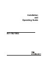
Installation
and
Operating Guide
AIT-70D/100D
Copyright Notice
Copyright ADIC 1996, 1997, 1998, 1999
The information contained in this document is subject to change without notice.
This document contains proprietary information that is protected by copyright. All rights are reserved. No
part of this document may be photocopied, reproduced or translated to another language without the prior
written consent of ADIC™.
ADIC shall not be liable for errors contained herein or for incidental or consequential damages (including
lost profits) in connection with the furnishing, performance or use of this material whether based on
warranty, contract, or other legal theory.
Printed in the U.S.A.
August 1999
Document Number 62-0110-01 Rev. D
Corporate Headquarters:
Advanced Digital Information Corporation
Shipping Address: 11431 Willows Road NE
Redmond, WA 98052
Mailing Address: P.O. Box 97057
Redmond, WA 98073-9757
Telephone: (425) 881-8004
Fax: (425) 881-2296
Worldwide Web: http://www.adic.com
ADIC Europe
ZAC des Basses Auges
1, rue Alfred de Vigny
78112 - Fourqueux, FRANCE
33.(0)1.30.87.53.00
Fax: 33.(0)1.30.87.53.01
For Customer Assistance:
In the United States and Canada, call ADIC’s Technical Assistance Center at: (800) 827-3822
In Europe, call ADIC’s Technical Assistance Center at: 00.800.9999.3822
ADIC™ and ADIC Europe™ are trademarks of Advanced Digital Information Corporation. Sony is a
registered trademark, and AIT™, MIC™ and DLC™ are trademarks of Sony Corporation. ALDC™ is a
trademark of International Business Machines Corporation. Exabyte® is a registered trademark of Exabyte
Corporation.
ii
Copyright Notice (Europe)
© Copyright 1996 ADIC Europe, 1997, 1998, 1999
All rights reserved. No part of this document may be copied or reproduced in any form or by any means,
without prior written permission of ADIC Europe, ZAC des Basses Auges, rue Alfred de Vigny 78112 Fourqueux, FRANCE.
ADIC Europe™ assumes no responsibility for any errors that may appear in this document, and retains the
right to make changes to these specifications and descriptions at any time, without notice.
This publication may describe designs for which patents are pending, or have been granted. By publishing
this information, ADIC Europe conveys no license under any patent or any other right.
ADIC Europe makes no representation or warranty with respect to the contents of this document and
specifically disclaims any implied warranties of merchantability or fitness for any particular purpose. Further
ADIC Europe reserves the right to revise or change this publication without obligation on the part of ADIC
Europe to notify any person or organization of such revision of change.
Every effort has been made to acknowledge trademarks and their owners. Trademarked names are used solely
for identification or exemplary purposes; any omissions are made unintentionally.
iii
EMI/RFI Compliance
WARNING: This equipment has been tested and found to comply with the limits for a Class B digital
device, pursuant to Part 15 of the FCC Rules. These limits are designed to provide reasonable protection
against harmful interference in a residential installation. This equipment generates, uses, and can radiate
radio frequency energy and, if not installed and used in accordance with the instructions, may cause harmful
interference to radio communications. However, there is no guarantee that interference will not occur in a
particular installation. If this equipment does cause harmful interference to radio or television reception
(which can be determined by turning the equipment off and on) the user is encouraged to try to correct the
interference by one or more of the following measures:
•
Re-orient or relocate the receiving antenna.
•
Increase the separation between the equipment and receiver.
•
Connect the equipment into an outlet on a circuit different from that to which the receiver is
connected.
•
Consult the dealer or an experienced radio/TV technician for help.
You may find the following booklet prepared by the Federal Communications Commission helpful: How to
Identify and Resolve Radio-TV Interference Problems. This booklet is available from the U.S. Government
Printing Office, Washington, DC 20402, Stock No. 004-000-00354-04.
Canada – Department of Communications
This digital apparatus does not exceed the Class B limits for radio noise emissions from digital apparatus as
set out in the interference-causing equipment standard entitled "Digital Apparatus", ICES-003 of the
Department of Communications.
Cet appareil numérique respecte les limites de bruits radioélectriques applicables aux appareils numériques
de Class B prescriptes dans la norme sur le matériel brouilleur: "Appareils Numériques", NMB-003 édictée
par le ministre des Communications.
Shielded Cables
Shielded data cables are required in order to meet FCC emissions limits. The ADIC data cable meets this
requirement. If you need a replacement cable, be sure to use an ADIC-approved shielded cable (to assure
acceptability to FCC requirements).
iv
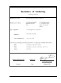
Declaration of Conformity
according to EN 45014
Manufacturer’s Name:
Advanced Digital Information Corporation
Manufacturer’s Address:
11431 Willows Road NE
Redmond, WA 98052
USA
Type of equipment:
ZAC des Basses Auges
1, rue Alfred de Vigny
78112 – Fourqueux,
France
External Digital Linear Tape Drive
Model No.:
SDX 300D/70D/100D
Year of Manufacture:
1997, 1998, 1999
conforms to the following international specifications, as required by 89/336/EEC & 92/31/EEC:
EMI:
EN 50081-1, EN-55022 Class B
EMC:
EN 50082-1, IEC 801-2, IEC 801-3, IEC 801-4
Safety:
EN 60950
Redmond, Washington USA
1-March-1997
Project Engineering Mgr.
Location
Date
Signature/Title
v
Safety
Warnings
CAUTION
RISK OF ELECTRIC SHOCK
DO NOT OPEN
This symbol should alert the
user to the presence of
"dangerous voltage" inside
the product that might cause
harm or electric shock.
CAUTION : TO REDUCE
THE RISK OF ELECTRIC
SHOCK, DO NOT REMOVE
COVER (OR BACK).
NO USER-SERVICEABLE
PARTS INSIDE. REFER
SERVICING TO QUALIFIED
SERVICE PERSONNEL.
Caution
All safety and operating instructions should be read before this product is
operated, and should be retained for future reference. This unit has been
engineered and manufactured to assure your personal safety. Improper use
can result in potential electrical shock or fire hazards. In order not to
defeat the safeguards, observe the following basic rules for its installation,
use and servicing.
vi
•
Heed Warnings - All warnings on the product and in the operating instructions should be adhered to.
•
Follow Instructions - All operating and use instructions should be followed.
•
Ventilation - The product should be situated so that its location or position does not interfere with
proper ventilation.
•
Heat - The product should be situated away from heat sources such as radiators, heat registers, furnaces,
or other heat producing appliances.
•
Power Sources - The product should be connected to a power source only of the type directed in the
operating instructions or as marked on the product.
•
Power Cord Protection - The AC line cord should be routed so that it is not likely to be walked on or
pinched by items placed upon or against it, paying particular attention to the cord at the wall receptacle,
and the point where the cord exits from the product.
•
Object and Liquid Entry - Care should be taken to insure that objects do not fall and liquids are not
spilled into the product’s enclosure through openings.
•
Servicing - The user should not attempt to service the product beyond that described in the operating
instructions. All other servicing should be referred to qualified service personnel.
Precautions
•
Do not use oil, solvents, paint thinners, gasoline, or insecticides on the unit.
•
Do not expose the unit to moisture, to temperatures higher than 60ºC (140ºF) or to extreme low
temperatures.
•
Keep the unit away from direct sunlight, strong magnetic fields, excessive dust, humidity and
electronic/electrical equipment that generates electrical noise.
•
Hold the AC power plug by the head when removing it from the AC source outlet; pulling the cord can
damage the internal wires.
•
Use the unit on a firm level surface free from vibration, and do not place anything on top of unit.
vii
Blank Page
viii
Table of Contents
Copyright Notice ...............................................................................................................................................ii
Copyright Notice (Europe) ...............................................................................................................................iii
EMI/RFI Compliance ....................................................................................................................................... iv
Safety Warnings................................................................................................................................................ vi
Precautions ...................................................................................................................................................... vii
Chapter 1 Introduction...............................................................................................................................................1
Equipment Description ......................................................................................................................................2
Switches and Indicators .....................................................................................................................................3
AIT Data Cassette..............................................................................................................................................4
Other Requirements ...........................................................................................................................................6
SCSI Host Adapter.............................................................................................................................7
Application Software .........................................................................................................................7
Chapter 2 Hardware Installation................................................................................................................................7
Unpacking and Inspecting .................................................................................................................................8
Installing the Host Adapter................................................................................................................................8
Connecting the Interface Cable..........................................................................................................................9
Connecting More than One AIT-70D/100D.....................................................................................................12
Setting the SCSI ID .........................................................................................................................................10
Check the Terminating Resistor.......................................................................................................................10
Installing the Backup Software........................................................................................................................11
Chapter 3 Operation ................................................................................................................................................13
Connecting Power and Turning On .................................................................................................................14
LCD Messages.................................................................................................................................................17
Loading the Data Cassette ...............................................................................................................................18
Removing the Data Cassette ............................................................................................................................19
Chapter 4 Maintenance............................................................................................................................................21
Cleaning the Tape Heads .................................................................................................................................22
Cleaning the Enclosure....................................................................................................................................23
Chapter 5 Troubleshooting and Diagnostics............................................................................................................25
Warning Signals ..............................................................................................................................................26
LCD Error Messages .......................................................................................................................................28
Drive LED Status.............................................................................................................................................28
Drive LED Status ............................................................................................................................................31
High Humidity.................................................................................................................................................28
When You Need Assistance ............................................................................................................................29
When Calling the ATAC .................................................................................................................................32
ix
Appendix A Specifications...................................................................................................................................... 31
Appendix B Glossary............................................................................................................................................... 33
Index........................................................................................................................................................................ 37
x
Table of Contents
Chapter
1
Introduction
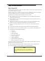
This Chapter . . .
p
provides a physical description of the switches, indicators and connectors on
the front and rear panels of the AIT-70D/100D.
p
describes other requirements (additional hardware and/or software) needed to
utilize the AIT-70D/100D.
1
Equipment Description
The ADIC 70D and 100D are SCSI-2 compatible and economical data storage devices. The 70D and 100D
both feature high-speed file access, high reliability, easy maintenance, and are designed for storage of nearline and off-line data. The 70D and 100D both feature a 2-line by 16-character LCD that is used to display
drive status, operational messages, and error messages.
The AIT-70D, equipped with the 3.5” form factor Sony AIT-1 drive (SDX-300C), provides up to 70 GB of
removable, highly reliable data storage on a low cost, pocket-sized, 170-meter data cassette (SDX1-35C,
assuming 2:1 data compression). The Fast Wide SCSI drive provides a sustained data transfer rate of over
360 MB per minute (assuming 2:1 data compression). The AIT-100D, equipped with the 3.5” form factor
AIT-2 drive (SDX-500C) provides up to 100 GB of removable, highly reliable data storage on a low cost,
pocket-sized, 230-meter data cassette (SDX2-50C, assuming 2:1data compression). The Wide Ultra SCSI
drive provides a sustained data transfer rate of over 360 MB per minute (assuming 2:1 data compression).
The AIT-1 and AIT-2 drives do not require periodic head cleaning as often as conventional tape drives. Both
of the drives constantly monitor head output to check for possible contamination. If present, the drives will
invoke a built-in Active Head Cleaner. Under extreme environmental conditions, a cleaning cassette may be
required and the drives will indicate this by displaying a Cleaning Request message on the front panel Status
LED.
The removable data cassettes (SDX1-25C, SDX1-35C, SDX2-36C, and SDX2-50C) support the Advanced
Intelligent Tape (AIT™) format. The cassettes use a new recording format, Adaptive Lossless Data
Compression (ALDC™), Memory In Cassette (MIC™) technology capabilities, and the exclusive use of
Sony’s Advanced-Metal Evaporated (AME™) media. The AME media incorporates dual cobalt magnetic
layers, the absence of binder material to prevent tape head contamination and a super-durable “diamond-like
™) protective coating for extreme durability.
The AIT-70D and AIT-100D are compatible with all operating systems and environments supporting the Fast
Wide SCSI or Wide Ultra SCSI interface, but requires either direct support of the operating system or a
suitable application program to take advantage of their features. Hosting environments that do not directly
support SCSI interfaces, like most personal computers, require the addition of a SCSI Host Adapter card. The
fast search capabilities of the Sony SDX-300C or SDX-500C drives, in conjunction with supporting
application software allows users to quickly locate and retrieve any stored file, with an average file access
time of less than 130 seconds.
Note
Exabyte (and other manufacturers) 8mm data cassettes are
not compatible with the AIT drive. Do not attempt to use 8mm
cassettes in the 70D or 100D.
®
The AIT-70D/100D drives can be connected to existing SCSI channels using a common transport protocol
like ASPI, or they can be connected to a dedicated SCSI channel. A maximum of 16 SCSI devices can be
interconnected on a single Fast Wide SCSI channel, or a Wide Ultra SCSI channel running in either High
Voltage Differential (HVD) or Low Voltage Differential (LVD) mode, not including the hosting
environment. A maximum of 8 SCSI devices can be interconnected on a single Wide Ultra SCSI channel
running in Single-ended/LVD mode (SE/LVD) providing the SCSI bus length is no longer than 1.5 meters. A
maximum of 4 SCSI devices can be interconnected on a single Wide Ultra SCSI channel running in SE/LVD
2
Introduction
mode providing the SCSI bus length is no longer than 3.0 meters. Connecting 16 AIT-70D or AIT-100D
units to a single SCSI channel will provide a maximum of 1.6 TB (average 2:1 compression) of data storage.
Switches and Indicators
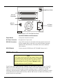
Figures 1 and 2 show the switches and indicators located on the front and rear panels of the AIT-70D. The
AIT-100D front and rear panels are similar.
Busy, Tape, Status
LEDs
Eject
Button
Figure 1. AIT-70D Front Panel
Front Panel Switches and Indicators
Busy, Tape, Status LEDs
Indicates current status of the drive, whether cartridge is loaded or not and if
there is drive activity. LEDs are also used to indicate drive errors. See
Appendix C for a listing of error messages for the AIT-70D/100D.
Eject Button
Ejects data cartridge when button is pressed. This may take up to 30 seconds
during which the drive rewinds the cartridge. The Tape LED will flash
during this time.
LCD
2-line by 16-character Liquid Crystal Display. Displays information about
drive status, operational messages, and error messages.
Introduction
3
Power Switch
SCSI I/O
Connectors
SCSI ID
Switch
AC Power
Connector
Figure 2. AIT-70D/100D Rear Panel
Rear Panel Switches and Connectors
Power Switch
Turns power to the unit on and off.
AC Power Connector
Receptacle for AC power cord.
SCSI I/O Connectors
68-pin SCSI connectors for the interface cable that connects the unit with
the host computer and/or to other devices on the SCSI channel (including
additional AIT-70D/100D units). The interface cable can be attached to
either connector.
SCSI ID Switch
Used to select the SCSI ID for the AIT-70D/100D. Factory set at 0.
AIT Data Cassette
Note
The AIT data cassette uses 8mm tape, however, Exabyte® (and
other manufacturers) 8mm data cassettes are not compatible
with the Sony AIT drive. The SDX-300C and SDX-500C drives
will sense and eject any non-AIT cassettes. Do not attempt to
use 8mm cassettes in the AIT-70D/100D.
The AIT data cassette contains 8mm tape designed to be written upon by a helical scan device. The AIT-2
SDX2-50C 230-meter data cassette can store 50 GB of data in an AIT-100D running in native mode. The
cassette can store up to 100 GB in compressed mode (assuming average 2:1 compression). The MIC
technology, which incorporates a Flash memory IC inside the data cassette, allows the architecture to capture
various system and user-related statistics directly within the MIC structure to enhance data reliability, error
prediction and success performance.
4
Introduction
Figure 3. AIT Cassette
The Write-Protect tab enables or disables the ability to write or delete files on the data cartridge. If the tab is
moved all the way to the right, the drive can write or erase data on the cartridge. If the tab is moved to the left
it protects the data cartridge so data cannot be written to or deleted from it. See Figure 4.
Figure 4. Write-Protect Tab
Introduction
5
Other Requirements
SCSI Host Adapter
If your host system does not have an integrated SCSI controller, a SCSI host adapter must be used to connect
the host computer with the AIT-70D/100D. The host adapter you choose will depend on your system
requirements and your needs. If you are not sure about your host adapter requirements, please call ADIC’s
Technical Assistance Center (ATAC) and ask for assistance.
Notes
• The AIT-70D is a Fast Wide SCSI device and is available in SE
and HVD configurations. Be sure that your host adapter is
Fast Wide SCSI capable.
• The AIT-100D is a Wide Ultra SCSI device and is available in
HVD or SE/LVD configurations. Be sure that your host
adapter is Wide Ultra SCSI capable.
• SE and HVD SCSI devices, are not compatible. Do not
attempt to connect both types of devices to the same SCSI
bus.
Caution
SE and HVD SCSI devices, are not compatible. Do not attempt to
connect both types of devices to the same SCSI bus.
Application Software
The software you use will depend upon your storage needs and the system you are using.
6
Introduction
Chapter
2
Hardware Installation
This Chapter . . .
p
explains the steps necessary to install and test your AIT-70D/100D.
p
provides a 4 symbol on each step that you should verify is correct before continuing.
7
Unpacking and Inspecting
Unpack all items from the carton. Save the packing materials in case you need to move or ship the system in
the future.
4 Unit should not have any damage.
Caution
You must ship the unit in the original or equivalent packing
materials or your warranty may be invalidated.
Installing the Host Adapter
If your host computer system does not have native SCSI capability and the host adapter you are using is not
installed, please install it. Refer to the manual that came with your host adapter for specific directions.
Notes
• The AIT-70D is a Fast Wide SCSI device and is available in SE
and HVD configurations. Be sure that your host adapter is
Fast Wide SCSI capable.
• The AIT-100D is a Wide Ultra SCSI device and is available in
HVD or SE/LVD configurations. Be sure that your host
adapter is Wide Ultra SCSI capable.
• SE and HVD SCSI devices, are not compatible. Do not
attempt to connect both types of devices to the same SCSI
bus.
Caution
SE and HVD SCSI devices, are not compatible. Do not attempt to
connect both types of devices to the same SCSI bus.
When the host adapter card is installed return to this point of this manual.
8
Hardware Installation
Connecting the Interface Cable
Note
The jack screws at both ends of the SCSI interface cable must
be securely fastened to insure that the AIT-70D/100D
communicates properly with the host computer.
Attach a shielded interface cable between the host adapter and your AIT-70D/100D. The kind of cable you
will need depends on the kind of SCSI bus connector on your host adapter. The AIT-70D/100D has a 68contact, shielded, high-density SCSI device connector.
4 Make sure that the SCSI cable between the host adapter and the AIT-70D/100D is secure and the
connections are fastened correctly.
Connecting More than One AIT-70D/100D
If you are connecting more than one AIT-70D/100D on the same SCSI channel, simply connect each unit to
the previous unit with an additional shielded interface cable. It doesn't matter which SCSI connector on each
AIT-70D/100D you connect the interface cable to. Figure 5 shows a sample configuration.
SCSI Cables
Terminator
Host
Computer
4
AIT-70D/100D
Units
Daisy-chained
Figure 5. 4 AIT-70D/100D Units Daisy-chained
Hardware Installation
9
Setting the SCSI ID
Depending upon your setup, operating system and number of SCSI devices on the bus, you may have to
change the SCSI address of the AIT-70D/100D. Each device on the bus must have its own unique address.
See Figure 6.
Note
The SCSI ID has been preset at the factory to 0.
SCSI ID
switch
AIT-70D/100D
Rear Panel
Figure 6. Setting the SCSI ID
The SCSI ID switch is located on the rear of the AIT-70D/100D. Using a small pointed object, depress either
the + or the - button to select the proper ID.
4 Count each device's SCSI ID in sequence 0 to 15 on each SCSI bus to confirm that no two SCSI devices
have the same ID.
Note
The SCSI Host Adapter is normally set to SCSI ID 16, so this ID
is usually not available for a device.
Check the Terminating Resistor
SCSI buses require termination at each end for proper operation. A typical external subsystem installation
would be terminated at the SCSI host adapter and at the last device in the chain.
If an external device were being used with an internal device (on the same channel), the SCSI host adapter
would be in the middle of the bus rather than at the end. In this case, the termination would be at the internal
10
Hardware Installation
device and the last drive in the external chain. The terminators on the SCSI host adapter would be removed.
See your SCSI host adapter manual for directions on removing the terminators on the board.
4 Is there a terminator installed on each end of the SCSI bus?
Note
Single-ended termination can be active or passive. ADIC
recommends using only active termination on a single-ended
bus.
Installing the Backup Software
At this point, please refer to your backup software installation guide and install the backup software.
4 After you have completed installation of your AIT-70D/100D and the backup software, you should run a
small backup/restore and compare to confirm that your unit is operating correctly. See your software
installation guide for further information.
Hardware Installation
11
Blank Page
12
Hardware Installation
Chapter
3
Operation
This Chapter . . .
p
explains how to operate the AIT-70D/100D.
13
Connecting Power and Turning On
p
Plug the power cord into the back of the AIT-70D/100D.
p
Plug the power cord from the AIT-70D/100D into a GROUNDED electrical outlet.
p
Plug the power cord from your host system into the same GROUNDED electrical circuit if possible.
Computers and peripherals should always share the same grounds.
p
Turn on the power to your host system.
Note
Turning on the host computer first ensures that the SCSI bus
terminators stabilize the bus signals before the AIT-70D/100D
is turned on.
p
Turn the AIT-70D/100D power on.
4 If your external SCSI bus terminator has a Term Power LED it should also be illuminated.
4 The AIT-70D/100D LCD will light up.
14
p
All three front panel LEDs will illuminate together for 0.25 seconds, then go off together for 0.25
seconds. This will repeat once.
p
The Busy LED will illuminate for 0.25 seconds, then go off.
p
The Tape LED will illuminate for 0.25 seconds, then go off.
p
The Status LED will illuminate for 0.25 seconds, then go off.
p
The last three steps above will repeat until the power-on diagnostics completes.
Operation
LCD Messages
The following table describes the messages displayed on the LCD immediately after power-up:
Drive State
LCD Message
At power-up.
Will be displayed for 3 to 5 seconds, followed by:
If the self-test fails.
Self-test passed, firmware sign-on
message.
The drive is ready to have a tape
loaded.
When loading a tape.
The arrows will scroll left to right indicating
movement.
When unloading a tape.
The arrows will scroll right to left indicating
movement.
Operation
15
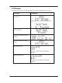
The following table describes the messages displayed on the LCD during normal operations.
Drive State
LCD Message
When tape is loaded (if a writeprotected tape is loaded, a write
protected message will be displayed,
see below).
or,
Ready Mode — indicates that the drive is ready for compression
mode or standard mode operation.
PX — indicates the actual partition (X = 0 or 1) currently being
used.
WRT — indicates that the tape is write-enabled.
WPT — indicates that the tape is write-protected.
Tape loaded, Write Protected.
will be displayed, along with the ready screen, while the beeper
sounds an alarm for fifteen seconds. The alarm will then stop
and the ready screen will remain on the LCD. Any attempt to
write to the tape will cause the alarm to sound and the following
message to appear:
Whenever a tape is in motion.
Motion Message = Loading, Unloading, Positioning, Erasing,
Verifying, Cleaning Tape, and Rewinding.
3 arrows =
, or
. The arrows will scroll to the left or right.
Continued on next page.
16
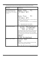
Operation
Drive Operating Condition
Whenever the system is writing to a
tape, this message will alternate with
the ready screen.
LCD Message
.
Writing — indicates the system is writing to the tape.
P — indicates the actual partition currently being used (X = 0 or
1).
XX.X GB — indicates the amount of tape available to be
written to within a partition.
Whenever the system is reading a
tape, this message will alternate with
the ready screen.
.
Reading — indicates the system is reading from the tape.
XX.XGB — indicates the amount of tape used within a
partition.
P — indicates the actual partition currently being used (X = 0 or
1).
Whenever the system is creating a
partition on the tape.
indicates the drive is creating a partition.
— indicates tape motion.
Whenever the system is changing to
another partition on the tape.
occurs whenever an application stores files on more than one
partition.
— indicates tape motion.
Operation
17
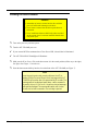
Loading the Data Cassette
Cautions
• Attempting to insert a cassette into the drive with the
power off will result in damage to the drive.
• Never insert a cassette into the drive up side down or
backwards.
• Never install more than one label in the place provided
on the cassette, there is a strong possibility that the tape
will jam on eject.
p
Turn on the power to your host system.
p
Turn the AIT-70D/100D power on.
4 If your external SCSI bus terminator has a Term Power LED, it should also be illuminated.
4 The AIT-70D/100D LCD backlight will illuminate.
p
Make sure the Write-Protect Tab on the data cassette is in the record position (all the way to the right).
See figure 4 in Chapter 1: Introduction.
p
Insert the data cassette halfway into the slot on the front of the AIT-70D/100D (see Figure 7).
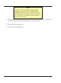
Note
Inserting a write-protected cassette will cause the LCD to
display a “Write Protected Tape In Drive” message and the AIT70D/100D will sound an alarm for approximately 15 seconds. The
message will not be displayed again unless a write command is
issued by the host; if this occurs, the write-protected message
will again be displayed. The message will remain until the host
issues another valid command or the cartridge is ejected.
18
Operation
Figure 7. Inserting a Data Cartridge
p
Gently push the cassette into the drive opening until you feel a resistance. The drive will pull the
cassette the rest of the way in.
p
A load sequence will initiate and the drive will go on-line. The Status may flash, signifying that the
cartridge is being loaded (refer to Appendix C for specific drive LED status codes).
4 When the Status LED is steady, the unit is ready.
Removing the Data Cassette
Premature removal of the data cassette (i.e., while the Status LED is on and data is being written to the tape)
can cause the entire tape directory to be lost.
4 Make sure that the Status LED is not flashing and the tape is not moving.
p
Push the eject button on the front of the AIT-70D/100D.
Operation
19
Note
Many application software packages have the capability of
locking the cartridge into the drive via a MEDIA REMOVAL
PROHIBITED command. If you must remove the cartridge, even
when the application is preventing you from doing so, press the
Eject button 3 times consecutively, or hold the eject button
depressed for 30 seconds.
4 The Status LED may begin flashing while the tape is being returned to the cassette. This can take up to a
minute. Then the cassette will be ejected from the drive and can be removed.
p
Remove the cassette from the drive.
4 The drive Status LED should be out.
20
Operation
Chapter
4
Maintenance
This Chapter . . .
p
describes the LCD messages displayed during the drive firmware upgrade process.
p
explains how to clean the tape head.
p
describes how to clean the enclosure.
21
The AIT-70D/100D is a highly sophisticated unit. No routine maintenance is required apart from cleaning the
heads whenever the Cleaning Request message is displayed by the front panel Status LED (see Media
Warning Message in Chapter 4 of this manual).
The drive firmware is subject to being upgraded by the manufacturer. If the manufacturer upgrades the drive
firmware, specific instructions on how to perform the upgrade will be included with the upgrade tape.
If your AIT-70D/100D fails to operate correctly, immediately call the ATAC (see When You Need Assistance
in Chapter 5 of this manual).
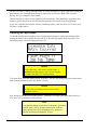
Cleaning the Tape Heads
You should clean the tape heads whenever the Cleaning Request message is displayed on the Status LED.
Cleaning the heads is also a sensible first step if the Error Rate Warning appears on the Tape LED. The
following messages will also be displayed on the LCD:
Caution
Using cloth swabs, cotton swabs, cleaning agents, or
unapproved cleaning cassettes will void your warranty.
Use only a Sony SDX-TCL cleaning cassette.
To clean the heads, insert the cleaning cassette in the drive. The drive will automatically load it and clean the
heads. After the cleaning operation, the cassette is ejected.
Caution
Do not remove the cleaning cassette before the drive
completely ejects it.
Write the date on the label of the cleaning cassette , so that there is a record of how many times it has been
used. After 70 uses, discard the cleaning cassette.
Note
If you load the cleaning cassette into the drive after it has been
used 70 times, it will go through the motions but it will not
clean the head (the cycle is noticeably shorter). Be sure to
discard the cleaning cartridge after 70 uses.
22
Maintenance
Cleaning the Enclosure
The outside of the enclosure can be cleaned with a damp towel. If you use a liquid all-purpose
cleaner, apply it to the towel. Do not spray the enclosure.
Maintenance
23
Blank Page
24
Maintenance
Chapter
5
Troubleshooting and
Diagnostics
This Chapter . . .
p
provides information on drive warning lights and the Media Warning message.
p
describes the effects of high humidity on the AIT-70D/100D.
p
explains what to do when you need technical support.
25
Warning Signals
The drive used in the AIT-70D/100D employs three LEDs on the front panel to indicate SCSI activity,
cassette status, and drive fault conditions through a pattern of codes. The LCD also displays error messages
as described in the following section.
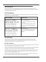
LCD Error Messages
Whenever an error occurs, perform the actions listed in the following table. If the error message reappears,
call the ATAC or you reseller for assistance.
LCD Error Message
Actions to Take
Data Cartridge Problem:
• Clean the Drive Head using new cleaning
cartridge.
aa = error status 0, reported by drive
bb = error status 1, reported by drive
cc = error status 2, reported by drive
• Use new data cartridge and retry operation.
• Power-cycle the AIT-70D/100D and retry
operation.
Hardware Problem:
• Use new data cartridge and retry operation.
aa = error status 0, reported by drive
Power-cycle the AIT-70D/100D and retry
operation.
bb = error status 1, reported by drive
cc = error status 2, reported by drive
Drive LED Status
The drive in the AIT-70D/100D employs its front panel LEDs to indicate SCSI activity, drive fault
conditions, and cassette status. Refer to the following tables and figures for locations of the LEDs and
descriptions of the status and error codes displayed by the drive.
Media Warning Message
If an excessive number of read-after-write errors are detected during normal operation of the AIT-70D/100D,
a Media Warning message will be displayed by the Tape LED.
Usually, the Media Warning message is displayed by the drive because of dirty heads, so the heads should be
cleaned (see Cleaning the Tape Head in Chapter 4 of this manual) and the operation tried again.
If the Media Warning message reappears, repeat the operation with a different (preferably new) tape. If this
clears the Media Warning message, the first tape is nearing the end of its life. Copy all the data on that
cassette to a new cassette and discard the old one.
If it does not clear the Media Warning message, and you are unsure of the problem source, call the ATAC
(for more information see When You Need Assistance later in this chapter).
26
Troubleshooting and Diagnostics
The Media Warning message is also cleared from the drive by loading a new tape, or by cycling power to the
AIT-70D/100D.
Sony SDX-300C/SDX-500C Drive
Busy LED
Tape LED
Status LED
(Top)
(Middle)
(Bottom)
MEANING
Off
Off
Off
No cartridge present/no activity
On
Off
Off
SCSI activity
Fast flashing
Fast flashing
Off
Drive loading/unloading
Fast flashing
Fast flashing
On
Drive loading/unloading, cassette write protected
Off
On
Fast flashing
Cleaning cartridge at end of media (no cleaning cycles
remaining)
Off
On
Off
Cartridge loaded/no activity
On
On
Off
Cartridge loaded/SCSI activity
Fast flashing
On
Off
Cartridge loaded/SCSI and drive activity
*
On
On
Cartridge loaded/write protected
*
Slow flashing *
Media Warning Message — excessive errors detected
Slow flashing *
*
High humidity detected
*
*
Slow flashing
Cleaning request
*
*
Flash code 2
Drive self-test failure detected
Flash code 1
*
*
Waiting for reset
*
Flash code 1
*
Waiting for eject
Table 4. Sony SDX-300C/SDX-500C Front Panel LEDs
Key:
Fast flashing = ON for 0.25 sec., OFF for 0.25 sec.
Slow flashing = ON for 3.5 sec., OFF for 0.5 sec.
Flash code 1 = ON for 0.25 sec., OFF for 1 sec.
Flash code 2 = ON for 0.25 sec., OFF for 0.25 sec., ON for 0.25 sec. OFF for 0. 05 sec.
Troubleshooting and Diagnostics
27
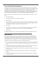
Causes of the Media Warning Message
The Media Warning message appears whenever the drive has determined that low level error performance
has degraded to a point where drive head cleaning is absolutely required. It does this by counting the number
of C3 (soft) errors as well as the RAW (Read After Write) errors over a number of Mbytes. When a
predetermined error rate threshold is reached, the drive displays the warning. When a tape is loaded, it may
take several minutes for the indication to come on because the drive will wait for a specific number of bytes
to be written. A hard (non-recoverable) error will cause the warning to be displayed immediately.
The most common causes of the Media Warning Message, in order of highest rate of occurrence, is listed
below:
•
Dirty ("Stained") heads.
•
A cleaning cycle must be executed to clear this indication.
•
Bad environment.
•
Data errors result from a number of factors, each of which subtract from the margin between good data
recovery and an error. Electrical or magnetic interference can decrease this margin. High levels of dust
contamination, high humidity, and heat can also be significant factors.
•
Worn heads.
•
The tape heads will eventually wear out causing the time between cleanings to get shorter and shorter.
Tape head failure is usually predicted at about 12% of the 200,000-hour MTBF rating.
•
Defective drive.
Drive amplifier settings could be off, causing error rate degradation. The drive could simply have failed.
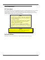
High Humidity
If the drive detects high humidity, a warning is displayed by the drive LEDs. Any commands that are
currently being executed are aborted, and any commands that access the tape are rejected with a CHECK
CONDITION. In addition, the tape is unthreaded to prevent tape and head damage. As soon as the drive
detects that humidity is at an acceptable level, it will once again respond to commands that access the tape.
To minimize the chance of condensation, please observe the following guidelines:
28
p
If you expose cartridges to temperatures outside the operating limits (5-40°C/40-113°F), stabilize them
before you use them. To do this, leave the cartridges in the operating temperature for a minimum of two
hours.
p
Avoid temperature problems by ensuring that the ventilator slots at the front of the drive and the grille
on the side of the chassis are not obstructed so that the drive has adequate ventilation.
p
Position the drive where the temperature is relatively stable, for example, away from open windows, fan
heaters, and doors.
p
Avoid leaving cartridges in severe temperature conditions, for example, in a car standing in bright
sunlight.
p
Avoid transferring data (reading from and writing to cartridges) when the temperature is changing by
more than 10°C per hour.
Troubleshooting and Diagnostics
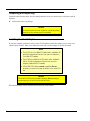
When You Need Assistance
When Calling ATAC
Technical support is provided free of charge to all ADIC customers’ 24 hours a day. Customers must provide
serial numbers to qualify for this support.
Warranty exchange service is available to all customers who have validated their warranty by returning the
warranty card shipped with their unit, in accordance with the terms of the warranty.
The following steps will help you take full advantage of your call to ADIC:
p
Make certain that you have reviewed the documentation to solve any problems. Most questions are
answered in your documentation.
p
Identify whether the software or hardware has worked properly at anytime before this call. Have you
changed anything recently?
p
Pinpoint the exact location of your problem, if possible. Note the steps you took which led to the
problem. Are you able to duplicate the same problem or is it a one-time occurrence?
p
Note any error messages displayed on your PC screen or file server. Write down the exact error
message.
p
If at all possible, call while at your computer with your ADIC system installed and turned on.
p
If running on a network, have all information available (i.e., type, version #, network hardware, etc.).
p
Be prepared to provide the following information:
•
Your name
•
Company name
•
ADIC model number
•
Serial number of ADIC unit
•
Hardware configuration
•
Software configuration
•
A brief description of your problem
•
Where you purchased your ADIC system
Having this information available when you call for customer support will enable ADIC to resolve your
problem in the most efficient manner possible.
p
In the United States and Canada, call ADIC’s Technical Assistance Center at: (800) 827-3822
p
In Europe, call ADIC’s Technical Assistance Center at: 00.800.9999.3822
Note
ADIC 's telephone support services are not provided as a
substitute for proper review and use of applicable ADIC user
manuals.
Troubleshooting and Diagnostics
29
RMA (Return Material Authorization)
When it has been determined that there is a hardware problem with an ADIC system, the ATAC will provide
you with an RMA number. The warranty card must be completed and returned to ADIC before the warranty
is valid. (Customers who have not completed warranty registration can fax the warranty card to ADIC. Call
the ADIC Sales Department at (206) 881-8004 for details.)
Warranty exchange service is provided at no charge to customers with validated warranties. If the item is
NOT in warranty, the repairs will be billable. Therefore, we will need a PO number at the time the RMA
number is issued. However, with first-time customers, it may be necessary to ship the system back C.O.D. for
the first repair until credit information can be obtained by the accounting department.
30
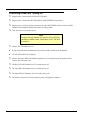
p
Be sure all procedures in the ADIC user's manual have been checked and tried.
p
When calling for an RMA number have the exact ADIC model number, serial number, and a
brief, descriptive explanation of the problem found. Be sure you give complete address
information (e.g., any mail stops or special codes) at the time the RMA is issued.
p
Please send the complete ADIC system, i.e., interface cables, and the unit, if possible. A
defective component such as a cable, or the unit, may be the cause of problems.
p
The RMA number should be kept as a reference for calling to check on the status of an open
RMA. It must also be written on the outside of the package for identification purposes.
Troubleshooting and Diagnostics
Appendix
A
Specifications
This Appendix . . .
p
contains specification information on the AIT-70D/100D.
31
Specifications
Drive
Approved Types:
Sony model SDX-300C
Sony model SDX-500C
Enclosure
Media Type:
A-ME
Indicators/Controls:
Busy, Tape, and Status LEDs
Electrical Interface:
Fast Wide SCSI
Wide Ultra SCSI
Physical Interface:
68-contact shielded high-density device connector
Reliability
Maintenance:
Use cleaning cassette whenever the Status LED displays the
Cleaning Request message
MTBF:
More than 200,000 power-on hours
MTTR:
Within 30 minutes
Physical
Dimensions:
3.9375"(h) x 4.5625" (w) x 8.75 (d)
Weight:
5.5 lbs.
Power Consumption:
less than 40 watts
Environment
32
Electrical:
100-240 Vac, 50-60 Hz, 0.6 - 0.3A
Temperature:
5 °C to 40° C (Operating)
-40° C to 70° C (Storage/Shipping)
Humidity:
20% to 80% (Operating)
5%to 95% (Storage/Shipping)
Vibration:
0.25G (5-500 Hz) (Operating)
0.5G (5-500 Hz) (Storage/Shipping)
Shock:
2G Operating
30G Storage/Shipping
Specifications
Appendix
B
Glossary
This Appendix . . .
p
contains terms and definitions of expressions commonly used with the AIT70D/100D and AIT drives.
33
34
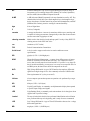
AIT
Advanced Intelligence Tape is a new tape technology developed by Sony. It
incorporates a new recording format, MIC (Memory In Cassette) capabilities,
and uses AME (Advanced Metal Evaporated) media.
A-ME
A-ME (Advanced Metal Evaporated) is the tape formulation used by AIT. Key
characteristics include 100% pure cobalt magnetic layer, dual magnetic layer
design, the absence of binder material to prevent head contamination, and DLC
(Diamond Like Carbon) protective coating for extreme durability.
byte
8 bits of digital data
C
Celsius (Centigrade)
cassette
A storage medium item. A cassette is sometimes called a tape or cartridge and
is capable of storing vast amounts of magnetically written data. Some cassettes
can store more than 50 gigabytes of data.
cleaning cassette
Media used to clean the drive heads and tape path. Use only a Sony SDX-TCL
cleaning cassette in the SDX-300C drive.
cm
centimeter (0.3937 inches)
FCC
Federal Communications Commission
ferrite bead
A device used to suppress radio noise in certain conditions to meet
specifications.
GB
gigabyte (1 GB = 1,024 Megabytes)
HSM
Hierarchical Storage Management – a system where different types of storage
media are used based on cost and time efficiency. For example, for fastest
access, data is usually stored on a local hard drive. If you have a very large file
that is needed occasionally, you may store it on a tape or on an optical drive. In
an HSM system, the data source should be transparent to the user.
HVD
High Voltage Differential. A type of SCSI interface that employs differential
signal lines at high-voltage levels. Also commonly referred to as Differential.
Hz
Hertz (replacement for "cycles-per-second").
initiator
A host computer system that requests an operation to be performed by a target
device.
KB
kilobyte (1 KB = 1,024 bytes)
LCD
Liquid Crystal Display. A commonly used alphanumeric display that responds
to specific input voltages and signals.
LED
Light Emitting Diode, a commonly used semiconductor device that glows when
supplied with a specified voltage.
Loaded
The tape is loaded after the drive has performed identification and verification
tests, positioned the tape at its beginning, and is ready for access commands.
LVD
Low Voltage Differential. A type of Ultra SCSI interface that uses low- voltage
differential signal lines.
MB
megabyte (1 MB = 1,024 Kilobytes)
Glossary
MIC
Memory In Cassette is a design innovation developed by Sony. Incorporating a
Flash memory IC inside the AIT media cassette allows the architecture to
capture various system and user-related statistics directly within the MIC
structure to enhance data reliability, error prediction and success performance.
mm
millimeter (0.03937 inches)
Off-line
When the drive is off-line, all commands that access the tape will report check
condition status. Generally operations that would cause tape motion, that is;
write, read, and space commands cannot be performed.
On-line
The drive is on-line when a tape is loaded in the drive and the load sequence
has finished. All commands can be executed, including those that set
configurations or run diagnostic tests.
RMA
Return Merchandise Authorization.
RMA number
An identifying number given to a customer who needs to return equipment for
repair, whether under warranty or not.
SCSI
Small Computer System Interface. An industry standard for connecting
peripheral devices and their controllers to a microprocessor. The SCSI
specification defines both hardware and software standards for communication
between a host computer and a peripheral.
SCSI bus
Signal path or line shared by the devices on the same SCSI channel.
Information is sent to all devices throughout the same bus; only the device to
which it is addressed will accept or respond to it.
SCSI ID
The octal representation of the unique address (0 to 15 for SCSI-2 Fast/Wide
buses) assigned to a SCSI device.
SDX
The series name of the media and hardware associated with the AIT format
incorporated in a 3.5 inch form factor.
AIT-70D/100D
An ADIC digital tape system that uses helical-scan technology to back up
networks or stand-alone units.
SDX-300C drive
A Sony AIT-1 drive used in the 100D. It is an enhanced Wide SCSI digital
helical-scan cassette tape subsystem.
SDX-500C drive
A Sony AIT-2 drive used in the 70D. It is an enhanced Wide Ultra SCSI digital
helical-scan cassette tape subsystem.
terminator
A resistor network that absorbs the signal energy at the ends of the SCSI bus in
order to prevent reflections of the signal. Reflections can lead to data errors
thereby causing SCSI devices to retransmit information. This can slow down
the bus speed. A terminator is required at both ends of a SCSI bus. A bus may
be terminated internally (on a device inside the host system) or externally on a
peripheral device.
Off-line
When the drive is off-line, all commands, which access the tape, will report
check condition status. Generally operations that cause tape motion, that is;
write, read, and space commands cannot be performed.
Glossary
35
36
On-line
The drive is on-line when a tape is loaded in the drive and the load sequence
has completed. All commands can be executed, including those that set
configurations or run diagnostic tests.
Semi-loaded
A cartridge is semi-loaded when the cartridge is in the drive mechanism but the
tape is not threaded around the head.
Threaded
The tape is threaded when it is physically taken onto the reels and positioned
on the head.
Unloaded
A cartridge is unloaded when it is physically ejected from the drive.
Glossary
Index
37
—A—
AC Power Connector, 4
Active Head Cleaner, 2
active termination, 14
ADIC Technical Assistance Center, 7, 24, 29, 33
Advanced Intelligence Tape, 38
AIT, iii, 2, 3, 6, 36, 38, 39
AIT data cassette, 5
ALDC, iii, 2
AME, 2, 38
application software, 2, 22
Application Software, 7
ASPI, 3
—B—
backup software, 14
Bad environment, 31
Busy LED, 4, 16, 30, 36
drive status, 2, 4
dust contamination, 31
—E—
eject button, 4, 21, 22
electrical interference, 31
EMI/RFI Compliance, v
Erasing, 18
error codes, 28
error messages, 2, 4, 28, 32
Error Rate Warning, 24
extreme environmental conditions, 2
—F—
ferrite bead, 38
file access time, 2
Flash memory IC, 5
front panel LCD display, 38
—C—
cassette status, 28
Causes of the Media Warning Message, 31
Check the Terminating Resistor, 13
cleaning cassette, 24, 25, 38
Cleaning Request message, 2, 24, 36
Cleaning Tape, 18
Cleaning the Enclosure, 25
Cleaning the Tape Heads, 24
compressed mode, 5
Connecting More than One 70D/100D, 12
Copyright Notice, iii
Copyright Notice (Europe), iv
—D—
Declaration of Conformity, vi
Defective drive, 31
Dirty ("Stained") heads, 31
DLC, iii, 2, 38
drive fault conditions, 28
drive firmware, 24
drive head cleaning, 31
Drive LED Status, 28
drive LEDs, 28, 31
Drive Operating Condition, 19
Drive State, 17, 18
38
Index
—H—
heat, vii, 31
helical scan device, 5
hierarchical storage management, 38
High Humidity, 31
host adapter, 10, 11, 13
host computer, 4, 7, 10, 11, 16, 38, 39
host system, 7, 16, 20
hosting environment, 3
HSM, 38
—I—
Installing the Backup Software, 14
Installing the Host Adapter, 10
interface cable, 4, 11
—J—
jack screws, 11
—L—
label, 20, 25
LCD, 2, 4, 16, 17, 18, 20
LCD Error Message, 28
LCD Message, 17, 18, 19
LED status codes, 21
load sequence, 21, 39, 40
Loading, 18
loading a tape, 17
Loading the Data Cassette, 20
—M—
magnetic interference, 31
media, 38
MEDIA REMOVAL PROHIBITED command, 22
Media Warning Message, 29, 31
MIC, iii, 2, 5, 38, 39
Motion Messages, 18
—N—
native mode, 5
near-line data, 2
—O—
off-line data, 2
on-line, 21
operational messages, 2, 4
—P—
packing materials, 10
passive termination, 14
Positioning, 18
power cord protection, vii
power sources, vii
Power Switch, 4
Precautions, viii
—R—
read after write errors, 29, 31
Ready Mode, 18
ready screen, 18, 19
Removing the Data Cassette, 21
Return Material Authorization, 33, 39
Rewinding, 18
RMA, 33, 34, 39
RMA number, 33, 34, 39
routine maintenance, 24
—S—
Safety Warnings, vii
SCSI, 39
SCSI activity, 28
SCSI address, 12, 39
SCSI bus, 14, 39
SCSI bus connector, 11
SCSI bus terminator, 16, 20
SCSI buses, 13
SCSI cable, 11
SCSI channel, 3, 4, 12, 39
SCSI channel connectors, 4
SCSI connector, 12
SCSI controller, 7
SCSI device connector, 11
SCSI devices, 3, 12, 13
SCSI Host Adapter, 2, 7, 13
SCSI ID, 4, 12, 13
SCSI ID switch, 4, 13
SCSI interface, 2
SCSI interface cable, 11
self-test, 17
servicing, viii
Setting the SCSI ID, 12
severe temperature conditions, 32
shielded interface cable, 11, 12
single-ended SCSI bus, 14
specifications, 38
Status, 21
status codes, 28
Status LED, 2, 4, 16, 21, 22, 24, 30, 36
sustained data transfer rate, 2
switches and indicators, 3
—T—
tape directory, 21
tape head contamination, 2
Tape head failure, 31
Tape LED, 4, 16, 24, 29, 30, 36
Tape loaded, Write Protected, 18
tape motion, 19, 39, 40
tape partition, 18, 19
temperature operating limits, 32
temperature problems, 32
Term Power LED, 16, 20
termination, 13
terminator, 40
Index
39
—U—
Unloading, 18
unloading a tape, 17
—V—
ventilation, vii
Verifying, 18
40
Index
—W—
Warning Signals, 28
Warranty exchange service, 32, 33
Worn heads, 31
write protected message, 18
Write Protected Tape In Drive message, 20
Write-protect tab, 6, 20
write-protected message, 20
write-protected tape, 18