1
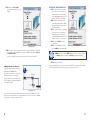
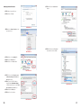
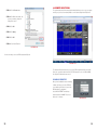
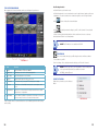
Remote Monitoring
Setup Guide
QS SERIES DVR MODELS
PC with Windows
Operating System
iPhone
Android
BlackBerry*
* Select Models
Setup Guide for Remote Internet and Smartphone Monitoring,
MyQ-See DDNS, and Email Notification
1
About this Manual
Thank You for Choosing a Q-See Product!
All of our products are backed by a conditional service warranty covering all hardware for 12
months from the date of purchase. Additionally, our products also come with a free exchange
policy that covers all manufacturing defects for one month from the date of purchase.
Permanent upgrading service is provided for the software and is available at www.Q-See.com.
Be certain to make the most of your warranty by completing the registration form online. In
addition to warranty and technical support benefits, you’ll receive notifications of product
updates along with free downloadable firmware updates for your DVR. Register today at
www.Q-See.com!
This remote monitoring guide contains information extracted from the user’s guide and
presents it in this smaller document for your convenience. and was accurate at the time it
was completed. However, because of our ongoing effort to constantly improve our products,
additional features and functions may have been added since that time and on-screen
displays may change. We encourage you to visit our website at www.Q-see.com to check for
the latest firmware updates and product announcements.
Throughout the manual we have highlighted warnings and other important information that will
assist you in operating your new system in a safe and trouble-free manner. Please take the
time to read and follow all instructions and pay attention to alerts as shown below:
IMPORTANT! Red boxes with this icon indicate warnings. To prevent
possible injury or damage to the product, read all warnings before use.
Please see the back of this manual for exclusions.
NOTE! Text in blue boxes with the Information icon offer additional guidance
and explanations about how to make the most out of your system.
© 2011 Q-See. Reproduction in whole or in part without written permission is prohibited. All
rights reserved. This manual and software and hardware described herein, in whole or in part,
may not be reproduced, translated, or reduced to any machine-readable form without prior
written approval.
Trademarks: All brand names and products are trademarks or registered trademarks of their
respective owners.
Q-See is a registered trademark of DPS, Inc.
Disclaimer: The information in this document is subject to change without notice. The
manufacturer makes no representations or warranties, either express or implied, of any kind
with respect to completeness of its contents.
Manufacturer shall not be liable for any damages whatsoever from misuse of this product.
2
3
4. MOBILE SURVEILLANCE
TABLE OF CONTENTS
1. REMOTE ACCESS
1.1 Connecting your DVR to a Network
Before you get started
Obtaining an IP address
Static IP
6
6
6
7
9
1.2 Opening Ports
UPnP
DMZ
Confirming that ports are opened
10
10
11
12
1.3 Connecting via a modem
PPPOE
12
12
1.4 Activating DNS (Domain Name Server)
13
1.5 Setting up Dynamic Domain Name Service (DDNS)
14
1.6 Resolving Connection Issues
Determine the number of routers on the network
Setting up DMZ in router 2
15
15
17
2. REMOTE MONITORING
33
4.2 Mobile surveillance software
Android
BlackBerry
iPhone and iPad
Symbian Operating System
Windows Mobile
34
34
37
39
41
44
Q-SEE PRODUCT WARRANTY
Questions or Comments? Contact Us
47
48
18
2.1 Accessing your DVR remotely
Accessing the DVR using Internet Explorer
18
18
2.2 Remote monitoring Logging in remotely
The live view window
Recording
PTZ control
Screen captures Playback
Search
Remote backup
Remote setup
23
23
24
25
26
26
27
28
29
30
3. E-MAIL NOTIFICATION
33
4.1 Enabling mobile surveillance
32
Rev. 1.6 10/31/11
4
5
REMOTE ACCESS
CHAPTER 1
In order to access your DVR remotely, you must connect it to a router or a modem. Using
a router allows you to connect to your DVR from other computers on your LAN (Local Area
Network) in addition to over the Web. Directly connecting to a modem makes your DVR
available for connection through the Internet only.
If you are using a router and wish to access your DVR from outside your LAN either over the
Internet, or from your mobile device, then that router must be connected to the Internet. The
instructions below will guide you through the process of configuring your DVR for remote
access. Once completed, you will be able to access and control your system using one of
two addresses. You will have a local IP address usable by computers connected to the same
router as your DVR. This address can also be used by wireless devices as long as they are
able to also connect to your router’s WiFi signal. Once you leave the area covered by your
local network, you will need to use a second address to access the DVR. This is the address
which will allow you to connect to your system from anywhere in the world with Internet
access. And, by using Q-See’s free DDNS service, MyQ-See.com (more on this later), you’ll be
able to do so using a conventional web address.
OBTAINING AN IP ADDRESS
Each device on a network - both a LAN or the Internet - has a specific IP address. This
address is what allows different devices on the network to communicate with each other. Your
QS-series DVR displays its IP address in the Network Setup window.
STEP 1. Using the mouse, right-click
on the screen and then select Main
Menu in the pop-up shortcut menu.
STEP 2. Select ADVANCE in the Main
Menu window.
If you are using a router, proceed with Section 1.1. If you are connecting directly to the
Internet via a modem then begin with Section 1.3.
MAIN MENU
KEY LOCK
CHN SWITCH
DIGITAL ZOOM
VIDEO SEARCH
PICTURE 1-1
PTZ
MUTE
MANUAL REC
STOP REC
ROTATION
ADVANCE
1.1 CONNECTING YOUR DVR TO A NETWORK
First and foremost, you will need to physically connect your DVR to a router. This router can
be part of an existing network of computers, or it can be the router/modem supplied by your
Internet Service Provider (ISP) to connect you to the Internet. This connection will be made by
plugging the included Ethernet cable into the port on the back of the DVR marked RJ45. Your
DVR is not designed to be connected wirelessly to a network. It is also recommended that the
router that the DVR is connected to should be connected directly to the Internet rather than
to another router if Internet access is desired as multiple routers can create problems with
connectivity. You will also need to have a computer connected to the same router - at least
temporarily - to make certain settings. If, after following the instructions you are still not able
to access your DVR, please see Section 1.6 Resolving Connection Issues later in this
chapter.
SEARCH
RECORD
HDD
BASIC
ADVANCE EXIT
PICTURE 1-2
STEP 3. Click on NETWORK in the
Advanced Settings Menu.
BEFORE YOU GET STARTED
You will need to have:
• Your router’s brand, model number and manual. The manual is also usually available on
your router’s manufacturer’s website.
PICTURE 1-3
• The “Manuals and Software” CD that came with your DVR. It contains necessary software
and links to other important programs which are mentioned in this guide.
• Your router’s password (the default password should be in your router’s manual).
6
7
STEP 4. Make sure that DHCP is
selected in the drop down menu at
the top (item “a”). If it is not, select
it, click Apply and then Exit before
restarting the DVR and returning to
this window.
Write down the DVR’s IP address
(Item “b”). At this time, you should
consult your Router’s manual to
determine it’s IP address, also known
as the Internet- or Network Gateway
address.
STATIC IP
a
NETWORK SETUP
TYPE
DHCP
MEDIA PORT 09000
WEB
PORT 00080
IP
ADDR 196.281.941.066
AUTO
075.004.019.001
DNS
199.210.011.701
DDNS SETTINGS
UPNP
DEFAULT
The first number you wrote down, the DVR’s IP address, is what you can use to access your
DVR while you are on the same network. This address can be entered into a Windows
Explorer browser as you would a regular web address. See Chapter 2 Remote Monitoring
for full instructions on using this feature.
b
OPEN
However, in the event of a power outage or other event that causes the router to restart, the
router will often reassign a new IP address to connected devices and you will have to repeat
the procedure above to be able to log into your DVR.
CLOSE
APPLY
EXIT
PICTURE 1-4
In some situations where only your router is disconnected or powered off whlle your DVR is
unaffected, you may have to restart your DVR to refresh the information on the Network Setup
page to get the new IP address.
To avoid this issue, return to the Network Setup window and change the pull-down Type
menu to Static. Click on Apply to save your changes before exiting the menu.
For your convenience, the table below lists some common router manufacturers along with
their most frequently used default gateway adresses.
Router Manufacturer
Default IP Addresses
3Com
192.168.1.1
Apple
10.0.1.1
Asus
192.168.1.1, 192.168.1.220
Belkin
192.168.2.1, 10.1.1.1
Buffalo
192.168.11.1
Dell
192.168.1.1
D-Link
192.168.0.1, 0.30, 0.50, 1.1, 10.1.1.1
Linksys
192.168.0.1, 1.1
Microsoft
192.168.2.1
Motorola
192.168.10.1, 20.1, 30.1, 62.1, 100.1, 102.1, 1.254
MSI
192.168.1.254
Netgear
192.168.0.1, 0.227
Senao
192.168.0.1
SpeedTouch
10.0.0.138, 192.168.1.254
Trendnet
192.168.0.1, 1.1, 2.1, 10.1,
U.S. Robotics
192.168.1.1, 2.1, 123.254
Zyxel
192.168.1.1, 2.1, 4.1, 10.1, 1.254, 10.0.0.2, 0.138
8
IMPORTANT! As of this writing, 2Wire brand routers do not support Static
IP. Because of this, in the event that your router has to restart, you will need
to repeat the steps to obtain the new IP address. Connecting the router to an
uninterruptible power supply (UPS) can prevent this issue.
9
1.2 OPENING PORTS
DMZ
If you wish to access your DVR outside of your local network, you will need to configure your
router to allow data to pass through its firewall using specified ports. This is referred to as
Port Forwarding and does not constitute a security risk for your network as it only allows for
specific communication to and from your DVR. For QS-series DVRs, the three ports that will
be forwarded are; 80, 100 and 9000.
DMZ stands for Demilitiarized Zone and is a way to instruct your router to allow data to pass
to and from the ports you specify. Most current models of routers feature DMZ.
Below are two methods available which will forward ports for the vast majority of users;
UPnP and DMZ. Please be advised that you will only need to use one process or the other to
connect and implementing both will actually cause connection difficulties.
UPNP
UPnP or Universal Plug ‘n’ Play is an industry-standard set of networking protocols which
allows networked devices to instantly locate each other and communicate. Most routers
produced since 2009 feature UPnP. At this time you should consult your router’s manual
to ensure that it features UPnP. As of this writing, 2Wire brand routers DO NOT have UPnP
capability and users of these routers as well as other routers without UPnP functionality will
need to use the DMZ method described immediately below this section to forward their ports.
By default, your DVR comes pre-configured
with UPnP turned on. This setting is
accessible in the Network Setup window. If
UPnP is not selected as Open, you will need
to select that option and then click Apply.
Proceed to the end of this section for
instructions on how to confirm that your ports
are open using an online tool.
DHCP
MEDIA PORT 09000
WEB
PORT 00080
IP
ADDR 196.281.941.066
AUTO
075.004.019.001
DNS
199.210.011.701
DDNS SETTINGS
UPNP
DEFAULT
OPEN
CLOSE
APPLY
EXIT
PICTURE 1-5
IMPORTANT! If you connect your system to your network using UPnP
you should NOT forward your ports as described in DMZ, as it will create
connectivity problems. You may skip to Confirming that Ports are
Opened.
10
The exact location of DMZ within the router’s settings vary by manufacturer so please consult
your router’s manual for the location of this feature. The method for accessing your router’s
settings, however, is pretty standard.
STEP 1. Open a web browser and enter
your router’s IP address into the
address bar. This address is listed in
your Router’s manual. This should
open your router’s control panel.
Pictures 1-6 and 1-7 show two examples
of the location of the DMZ controls.
STEP 2. Once you have located the
DMZ controls, ensure that they are
enabled or turned on.
NETWORK SETUP
TYPE
Accessing your router’s DMZ controls:
PICTURE 1-6
STEP 3. Enter the DVR’s IP address in
the area provided. This is the first
string of numbers you wrote down
in Section 1.1 Obtain an IP
Address.
STEP 4. Click on Apply or Save as
appropriate to preserve your settings.
PICTURE 1-7
11
CONFIRMING THAT PORTS ARE OPENED
1.4 ACTIVATING DNS (DOMAIN NAME SERVER)
Whether you used UPnP or DMZ to open your ports, you should confirm that they have
been opened without being blocked by going to www.canyouseeme.org using a computer
connected to the same router as the DVR.
Once you have completed the previous sections, you are able to operate your DVR remotely.
However, in order to activate features such as the ability to send e-mail alerts from your
system as well as being able to access it using a conventional web address, you will need to
obtain the DNS (Domain Name Server) number. You will be obtaining this number from your
router and entering it into the appropriate field within your DVR’s Network Setup window.
STEP 1. Enter “80” into the box labeled
“What Port?”
Browser - Windows Internet Explorer
http://canyouseeme.org/
STEP 2. Click on the Check button
STEP 3. You should see a green
“Success” message.
If you get a red error message, you will need
to return to the DVR’s Network Settings
page and change the Web Port to 81, 83
or 85 and click Apply to save your changes.
The DVR will need to reboot to use the new
settings. You can then reattempt the check
by entering that new number in the Port field.
Open Port Check Tool
CanYouSeeMe.org - Open Port Check Tool
This page will serve as a free utility for remotely verifying a port is open or closed. It will
be useful for users who wish to check to see if a server or ISP is blocking certain ports.
Your IP: 81.919.622.24
What Port?
Check
Success: I can see your service on
81.919.622.24 on port (80)
Your ISP is not blocking port 80
PICTURE 1-8
STEP 4. Repeat for ports 100 and 9000. If ports 100 and 9000 are blocked, then use a
number in that range (ie; 110, 9100, etc.)
This website will also display your Public IP address near the top of the page above the box
where you entered your port number. This is the number which you will use to access the DVR
Fine
using a web browser or your mobile device from outside
of your local network (away from
the building in which your DVR is located). Please note that if you had to use a different port
number than 80 for the web port, you will have to add a colon (:) and that port number to the
end of the address shown. Example 82.919.622.24:81.
1.3 CONNECTING VIA A MODEM
STEP 1. Open
a web browser and enter
Page Safety Tools
your router’s IP gateway address into
the address bar. This address is the
second set of numbers you wrote
down in Section 1.1 Obtain an IP
Address and it ends with 001. This
should open your router’s control
panel.
Contact your ISP for the User Name and
Password needed for the router. Select
PPOE from the Type pull-down menu and hit
OK. Enter the User Name and Password into
the appropriate fields.
http://81.919.622.24
Router
SETTINGS
DEVICE INFO
STATUS
ADVANCED
DEVICE INFORMATION
LOGS
All of your Internet and network connection details are displayed on t
STATISTICS
INTERNET SESSIONS
WAN
MAC Address :
IP Address :
Subnet Mask :
Default Gateway :
Primary DNS Server :
Secondary DNS Server :
Advanced DNS :
ROUTING
WIRELESS
STEP 2. Locate your router’s Status
window (it may also be named
“Information” or “Info”), it will list the
DNS number – copy this down.
00:24:01:77:f9:00
81.919.622.249
255.255.255.0
81.919.622.24
10.6.196.6
(null)
Disabled
PICTURE 1-10
Each brand of router is different. Picture 1-10 shows an example of the location of the DNS
number in a router’s status window.
STEP 3. Return to the Network Setup
window in your DVR and enter the
DNS number into the field marked
Protected Mode: On
100%
DNS using the Virtual Keyboard.
In cases where the DNS number on
your router only shows one or two
digits in a section you should enter
zeroes BEFORE the number(s) to
complete the three-digit section.
PPPOE
If you are going to attach the DVR directly to a DSL or Cable modem instead of a router you
will want to select the PPPOE option in the NETWORK options. This method is instead of
UPnP or DMZ and only applies if you are not using a router.
Browser - Windows Internet Explorer
NETWORK SETUP
TYPE
DHCP
MEDIA PORT 09000
WEB
PORT 00080
IP
ADDR 196.281.941.066
AUTO
075.004.019.001
Fine
DNS
010.006.196.006
DDNS SETTINGS
UPNP
DEFAULT
OPEN
CLOSE
APPLY
EXIT
PICTURE 1-11
STEP 4. Click Apply to save your
changes before exiting the window.
You will need to restart your DVR for
the changes to take effect. If you are
continuing on with the next section,
Setting up DDNS, you can wait
until making those settings before
restarting.
PICTURE 1-9
12
13
1.5 SETTING UP DYNAMIC DOMAIN NAME SERVICE
1.6 RESOLVING CONNECTION ISSUES
This is an optional step which allows you to take advantage of Dynamic Domain Name
Service, or DDNS. Not to be confused with DNS in the previous section, DDNS allows you to
enter a conventional web address when remotely logging into your DVR from outside of your
network. It also allows you to avoid having to repeat steps in Obtain an IP Address when/
if your ISP reassigns IP addresses. Q-See offers DDNS service for free at www.MyQ-See.com
and your DVR is configured accept account information from that site.
There are several hardware-related situations which can prevent the DVR’s port from being
properly forwarded. The presence of multiple routers or the routers not featuring UPnP or
DMZ are the two most common issues.
STEP 1. Open a browser window and go
to www.MyQ-See.com
NEW USER REGISTRATION
EMAIL ADDRESS
DETERMINE THE NUMBER OF ROUTERS ON THE NETWORK
If there is more than one router between the DVR and the Internet it will block communication
to and from your system. To find out the number of routers on your network, you will need to
download a FREE router detection program.
PASSWORD
STEP 2. Register with the website and
follow the instructions for creating
a domain name. The website will
display your pubic IP address and
your domain name which will look like
this: http://example.MyQ-See.com
PASSWORD
CONFIRM
FIRST NAME
STEP 1. Go to http://www.pcwintech.
com/shanes-toolbox
LAST NAME
SECURITY
QUESTION..
My first phone number
STEP 2. Click on Detect Multiple
Routers to begin the download.
ANSWER
CONFRIM
YOU’RE HUMAN
New Captcha
Enter the text you see above
Submit
Reset
PICTURE 1-12
STEP 3. Return to the Network Setup
Window in your DVR and click on the
DDNS Settings button to open the
DDNS Setup window.
NETWORK SETUP
TYPE
STEP 3. Unzip the application to install it.
DHCP
MEDIA PORT 09000
WEB
PORT 00080
IP
ADDR 196.281.941.066
AUTO
075.004.019.001
DNS
010.006.196.006
DDNS SETTINGS
UPNP
OPEN
DEFAULT
CLOSE
APPLY
EXIT
PICTURE 1-13
STEP 4. In the DDNS Setup window,
turn DDNS on to reveal the other
required fields. Select MyQ-See.com
as the service and enter the domain
name along with the user name and
password you used to create your
account.
STEP 5. Click on Apply and then exit the
window to return to Network Setup.
Click Apply again and then exit. You
will need to restart your machine for
the settings to take effect.
14
PICTURE 1-13
STEP 4. Click on the detect_routers
application to run it.
DDNS SETUP
DDNS
ON
SERVICE
MYQ-SEE.COM
PICTURE 1-14
HOST NAME
USER NAME
PASSWORD
DEFAULT
APPLY
EXIT
PICTURE 1-14
15
STEP 5. Click on CHECK NOW to
detect how many Routers are in the
network.
SETTING UP DMZ IN ROUTER 2
STEP 1. Login into Router 1 by putting
the IP of Router 1 into the Internet
Explorer browser, as in the example
shown in Picture 1-17 where the IP
address of Router 1 is 192.168.0.1
STEP 2. Find the status page on the
router settings that shows the WAN/
Internet IP address and write it down
this WAN IP address.
STEP 3. Log into the Router 2 by putting
the IP of Router 2 into the Internet
Explorer browser, as in example
shown in Picture 1-17 where the IP
address of Router 2 is 192.168.1.1
STEP 4. Find the DMZ page in the
router settings.
PICTURE 1-15
STEP 6. If there is only one router detected, and you are using UPnP, then you will need
to turn off that setting and attempt to connect using DMZ as described in Section
1.2 Opening Ports.
If you are using DMZ, check to make sure that the UPnP option is turned off.
STEP 5. Enter the WAN IP for Router 1
into the DMZ page and enable DMZ.
PICTURE 1-17
NOTE! If you do not have a DMZ setting in the router, check to see if there
is a Bridge setting. If so, then use the Bridge setting instead of DMZ.
STEP 6. Save your changes.
You have forwarded the ports on the router to which the DVR is connected, to the IP address
of the DVR, and set the primary router to pass the connection to this router.
If Multiple Routers are Detected
If there are multiple routers, you will see a
display similar to Picture 1-16.
If so, it may be preferable to connect your
DVR and computer to the router that
connects directly to the Internet. However,
this is not always possible depending upon
your particular situation.
PICTURE 1-16
In this case, you will need to proceed with the next section and set up DMZ in the second
router to allow communications to pass through it from the first. If only one router is detected
you will need to consult your router’s manual.
16
17
REMOTE MONITORING
CHAPTER 2
STEP 4. Select the desired user account.
2.1 ACCESSING YOUR DVR REMOTELY
Once you have configured the network settings on the DVR to match those on your router and
forwarded the ports needed by the DVR to enable remote access over the Internet, you will be
ready to remotely view your cameras using a webcam program based on an ActiveX control.
For this to work, you will have to enable the ActiveX control options that are built into Internet
Explorer. It is strongly suggested that you be running the latest version of Internet Explorer
(currently IE9). As of this writing, the QS434 is being updated to work with IE9. In the interim,
continue to use IE 8. The instructions below will describe the process using both version 8
and 9 of Internet Explorer.
STEP 5. Select Turn User Account
Control on or off
PICTURE 2-4
ACCESSING THE DVR USING INTERNET EXPLORER
User Account Control for Windows Vista and Windows 7
Some users of computers using Windows Vista or Windows 7 operating systems may receive
an error message informing of a codec that is missing or not installed. This conflict can be
resolved by turning off User Account Control (UAC).
STEP 6. Uncheck the box next to “Use
User Account Control (UAC) to help
protect your computer.”
PICTURE 2-5
STEP 7. You will then be asked to restart
your computer for the change to take
effect.
Windows Vista
STEP 1. Open the Control Panel
(accessible by clicking on the
Windows icon in the lower left of your
screen.
PICTURE 2-1
STEP 2. Select User Accounts and
Family Safety.
PICTURE 2-6
Windows 7
PICTURE 2-2
STEP 1. Open up the Start Menu
(accessible by clicking on the
Windows icon in the lower left of your
screen.
Microsoft Office Outlook 2007
Devices and Printers
Sticky Notes
Default Programs
iTunes
Help and Support
Adobe Acrobat
STEP 3. Select “Add or Remove User
Account.”
All Programs
PICTURE 2-3
STEP 2. Type “uac” into the search bar
and hit ENTER. The User Account
Control will open or you will be offered
a link to click to open it.
uac
Shut down
PICTURE 2-7
STEP 3. Move slider to lowest setting
and press OK.
18
19
STEP 11. Click the Custom level…
button.
Setting Up ActiveX Control
STEP 1. Open Internet Explorer
STEP 2. Click on Tools
PICTURE 2-8
STEP 3. Select Internet Options in the
pull-down menu
PICTURE 2-12
PICTURE 2-9
STEP 12. Pull down the “Reset to:”
menu button and select Low
STEP 4. Click on the Security Tab
STEP 5. Select Trusted Sites
STEP 6. Click on the Sites button
PICTURE 2-10
STEP 7. Uncheck the “Require server
verification (https:) for all sites in
this zone” button.
STEP 8. Type the DVR’s IP address
(obtained during Network Setup)
or DDNS domain name into the “Add
this website to the zone:” box.
PICTURE 2-13
STEP 9. Click the Add button
STEP 10. Close the window.
PICTURE 2-11
20
21
2.2 REMOTE MONITORING
The system features a built-in browser-based software that allows you to access your system
remotely over your local area network (LAN) or over the Internet using Internet Explorer®.
STEP 13. Click the Reset button
STEP 14. Click “Yes” when asked, “Are
you sure you want to change the
setting for this zone?”
STEP 15. Click OK
STEP 16. Click Apply
STEP 17. Click OK
STEP 18. Close Internet Explorer
PICTURE 2-14
You are now ready to access the DVR using Internet Explorer.
PICTURE 2-15
The software will install the first time you access the DVR through Internet Explorer and will
allow you to operate the network remotely. The DVR supports access over LAN and WAN,
also supports IP and domain name access.
LOGGING IN REMOTELY
After you have installed the remote monitoring
software, any time you acces the DVR from
your computer you will have to sign onto the
DVR through the Login window.
Select LAN or INTERNET from the dropdown menu and click LOGIN. The process
will last for 1~2 minutes.
22
PICTURE 2-16
23
Live Viewing Controls
THE LIVE VIEW WINDOW
After logging in, the Remote Surveillance main screen will appear in your browser.
• Click LIVE at the top of the main screen.
• Click the display mode icons to view the main screen in single-channel, quad, or split-screen
configurations. You can also double-click a channel at any time to view it in single-channel.
• Click
to show or hide all the channel windows.
• Click
to start/stop manual recording to your PC on ALL channels. For more details
see RECORDING.
• Select a channel (outlined in red) and then click the audio bars to increase or decrease
listening volume. Click the icon to mute/unmute.
NOTE! The Talk function is not enabled on this DVR.
RECORDING
You can record video directly to your PC using the remote surveillance software.
PICTURE 2-17
To record video to your PC:
From Live viewing, click to start/stop manual recording to your PC on ALL channels
#
Item
Function
1
Modes
LIVE, PLAYBACK, SETUP and LOGOUT.
2
Main Screen
Main display screen for live viewing and playback.
3
Time Stamp
Time stamp appears on each channel.
4
Channel
Channel number appears in the top left corner.
SHORTCUT MENU
5
PTZ Control
PTZ control for any connected PTZ cameras (not included).
6
Functions
Click the icons to show/hide channels, take screen captures, and
record.
Right-click any channel to open the Shortcut
Menu.
7
Display Modes
Click the icons to view channels in single-channel full-screen, quad,
and split-screen configurations.
8
Volume/Mute
Select a channel (outlined in red) and then click the bars to increase/
decrease volume; click the icon to mute/un-mute volume.*
*Audio-capable cameras or powered microphones (not included) required for audio listening
and recording.
24
NOTE! You will record video to your PC regardless of the recording mode
on the system itself. By default, recorded files are saved in
C:\DVR\[ip_address]\Record.
PICTURE 2-18
25
PLAYBACK
PTZ CONTROL
You must have a PTZ camera (not included) connected to the system in order to use the PTZ
controls.
Use the Playback menu to search and playback recorded video on your system.
NOTE! When playing back video files online, you can only view a single
camera at a time.
Controlling a PTZ Camera
• Select the channel of the connected PTZ
camera(s).
• Click the navigation arrows to pan and tilt
the camera.
• Click + /- to control zoom, focus, and iris.
• Enter presets.
• Click SETTING, HAND, and CLEAR to
further control presets.
PICTURE 2-19
SCREEN CAPTURES
Use the remote surveillance software to take a snapshot of the channels on the main display
screen. Screen Captures can be useful for your own records, or may be needed by authorities
in case of a security incident.
To take a screen capture:
STEP 1. In Live Viewing, select the channel you want to capture. The selected channel
will be highlighted in a red frame.
STEP 2. Click .
STEP 3. Click OK in the confirmation window.
Screen captures are saved as BMP files to the default save location (C:\DVR\...).
PICTURE 2-20
To use the replay menu:
STEP 1. Click PLAYBACK at the top of the main screen. The main screen will be grey.
STEP 2. Click REFRESH below the calendar to view the recorded files for the current
month.
Normal recording is indicated by a clock icon; alarm recording (alarm, loss, and motion events)
are indicated by an exclamation mark icon.
STEP 3. Double-click a file from the File List to playback the file in the main screen. The
icon in the file list changes to “ ” .Control playback using the buttons at the bottom
of the main screen.
PICTURE 2-21
The blue bar above BACKUP indicates the
download progress. The green marker above
PLAY indicates playback progress. You
can click and drag the playback marker to
advance or rewind playback as needed.
26
Switch between pause/play
Stop play
Fast play
Slow play
27
SEARCH
Use the calendar and drop-down menus to search for recorded video on your system.
REMOTE BACKUP
You can backup recorded video files from your system to your PC using the Replay menu in
the remote surveillance software.
To backup files remotely:
• Click < > to change the month on the
calendar. Dates with recorded video data will
appear in bold.
STEP 1. Click REPLAY at the top of the main screen.
STEP 2. Select a date(s) on the calendar and click REFRESH.
• Click the date. Recorded video files will
populate the File List.
STEP 3. Double-click a file from the File List to begin playback.
STEP 4. Click BACKUP. Backup begins to C:/DVR/[ip_address]/Backup
• In the Channel drop-down menu, select a
specific channel or select ALL CHANNEL
and then click SEARCH.
NOTE! If you play back a
file, you must wait for the file
to load before backing it up
otherwise you may receive an
error message.
• In the Type drop-down menu, select
COMMON (normal recording), ALARM, or
ALL TYPE and then click SEARCH.
• Double-click the file from the File List to
playback the file in the main screen.
PICTURE 2-23
When file backup is complete, click OK in the confirmation window. The confirmation window
will show the save path of the backup file.
The files will be saved with the .264 extension
and can be viewed with the Player software
included with your DVR. or available on our
website.
PICTURE 2-24
PICTURE 2-22
28
29
REMOTE SETUP
Network
Use the Setup tab to configure the settings of your system from a remote location. If the Main
Menu is open on the system, you will not be able to make changes to the system from the
remote location.
Click
to access setup interface;
the parameter settings are the same as on
the DVR.
Opening Remote Setup
Click SETUP at the top of the main screen. The Remote Setup menu features the following
tabbed options: Record, Alarm, PTZ, Network, Setting, Host Info
PICTURE 2-28
Click
to enter into setup
interface, this interface include record, alarm,
PTZ, network, setting and system information
six menus.
Setting
to access setup interface;
Click
the parameter settings are the same as on
the DVR.
Record
to enter into setup
Click
interface; the parameter settings are the
same as on the DVR.
PICTURE 2-25
PICTURE 2-29
BANDWIDTH: Set the bandwidth in kbps (128k, 192k, 256k, 384k, 512k, 1024k) that you
want to allocate for traffic depending on the available internet bandwidth. This bandwidth does
not include audio.
Alarm Setting
Click “ALARM” to enter into setup interface;
the parameter settings are the same as on
the DVR.
FILE SAVE PATH: The save path of captured picture and recording video. IE login password
and DST settings you can set as DVR setting.
Maintenance
PICTURE 2-26
Click
to access maintenance
interface; you can reboot DVR or remotely
upgrade firmware.
PTZ
PICTURE 2-30
Click
to access setup interface;
the parameter settings are the same as on
the DVR.
Host Info
PICTURE 2-27
Click
to access system
information interface (see Figure 4.3.14). This
interface includes hard drive status, remaining
recording time, firmware version and MAC
Address. All the information is fixed, it cannot
be changed.
PICTURE 2-31
30
31
E-MAIL NOTIFICATION
CHAPTER 3
The system can send an email notification with a JPEG snapshot for triggered events on the
system. Selecting Email Setup in the Alarm Setup menu will open the Email Setup menu.
Your DVR will need to be connected to the Internet - either through a router or by being
directly connected to a modem - in order to be able to send out email alerts.
NOTE! Depending upon your settings, the system can generate a lot of e-mail
alerts. For that reason, we recommend setting up a dedicated e-mail address
specifically for the system to send alert notices. If you do not have your own
e-mail system (such as a corporate mail server) you should consider using a
free e-mail provider. However, because many free e-mail services allow only a
limited amount of e-mail traffic we specifically recommend using Google’s Gmail service with
its higher limit. Similarly, you will want the alert e-mails to go to a different account than the
one sending them. This will ease your management of these alerts.
MOBILE SURVEILLANCE
CHAPTER 4
4.1 ENABLING MOBILE SURVEILLANCE
You can access your DVR from your cellular phone running Windows Mobile Pro (6.0 or
later), Symbian (S60 3rd or later), Android, Blackberry (Curve 8900, Bold 9700, Tour 9630), or
iPhone on 3G networks. We have included the software - or the links to it - for your phone on
the disk accompanying your DVR. Instructions for operating the software is included on the
following pages as well as separately on the disk as well. Be sure to check our website from
time to time to see if updated software has been released.
NOTE! Before you can use mobile access you need to setup the network
configuration on the DVR and forward ports 80, 100, and 9000 from the
router the DVR is attached to, to the IP address of the DVR as described in
Chapter 1.
The Mobile Setup window is found in the
Advanced Menu.
To configure mobile notification settings:
PICTURE 4-1
PICTURE 3-1
For the example below, we will use Gmail. The settings can be found under Options when
logged into your Gmail account. If you have a corporate mail server, you will need to consult
with your IT department regarding proper settings.
STEP 1. Select ON in the pull-down menu to the right of EMAIL.
STEP 2. SSL Leave SSL turned OFF. SSL deals with encryption. Only advanced users
should enable this option.
STEP 1. Under MOBILE NETWORK,
select 3G
STEP 2. Under MOBILE PORT, enter
your mobile port number.
STEP 3. Click APPLY. Click CLOSE in
the confirmation window.
STEP 3. SMTP PORT Enter the SMTP port of your email server. Gmail’s is 465.
STEP 4. SMTP Enter the SMTP address of your email server. For example, smtp.gmail.
com
PICTURE 4-2
STEP 5. SEND EMAIL The “from” address of your alerts.
STEP 6. SEND PW Enter the password of your sending email account
STEP 7. RECV EMAIL Enter the destination email address for your notifications.
STEP 8. Click APPLY and then click CLOSE in the confirmation window.
STEP 9. Click EXIT in all menus until all windows are closed.
32
33
4.2 MOBILE SURVEILLANCE SOFTWARE
STEP 7. Go to your phone and install
Meye by clicking on the Install button
on the screen.
ANDROID
STEP 1. Insert the CD that comes with
your DVR into your computer.
STEP 2. Plug your phone into your
computer using a USB cable.
STEP 3. Open up your sync software for
your phone.
PICTURE 4-7
PICTURE 4-3
STEP 4. After clicking on the Application
installer (Red box in Picture 4-3),
the installer will display the image
shown in Picture 4-4.
STEP 8. Once installed, click on Open to
access the program.
Below Meye’s main screen are the program
controls.
PICTURE 4-4
Icon
Function
#
Channel buttons
PICTURE 4-8
Start/Stop
Normal View/Magnified View
STEP 5. Click the next button and
browse the CD to locate the
Android1.5.apk file.
Snapshot
Settings
Next channel group
PICTURE 4-5
Program information
STEP 6. Click Next then Finish.
Snapshots are saved to the phone’s default
gallery directory.
PICTURE 4-9
Channels
PICTURE 4-6
34
Select a channel by clicking on its button and the program will open the corresponding
channel and show its video feed. By default, Meye will show the buttons for channels 1
through 8. By selecting the channel group button you can switch to channels 9 through 16.
35
BLACKBERRY
Settings
System requirements: Smartphone OS: 5.0 or 6.0
Clicking on the gear icon will take you to the
setup window.
Your phone must support H264 video.
Address: The DVR’s public IP address
or DDNS
Installation
The needed software files, MEye.cod and MEye.alx can be found on the disk that comes with
your DVR.
Port: DVR’s port server setting (100 by
default)
User ID: The same User Name used on
the DVR
STEP 1. Connect the BlackBerry to your
PC via USB Cable.
Password: The same User Password
used on the DVR
PICTURE 4-10
Video Display
STEP 2. Launch BlackBerry Desktop
Manager and run select Import
Files.
PICTURE 4-14
STEP 3. Locate MEye.alx (it may be
easier to copy the two files to your
hard drive) and click on OPEN.
You can switch between normal viewing
mode (Picture 4-11) and a magnified view
of the camera’s feed (Picture 4-12). In
addition, the display will automatically switch
to full screen mode (Picture 4-13) if you tilt
your phone horizontally.
PICTURE 4-15
PICTURE 4-11
The files will be imported to your phone.
PICTURE 4-16
Deskop Manager will show that MEye is now
installed on your phone.
PICTURE 4-13
PICTURE 4-12
36
PICTURE 4-17
37
IPHONE AND IPAD
System requirements:
STEP 6. Remove the USB Cable and go
the Download Menu on your phone.
iPhone or iPad with at least 800KB of free space.
STEP 1. Open your iPhone and click
App Store.
STEP 2. Under the search bar type
“Meye” and click search button.
Download the Mobile Viewing
Application for free, the file name is
Meye.
PICTURE 4-18
STEP 3. Click the Meye icon, the
application will install on your iPhone.
STEP 7. Launch the software to reach
the main screen.
Icon
#
Function
Channel buttons
Start/Stop
Normal View/Magnified View
PICTURE 4-21
Snapshot
PICTURE 4-19
Once the application is installed on your phone, you can log in and access your system.
Settings
Icon
Next channel group
#
Function
Channel buttons
Start/Stop
Program information
Normal View/Magnified View
The icons which are not defined above are
non-functional.
Snapshot
Settings
Settings
Click on the gear icon to open the settings
window and enter the required information to
allow the phone to connect with your DVR.
PICTURE 4-20
Next channel group
Program information
Server Address: The DVR’s public IP address or DDNS
Server Port: DVR’s port server setting (100 by default)
PICTURE 4-22
User ID: The same User Name used on the DVR
Password: The same User Password used on the DVR
Network Type: Select network mode, WIFI or 3G
38
39
SYMBIAN OPERATING SYSTEM
Settings
STEP 1. Click the MEye icon to launch
the program.
STEP 1. Copy the install program MEye.
sisx appropriate to your version of the
Symbian operating system from the
CD included with your DVR to your
mobile phone. Use MEye.3rd for third
edition and MEye_5th for fifth edition.
The default save path is memory
card.
STEP 2. Click Settings. Enter the IP
address of your system or DDNS
address into the Address field.
STEP 3. Enter the port number of your
system (Default setting is 100).
STEP 4. Enter the same username and
password that you use to log onto
the DVR.
STEP 5. Click Back. And click play,
The Mobile Viewer will connect
automatically.
STEP 6. Use the channel number
buttons to switch between cameras.
You can only view one channel at a
time.
PICTURE 4-24
PICTURE 4-23
If you are having trouble connecting, please check the wireless network configuration on your
phone.
STEP 2. Click the program to install it.
PICTURE 4-25
STEP 3. Choose to install the program to
the phone’s internal memory or onto
an SD card.
PICTURE 4-26
40
41
STEP 7. When MEye launches, it will
open to the main window with
controls appearing underneath the
video viewing portion of the screen.
STEP 4. Allow the program to connect to
the network.
PICTURE 4-27
STEP 5. The message, “Install
successful” will display after the
program is finished installing.
#
Function
1
Channel Selection
2
PTZ Directional Control
3
PTZ Zoom, Focus and Iris Controls
4
Play/Pause
5
Full/Normal Screen View
6
Snapshot
7
Settings
8
Next Channel Group
9
Exit
2
1
3
4 5 6 7 8 9
PICTURE 4-30
The snapshot default save path is: “C:\Data\
Images\”
Settings
When you log in for the first time, you will
need to configure your phone to connect to
the DVR in the Settings menu
Default Access Point: Please select the
network, GPRS/EDGE/3G
Sever Address: The public IP or
dynamic domain name of DVR.
PICTURE 4-28
STEP 6. Locate the MEye icon in the
Application menu and launch it.
Server Port: The server port is the
mobile port you set up in DVR.
User Name: The same you use on the
DVR.
PICTURE 4-32
Password: The same you use on the
DVR.
Channel: Set the default channel you
want to check.
Select Apply after you are finished with
your settings.
PICTURE 4-29
42
PICTURE 4-33
43
WINDOWS MOBILE
STEP 4. After installation is complete,
click the MEye icon to run the
program.
STEP 1. Copy the installation program
named windows mobile.cab from
the included CD to the Documents
folder on your mobile phone.
PICTURE 4-34
PICTURE 4-37
STEP 2. Click on the program to begin
the installation. The program should
be installed onto the phone rather
than onto a removable memory card
or other device.
STEP 5. The program will open to the
main window.
Channel: Select the channel you want to
monitor. When you select a channel, it
will connect to the DVR automatically.
Connect/Disconnect: Connect to the
DVR or end your monitoring session
Settings: You will need to enter the
Settings menu when you first access
this program in order to configure the
phone to access the DVR.
PICTURE 4-35
STEP 3. Click the Install button to begin
the installation.
PICTURE 4-36
44
#
Function
1
PTZ Directional Controla
2
PTZ Zoom
3
PTZ Focus
4
PTZ Iris Controls
5
Snapshot
1
2
3
4 5
PICTURE 4-38
The default save path for Snapshot images is is: Program>MEye> photo
45
Settings
When you log in for the first time, you will need to configure your phone to connect to the DVR
in the Settings menu
User Name: The same you use on the
DVR.
Q-SEE PRODUCT WARRANTY
Q-See is proud to back all of our products with a conditional service warranty covering all
hardware for 12 months from the date of purchase. Additionally, our products also come with
a free exchange policy that covers all manufacturing defects for one month from the date of
purchase. Permanent upgrading service is provided for the software.
Liability Exclusions:
Any product malfunction or abnormalities in operation or damage caused by the following
reasons are not within the free service scope of our company:
Password: The same you use on the
DVR.
Address: The public IP or dynamic
domain name of DVR.
1. Equipment damage caused by improper operation.
Port: The server port is the mobile port
you set up in DVR.
2. Improper equipment operation environment and conditions (e.g., improper power,
extreme environmental temperatures, humidity, lightning and sudden surges of
electricity).
Channel: Set the default channel you
want to check.
PICTURE 4-39
3. Damage caused by acts of nature (e.g., earthquake, fire, etc).
4. Equipment damage caused by the maintenance of personnel not authorized by Q-See.
5. Product sold over 12 months ago.
In order to fulfill the terms of your warranty, you must complete the registration process after
purchasing our product. To do this, simply fill out the User’s Information Card on our website
at www.Q-See.com
Display Mode
Tapping on the screen will switch between
normal viewing mode and full-screen mode.
PICTURE 4-40
46
47
QUESTIONS OR COMMENTS? CONTACT US
PRODUCT SUPPORT, DOWNLOADS,
FIRMWARE UPDATES & MANUALS
24/7 Technical Resources
Live Chat (M-F, 9-5 PST)
www.Q-See.com/Support
Digital Peripheral Solutions, Inc.
8015 E. Crystal Drive
Anaheim, CA 92807
48
49