1
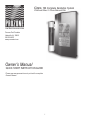
CSS 10 Complete Sanitation System
Ozone/Salt Chlorinator
Prozone Pool Products
Huntsville, AL 35805
256-539-4570
www.prozoneint.com
Owner’s Manual
OPERATING INSTRUCTIONS &
INSTALLATION GUIDE
Introduction…………………………………………………………....…
2
How Does It Work………………………………………………………….
2
Safety Warnings ……………………………………………………………. 2
Parts List ………………………………………………………………….
3
Important Notes ………………………………………………………….
3
Initial Salt Dosage………………………………………………………..
4
Initial Salt Dosage Chart …………………………………………………..
4
Recommended Salt Type and How to Add …………………………….
4
Cell Maintenance……………………………………………………….
4&5
Warranty Information and Form – Please complete and return……
6
Installation Instructions…………………………………………………
7 - 11
Basic Pool Chemistry and Terminology……………………………….
12 & 13
INSTRUCTION MANUAL
1.
2.
3.
4.
Before performing any installation or operation, please read the enclosed instructions carefully.
This manual contains easy to follow step-by-step instructions and procedures to properly install and operate your new system.
The CSS-10 is electrically powered – electrical installation should be by a licensed electrician – ensure all electrical connections are proper
before operating this system.
Taking the time to properly install your new system will insure trouble-free installation and maximum performance.
INTRODUCTION
Congratulations! You have purchased one of the most technologically advanced Pool Sanitation Systems in the world – the Prozone CSS-10
Ozonating/Salt Generator. The cleanest and most powerful solution for Sanitation and Oxidation requirements in your pool, the benefits of which will
be evident from the very first time you use it and for many years to come.
HOW DOES IT WORK
The Prozone CSS-10 Ozone/Salt Generator System is comprised of two basic components: the Ozone System and a Salt Generator Cell. Both are
manufactured to meet stringent safety requirements and are built with corrosion resistant materials (Titanium/Platinum, Aluminum, etc.), to ensure
years of trouble free use in outdoor and indoor environments.
Chlorine Generation with Salt: Chlorine is generated within the Salt Generator Cell by an electrolytic reaction that converts the chlorine in salt to
hypochlorous acid, the useable form of chlorine for swimming pools. Once the initial amount of salt is added, only a small amount will be required
periodically to make up for losses due splashing.
Salt Water: Mild salt water is gentle on the eyes and skin. In seawater the salinity is approximately 35,000ppm (parts per million). The human body
has a salinity of approximately 4,500 to 6,000ppm, while fresh water is at zero. It is the similarity between the salinity of the human body and a pool
Chlorinated with CSS-10 (requires only 2,000ppm), that allows pool owners, and their families, to experience the ultimate in water sanitation, and
“Swimmer Friendly” clean, clear water
Ozone: Chlorine in pools normally reacts with bather loading to form combined chlorines. These combined chlorines are what causes odors,
irritation, and other unpleasant effects that are normally associated with a chlorinated pool. Ozone reacts with these combined chlorines, freeing
the chlorine for reuse and precipitating the contaminants for filtration. This reduces the need for chlorine and results in the cleanest, clearest water
available.
··
··
·
·
·
SAFETY WARNINGS AND GUIDELINES
FAILURE TO ADHERE TO THESES GUIDELINES WILL VOID WARRANTY
DO NOT ATTEMPT TO OPEN THE CSS-10 HOUSING. IT IS NOT A SERVICEABLE UNIT.
FOLLOW ALL INSTRUCTIONS AND FIGURES/DIAGRAMS.
DISCONNECT ALL POWER BEFORE INSTALLATION.
THE CSS POWER SUPPLY MUST BE MOUNTED VERTICALLY ON A FLAT SURFACE AND A MINIMUM OF 5 FEET FROM THE POOL
OBEY ALL LOCAL AND NATIONAL REGULATORY GUIDELINES PERTAINING TO ELECTRICAL AND POOL EQUIPMENT I
NSTALLATION AND USE.
CANADA AND SOME OTHER REGIONAL LOCAL CODES MANDATE THE USE OF GFCI PROTECTED CIRCUITS. IF INSTALLATION
IS COMPLETED BY A LICENSED ELECTRICIAN OR POOL EQIPMENT INSTALLER, THEY WILL BE REQUIRED TO VERIFY THIS
REQUIREMENT FOR YOUR AREA AND COMPLY DURING INSTALLATION.
THE GFCI SHOULD BE TESTED ON A REGULAR BASIS BY PUSHING THE TEST BUTTON ON THE FACE PLATE. IF FOUND FAULTY
REPLACE AND RETEST. DO NOT USE THE SYSTEM WHEN FAULTY.
2
PARTS LISTING
Description
Part Number
Number in kit
CSS10 Box
Salt Generator Bracket
Salt Generator Cell
Saddle Clamp Assembly
Injector
Plastic Clamp (black)
¾” Metal Hose clamp
¼” Braided Hose
¼” Braided Hose
(Cell Maintenance)
¾” Clear Hose
Check Valve (1/4” by ¼”)
White ½” by 3” PVC Pipe
Gasket, Saddle Clamp
Gasket, Saddle Clamp, Barb
Gasket, Saddle Foot
7S10T-42IA-P19
202199
600211
201155
600002
20185
20067
20260
1
1
1
2
1
4
4
120 inches
20260
20264
20214
20314
400078
400076
400018
24 inches
120 inches
1
1
2
2
4
ADDITIONAL SAFETY INSTRUCTIONS
NOTE: When the Pump system is shut down you must also shut down the Salt Generator System.
1.
2.
3.
4.
Your CSS-10 must be installed in accordance with the installation instructions and the Figures/Diagrams provided in this manual.
To have both your Pump system, and the CSS-10 operate properly together as a unit you should wire the two systems together.
The Salt Cell MUST be mounted vertically.
Use only the power cord (DC Voltage) provided with the Ozonator/Salt Generator System to power up the Salt Cell.
IMPORTANT NOTES:
Salt Level Testing:
1. You should test the salt level of your pool before calculating the salt requirement.
2. If a Salt test is not performed you may find later that too much salt will have been added - the Chlorinator may not perform as intended.
3. If the pool has been treated with other forms of Chlorine – for instance Sodium Chloride – you may already have salt content
General:
1. Always balance the pH, total Alkalinity and Calcium hardness, otherwise corrosive or scaly conditions may result, which will lead to equipment
inefficiency or damage. Unbalanced water may cause staining and mineral deposits, chlorine effectiveness may decrease, and bathers may
experience discomfort.
2. Regular testing of the pool waters is recommended. A Free Chlorine level of 0.5ppm (parts per million) to 1.5ppm should be maintained.
3. DO NOT USE Copper or Bromine based Algaecide products in your pool when the CSS-10 is installed.
4. Prozone recommends the pool pump and Salt Generator (see safety note above), for a minimum of 8 to 12 hours a day. Actual run time
will be affected by the chlorine demand from the environment or bathers.
7. WARNING: Always disconnect automatic pool cleaners before adding salt which must be fully dissolved before turning on the
pool cleaner.
8. Plaster Pools: Do not start system until plaster has set for two weeks.
9. WARNING: Baquacil (Biguanide Pools) must be drained and refilled with fresh water prior to using the CSS-10.
10. Read the entire Owner’s Manual. Additional advice can be obtained from a pool installation professional or from a Prozone sales representative
([email protected]) or visit our website at www.prozoneint.com.
3
INITIAL SALT DOSAGE
Maintain a salinity level of 2,000 ppm to 2,500 ppm. Refer to chart below. Pool gallons can be determined from the following formulas:
a. Rectangular – Length x Width x Average Depth x 7.5 (for gallons) or 1000 for liters.
b. Round – Diameter x Average depth x 5.9 (for gallons) or 785 for liters.
c. Oval – Length x Width x Average Depth x 6.7 (for gallons) or 893 for liters.
Salt ppm
Pool Size in Gallons
1,500
2,000
2,200
2,400
2,600
2,800
3,000
8,000 Gallons
10,000 Gallons
12,000 Gallons
14,000 Gallons
16,000 Gallons
18,000 Gallons
20,000 Gallons
24,000 Gallons
26,000 Gallons
28,000 Gallons
30,000 Gallons
32,000 Gallons
34,000 Gallons
36,000 Gallons
38,000 Gallons
40,000 Gallons
100
125
150
175
200
225
250
300
325
350
376
401
426
451
476
501
134
167
200
234
267
300
334
401
434
467
501
534
567
601
634
668
147
184
220
257
294
330
367
441
477
514
551
587
624
661
698
734
160
200
240
280
320
361
401
481
521
561
601
641
681
721
761
801
174
217
260
304
347
391
434
521
564
608
651
694
738
781
824
868
187
234
280
327
374
421
467
561
608
654
701
748
794
841
888
935
200
250
300
350
401
451
501
601
651
701
751
801
851
901
951
1001
RECOMMENDED SALT TYPE AND HOW TO ADD
Type of Salt:
1. Use food grade type of salt (evaporated and granulated) or salt formulated for use with salt chlorine generators.
2. WARNING: Do not use salt that contains ‘Prussiate of Soda’ (Prussiate of Soda is an anti-caking agent which contains iron).
This type salt may cause yellow stains on your pool bottom if left there without being dissolved.
3. WARNING: Do not use ‘rock salt’ which has dirt mixed in with the salt.
4. NOTE: Calcium Chloride is not salt. Use Sodium Chloride only.
5. Water softener salt pellets (Sodium Chloride ) may be used but will take longer to dissolve.
Adding Salt:
1.
2.
3.
4.
Never add salt to the ‘skimmer’ box, however the coarse salt granules may cause the pump impeller to seize.
Always disconnect any automatic cleaners before adding salt, and leave them off until all the salt has fully dissolved.
When pouring bags of salt into pool, pour away from skimmer and suction points. Sweep and brush with a pool broom until the salt dissolves
Keep the pump operating during this process.
CELL MAINTENANCE
1. The Salt Cell requires little or no general maintenance.
2 Periodically inspect the Cell plates to ensure that they are clear of foreign matter and other debris.
NOTE: A filtration problem exists (contaminated water is by-passing the filter) if debris is found to have built up around the electrodes and
plates of the Cell and should immediately be corrected.
3. If calcium build-ups form on the electrodes and plates, it may be caused by one of the following:
a)
b)
c)
Low Water Flow through the Cell – Check the hoses and the injector for blockage of water flow.
Poor water Quality - High calcium content, clean cells (see below).
Aged Cell – After 3-5 years loss of plate coatings may decrease the effectiveness of the self-cleaning process. Replace cell.
4
ACID WASH FOR REMOVAL OF CALCIUM DEPOSITS ON CELL PLATES
WARNING: FOR QUALIFIED POOL PROFESSIONALS ONLY
DO NOT ATTEMPT THIS PROCEDURE WITHOUT PROPER TRAINING
CAUTION: USE PROTECTIVE EYE WEAR, GLOVES, AND PROTECTIVE CLOTHING
1.
2.
3.
4.
Turn PUMP OFF and allow water to drain back out of the cell and by-pass system.
Disconnect the ¼” BRAIDED HOSE from the Venturi Injector.
Place a bottle of Muriatic acid close to the Venturi Injector
Attach one end of the two (2) foot ¼ inch BRAIDED HOSE provided to the open port on the Injector, secure with clamp. Put the other end
of the hose in to the container of Muriatic acid.
5. Turn the pump back on for approximately 1 minute or until Salt Cell is filled with acid.
6. Turn the pump off for 15 to 20 minutes to allow the solution to soak the plates.
7. Repeat Steps 5 and 6 above until the calcium build-up is gone.
NOTE: The solution entering the pool will not disturb the pH of the pool’s water.
NOTE: If build-up is not removed, contact your local dealer or Prozone for additional advice.
8. Reconnect VENTURI to system.
9. Turn PUMP ON.
WINTERIZATION
Freezing water may damage the Cell’s internal components and may cause cracks in the casing , voiding the Warranty. If severe, or extended
periods of freezing temperatures are possible, drain all the water from the pump, filter, Salt Cell, supply and return lines before freezing occurs.
SPRING START-UP
Balance your pool and perform start-up as listed in this manual.
5
WARRANTY
Conditions:
The system carries a complete two (2) year warranty against manufacturing defects.
1. On site labor, service calls or freight charges are the responsibility of the purchaser. Under no circumstances shall the manufacturer be liable for
incidental or consequential damages, inconveniences or expenses in connection with removal or replacement of equipment.
2. Under no circumstances shall the manufacturer be liable for damages caused to persons, or property, as a result of use of this equipment.
The Following Invalidates the Warranty:
1. Incorrect installation.
2. Misuse or abuse
3. Failure to inspect the cell on a regular basis.
4. Cell is used for any other purpose than described herein.
5. Operating the Cell at a pressures exceeding 30 psig.
6. Operating the cell at salt levels lower or higher than
recommended
7. Failure to winterize system.
PROZONE WARRANTY
PLEASE COMPLETE THIS WARRANTY ON THE DAY OF INSTALLATION AND RETURN TO:
PROZONE POOL PRODUCTS INC. , 2610 6TH STREET, SUITE ‘A’, HUNTSVILLE, AL. 35805
Date
of purchase:
__________________________________________________________________________________________________
Purchased
from:
__________________________________________________________________________________________________
Model
Number:
__________________________________________________________________________________________________
Supplier
telephone No.
__________________________________________________________________________________________________
Date
of installation:
__________________________________________________________________________________________________
Installed
by:
__________________________________________________________________________________________________
Name
of purchaser:
__________________________________________________________________________________________________
Address:
__________________________________________________________________________________________________
City:
State:
Zip:
__________________________________________________________________________________________________
Telephone
No.
__________________________________________________________________________________________________
FAX
number:
__________________________________________________________________________________________________
E-mail:
__________________________________________________________________________________________________
Residential
application:
__________________________________________________________________________________________________
__________________________________________________________________________________________________
__________________________________________________________________________________________________
__________________________________________________________________________________________________
6
CSS 10 Complete Sanitation System
Ozone/Salt Chlorinator
Prozone Pool Products
Huntsville, AL 35805
256-539-4570
www.prozoneint.com
Owner’s Manual
QUICK START INSTRUCTION GUIDE
Please see www.prozoneint.com to print out the complete
Owner’s Manual
7
Before installing this product, turn pump off
(Diagram 1) CSS 10 Mounting Instructions
··
·
CSS 10 Power Box
Diagram 1
CSS
Complete Sanitation System
™
Automated System Control
Salt Generator Cell
OZONE SALT/CHLORINATOR SYSTEM
Mount CSS10 in vertical position to a flat surface above the return line to you pool
Position Salt Generator Cell in Mounting bracket attached to bottom of Control Box,
with wire connector leads at bottom
Position loose mounting bracket over top of Salt Generator Cell and fasten to surface with screws
(Diagram 2) ByPass Installation Instructions
·
Diagram 2
Drill 2 holes (use 7/8” hole saw drill bit ) in return line
a. One 7/8” hole between pump and filter
b. One 7/8” hole after filter and heater ( must be last installation going back to pool)
c. This needs to be at lowest point of pressure so water can return to main pipe)
(Diagram 3) Assemble the Saddle Clamp
7/8 inch Hole Saw
(Diagram 4)
··
··
··
7/8 Inch hole
Flow
Attach Saddle Clamp over hole after pump
Insert injector into top of Saddle Clamp, (small ports pointing away
from hole) push injector through Saddle Clamp into hole in return line
Measure and cut ¾” hose to fit distance between injector and bottom of salt cell (View B)
Place two metal clamps on ¾” hose
Attach one end of ¾” hose to top of injector, tighten with metal clamp
Attach other end of ¾” hose to bottom of salt cell, tighten with metal clamp
Diagram 3
CSS
Complete Sanitation System
Spacer for 1 1/2 ” assembly
™
Automated System Control
OZONE SALT/CHLORINATOR SYSTEM
Diagram 4
1 1/2 ” Install only
8
PVC Pipe
Screw (2)
Diagram 5
Washer (2)
Upper Saddle Clamp
Rubber Bushing
1 1/2" Adapter – Upper
Neoprene Gasket
1.5” Saddle Clamp Assembly
7/8" Dia. Hole
Neoprene Gasket
1 1/2" Adapter – Lower
Gasket Foot (2)
Lower Saddle Clamp
(Diagram 5)
Assemble 2nd Saddle Clamp (View C)
(Diagram 6)
Insert 3 inch white PVC pipe into top of Saddle Clamp,
push pipe through Saddle clamp into hole in return line
Place two metal clamps on remaining ¾” hose line
Attach one end of hose to top of Salt Cell, tighten with
metal clamp (View D)
CSS
Complete Sanitation System
Attach other end of ¾” hose to 3 inch PVC pipe,
tighten with metal clamp (View D)
OZONE SALT/CHLORINATOR SYSTEM
Filter
··
··
··
·
™
Automated System Control
(Diagram 7) Ozone System Connection
Return Flow to Pool
Heater
Return Flow to Pool
Diagram 7
Cut 6 inch piece of ¼” braded hose
Attach longer ¼” braded hose to ozone fitting on top of CSS10 Power Box
Secure with black hose clamp
CSS
Insert check valve in other end of longer braided hose,
make sure the air flow is correct (View B)
Complete Sanitation System
™
Automated System Control
OZONE SALT/CHLORINATOR SYSTEM
Attach 6 inch piece of ¼” braided hose to check valve
1/4" Polybraid Hose
from Ozonator to Check Valve
Secure with black hose clamp
Attach end of ¼” braided hose to
open port on top of injector (Diagram 8)
1/4" Check Valve
(See "B")
1/4" Polybraid Hose
from Check Valve to Injector
Injector
Ozo
Water Flow
Diagram 8
Saddle Clamp
&
Injector Assembly
Flow
Pool Return Line after Pump
Open Port
9
Air Flow
ne
Water Flow
..................
·
··
·
Diagram 6
...............
·
2” Saddle Clamp Assembly
Nut (2)
3/4" Clear Vinyl
Bypass Hose
20264 PN
View "B"
·
··
··
(Diagram 9) Electrical System Connection
Connect power lead wires from CSS10 Control Box to matching lead wires
at bottom of salt cell (Diagram 9)
Plug power cord in to power supply
It is recommended to have pump and CSS10 on same timer so that unit is on when pump is running
CSS
Complete Sanitation System
Automated System Control
Turn on Power switch at top of CSS10 Box
You must push in knob and turn clockwise to select chlorine production level (Diagram 10)
OZONE SALT/CHLORINATOR SYSTEM
Diagram 9
Electrical Leads
Diagram 10
Bypass Hose to Pool
Return
Chlorinator Cell
Upper "L" Bracket
Wall
Chlorine Selection Dial
Outlet from Ozonator
to Injector
Power Indicator Light
CSS Unit Viewed From Top
10
™
CSS 10 Unit in Bypass Configuration Shown
Properly Mounted in Vertical Position
L22
L1
PN20264
L21
....
.
....
PN202199
Air Flow
......
L20
PN20260
L2
Cell Electrical Conections
C
SS
Complete Sanitation System
"View A"
™
Automated System Control
OZONE SALT/CHLORINATOR SYSTEM
L3
L19
PN600211
Cell Bottom
PN7510T-42IA-P19
L4
L18
L5
L17
L7
L6
PN20260
PN20214
L16
PN600002
Saddle Clamp Assy.
L13
L1
L12
5
L10
L8
PN20067
PN201155
L9
L14
L11
Diagram A-1
1.
2.
3.
4.
A stream of water is pulled out of the main line through the Venturi Bypass Assembly. (L14)
As water passes through the injector (L15) ozone is being injected through the mixing port of the Venturi Injector (L11)
This water enters the Salt Chlorine Generator Cell through the bottom of the Cell (L18 & L19).
A low voltage DC current is applied to the plates. The electrolysis process transforms this salt water into hyprochlorous acid,
which is your active sanitizer.
5. This sanitized\ozonated water flows out the top of the Chlorine Generator Cell (L22) back in to the main return line (L9)
through the second stage of the Bypass assembly (L7 & L8)
11
WATER CHEMISTRY
CHLORINE PRODUCTION AND CONTROL
Free Chlorine: A ‘free’ Chlorine residual of 0.5ppm to 1.5ppm should be maintained at all times. This will vary only with respect to bathers in the
pool, debris falling into the pool, and the pools overall temperature. These factors will affect the demand for chlorine and also the water ‘balance’ and
‘filtration’ effectiveness (refer to the equipment manufactures specifications with regard to the maximum chlorine level permissible).
Testing for Chlorine: Testing for Chlorine levels is very important and should be performed regularly by the pool owner, as well as a pool water
professional on a periodic basis.
Residual Water Test: The sample of water to be tested should be taken at arms depth away from the pool returns. This will avoid highly chlorinated
water coming from the Salt Generator Cell, and ensures that the reading will be a true representation of the pool’s residual chlorine levels.
Production Water Test: Testing for Chlorine production is performed by taking a sample directly at the pool return, which is water directly from the
Salt Generator Cell, and should indicate a higher chlorine level than the residual test showed.
BASIC POOL CHEMISTRY TERMINOLOGY
TDS – Total Dissolved Solids: There may be other elements, in addition to salt, that may be present in the pool’s water. Your pool professional can
perform a TDS test and determine if there are other elements that may be harmful in the pool water as a result of adding salt.
Combined Chlorine vs. Free Chlorine: Combined Chlorine, which include Chloramines, is a molecule of Chlorine that has attached to a contaminant in the pool water. It remains bound to it until it is the other is burned off through breakpoint chlorination (an unpleasant procedure) or ozonation.
Combined chlorines are most often associated with odors, eye irritation, and other unpleasant side effects of chlorination.
Installation of a Prozone Ozonator/Salt Generator System does away with breakpoint chlorination by
destroying the contaminant particles, and returning the Chlorine to the free state so that it is then able to keep
the pool clean, clear and pleasant to use.
The free Chlorine in your pool is the pure chlorine required to provide residual sanitation at all times and should ideally remain within the range
of .5 to 1.0ppm. This lower level of residual chlorine is possible because your Ozone system has the potential to oxidize and sanitize between
60% and 80% of all the contaminants in the pool’s water. Free chlorine provides a high level of sanitizing power and has no odor or irritating effects.
WATER BALANCE
The water balance of your pool is critical to monitor even after you have installed the CSS-10. There are three components to water balance: pH,
Total Alkalinity; and Calcium Hardness.
pH Level:
1.
2.
3.
4.
5.
6.
7.
8.
pH is a measure of how ‘acidic’ the water is in the pool .
pH is measured on a scale of zero (0) to 14 A level of 7 is considered neutral.
A level greater than 7 is considered alkaline solution, and a level less than 7 is considered acidic.
A high pH (above 7.8) begins to reduce the effectiveness of chlorine, and will potentially cause scale to appear as well as becoming an
irritant to swimmers.
A low pH (les than 7) may cause the water to become corrosive and damage the pools finish, the pool equipment (heat exchangers especially),
as well as becoming an irritant to swimmers.
Each type of pool and pool finish has a specific range in which the pH should remain. Generally, a pH of between 7.2 and 7.8 is suitable for
most pool types and optimum for bather comfort.
To lower pH, a diluted solution of Muriatic Acid is added to the pool.
To raise pH ,add sodium carbonate.
12
Total Alkalinity (TA):
1. The total Alkalinity is a measurement of all the alkalis in your pool water such as Carbonates, Bicarbonates and Hydroxides, and their ability
to resist change in the pH.
2. When adjusted within the acceptable levels, TA acts as a pH buffer, resisting rapid changes to pH. The recommended TA level of your pool
is from 75 to 170ppm depending on the pool finish. A typical level is in the 80 ppm range.
Calcium Hardness:
1. This test is ignored frequently, but is very important for the proper maintenance of your pool.
2. The hardness of your pool water is very important in controlling scale and the corrosive effects of water. A low calcium level may cause pool
water to become corrosive, even if the pH is within its recommended range. A telltale sign of this is a build up of calcium deposits inside
your Chlorine Generator Cell
3. A high calcium level may cause pool water to deposit scale even if the pH is within its recommended range.
4. Generally a level of 50 to 200ppm is recommended, with a level of 100ppm considered ideal.
Nitrates:
There should be no nitrates in your pool water. Most often Nitrates are associated with fertilizers. A high level of nitrates may cause a higher than
normal demand on Chlorine, often lowering the Chlorine level down to zero. This is not a common problem.
NOTE: THE OZONE SYSTEM WILL PRECIPITATE ANY NITRATES.
Metals:
Certain metals may either stain the pool and/or cause chlorine levels to decrease. If testing shows a presence of metals in your pool, consult a pool
professional for methods of removal. OZONE WILL REMOVE IRON AND MANGANESE FROM WATER.
NOTE: THE OZONE SYSTEM WILL PRECIPITATE ANY METALS, HELPING TO SOLVE THIS WATER QUALITY ISSUE
CYANURIC ACID – CHLORINE STABILIZER
1. The sun’s ultraviolet light breaks down the Chlorine in your pool’s water within approximately 2 hours, and therefore the pool’s water content
requires, particularly in sunny climates, the use of Chlorine stabilizers.
2. The Prozone Ozonator/Salt Generator System has been developed to be a chlorine stabilizer, and is sized to be used in accordance with
your pool systems requirements.
3. Either a cyanuric acid system, or the Prozone Ozonator/Salt Generating system, when used in the pool water to achieve levels of between
50 to 80ppm, will effectively reduce the breakdown of Chlorine by UV light.
13