1
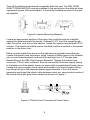
OZONE GENERATORS FOR SPAS INSTALLATION & OPERATIONS MANUAL For Models: SpaECLIPSE, CDS-16, ZO-300, ZO-302, & ZO-301 MANUFACTURED BY San Luis Obispo, CA 93401 4-0581 Rev. A 120601/01 DEL Industries • ONE YEAR LIMITED WARRANTY The limited warranty set forth below applies to products manufactured by DEL INDUSTRIES, 3428 Bullock Lane, San Luis Obispo, California 93401, and sold by DEL INDUSTRIES and its authorized dealers. This limited warranty is given only to the first retail purchaser of such products and is not transferable to any subsequent owners or purchasers of such products. DEL INDUSTRIES warrants that it or its authorized dealers will repair or replace, at its option, any part of such products proven to be defective in materials or workmanship within one (1) year of the date of retail purchase of such products ANY REPAIR OR REPLACEMENT WILL BE WARRANTED ONLY FOR THE BALANCE OF THE ORIGINAL WARRANTY PERIOD. NOTE: USE ONLY DEL AUTHORIZED REPLACEMENT PARTS. USE OF ANY OTHER PART(S) WILL AUTOMATICALLY VOID THIS WARRANTY. THIS LIMITED WARRANTY DOES NOT INCLUDE ANY OF THE FOLLOWING: (a) any labor charges for trouble-shooting, removal, or installation of such parts; (b) any repair or replacement of such parts necessitated by faulty installation, improper maintenance, improper operation, misuse, abuse, negligence, accident, fire, repair materials, and/or unauthorized accessories; (c) any such products installed without regard to required local codes and accepted trade practices; (d) ANY IMPLIED WARRANTY OF MERCHANTABILITY OR IMPLIED WARRANTY OF FITNESS FOR PARTICULAR PURPOSE, AND SUCH WARRANTIES ARE HEREBY DISCLAIMED; AND (e) DEL INDUSTRIES SHALL NOT BE LIABLE UNDER ANY CIRCUMSTANCES FOR LOSS OF USE OF SUCH PRODUCTS, LOST PROFITS, DIRECT DAMAGES, INDIRECT DAMAGES, CONSEQUENTIAL DAMAGES AND/OR INCIDENTAL DAMAGES. This warranty gives you specific legal rights. You may also have other rights which vary from state to state. TO OBTAIN WARRANTY SERVICE: Contact DEL INDUSTRIES, 3428 Bullock Lane, San Luis Obispo, CA 93401 Customer Service Number: (800) 676-1335 x248. When filing a claim, you must provide: 1) your name, mailing address and telephone number; 2) the selling dealer’s name; 3) proof of date of purchase; 4) the date of failure; and 5) a description of the failure. After this information is provided, DEL INDUSTRIES will issue a RETURN GOODS AUTHORIZATION (RGA) NUMBER. After receiving this number, the part in question must be returned to DEL INDUSTRIES, freight prepaid, with the RGA number clearly marked on the outside of the package. All pre-authorized defective parts must be returned to DEL INDUSTRIES within thirty (30) days. Under no circumstances may any product be returned to DEL INDUSTRIES without prior authorization. You must call or write first or your returned goods shipment will be refused. Upon receipt of pre-authorized returned. goods, DEL INDUSTRIES will repair or replace, at DEL’s option, the defective product(s) and return them freight collect. To validate your warranty, fill in the enclosed warranty registration card and return it to DEL INDUSTRIES within ten (10) days of your purchase. Buyer’s acceptance of the product and use thereof constitutes acceptance of these terms. IMPORTANT SAFETY INSTRUCTIONS Proper installation and safe use of your DEL spa ozone generator is your responsibility. Read and follow this Owner’s Manual carefully for important installations, operation and safety information. Basic safety precautions should always be followed, including the following: 1. 2. 3. 4. READ AND FOLLOW ALL INSTRUCTIONS All electrical connections should be made by a qualified electrician. Follow all applicable electrical codes. Be sure all the electrical power is shut off at the main circuit breaker before installing the ozone generator. 5. Connect to a grounded grounding-type receptacle only. 6. If the ozone generator electrical connections will be attached directly to the spa controls, be sure the spa controls are protected by a Ground Fault Circuit Interrupter (G.F.C.I.). If the DEL spa ozone generator is connected to an independent electrical supply, then a G.F.C.I. must be installed between he ozone generator and the electrical supply. 7. A pressure wire connector (ground lug) is provided on the outside of all ZO-300/301/302 ozone generator units to allow the connection of a minimum No. 8 AWG (8.4 mm2) solid bonding conductor (wire) between this point and any metal equipment, metal enclosure of electrical equipment, metal water pipe, or conduit within five (5) feet (1.5m) of the unit, as needed, to comply with local requirements. 8. Do not bury the cord. 9. WARNING: To reduce the risk of electric shock, replace a damaged cord immediately. 10. Per U.L. requirements, the ozone generator must be mounted indoors, or under a cover, sheltered from the natural elements (e.g.: rain, sun, sprinkler). 11. The ozone generator must be mounted above the water line, at least five (5) feet away from the spa and at least one (1) foot above the water level. 12. Mount the ozone generator so that it is inaccessible to anyone in the spa. Never attempt any servicing while wet. 13. To reduce the risk of injury, this unit should be mounted where it is inaccessible to children. 14. Plastic ozone supply tubing is supplied with the ozone generator. Never replace this tubing with metal tubing, as ozone will damage it. 15. Do not operate the ozone generator unless sufficient air flow (~2 scfh) is being drawn through the unit. 16. WARNING: Short term inhalation of high concentrations of ozone and long term inhalations of low concentrations of ozone can cause serious harmful physiological effects. Do not directly inhale ozone gas produced by this device (i.e. do not inhale directly from tubing or ozone generator). SAVE THESE INSTRUCTIONS. 1 TABLE OF CONTENTS Important Safety Instructions .............................................................. 1 Table of Contents ................................................................................ 2 How The DEL Spa Ozone Generator Works ........................................ 3 Installation Parts ................................................................................. 3 Tools and Materials ............................................................................. 3 Unit Assembly .................................................................................... 3 Installation Mounting ....................................................................................... 4 Ozone Supply Tubing Connection.................................................. 4 “Ozone Ready” Spas ..................................................................... 5 Installation for location A&B ................................................... 5 Plastic Hose Connector ................................................................ 7 Saddle Clamp Assembly .............................................................. 7 Installation for location C ........................................................ 8 Installation for location D ........................................................ 8 Installation for location E ........................................................ 10 Electrical Connection .................................................................... 10 DEL Suction Test .......................................................................... 10 Failed DEL Suction Test ................................................................ 11 Hartford Loop Installation .............................................................. 11 Final Check ......................................................................................... 11 Maintenance ....................................................................................... 12 Replacing the Ozone Chip/ UV Lamp Cartridge ................................... 12 Parts List ............................................................................................ 14 Trouble Shooting ................................................................................. 15 2 HOW THE DEL SPA OZONE GENERATOR WORKS Ozone is introduced to the spa water through suction created by the spa. The tubing that is attached to the ozone generator is connected to the spa via an injector or to a port labeled “ozone” by the spa manufacturer. When your system comes on in the water filtration mode, water travelling through the venturi injector creates a vacuum that pulls the ozone out of the ozone generator and injects it into the water. At no time does water come in contact with the ozone generator. When your filtration system is in the off mode gravity may cause water to travel back in the tubing towards the ozone generator. To prevent water from reaching the ozone generator, a one-way check valve must be installed in the tubing. This check valve only allows the flow to go one way from the ozone generator to the injector. To further prevent water from backing up into the ozone generator, form a “Hartford” loop in the ozone supply tubing and hang the loop as high as possible in relation to your spa’s water level (see pages 8 & 11). INSTALLATION PARTS All models: (1) manual, (5’) ozone supply tubing, (2) screws (1) ozone supply check valve, (4) gold hose clamps ZO-300, 302, 301: (2) mounting clips TOOLS AND MATERIALS NEEDED FOR INSTALLATION PVC Cement Electrical Drill Screwdriver PCD Tee (optional) Hacksaw or PVC Hose Cutter Teflon Tape or Thread Sealant Tape Measure UNIT ASSEMBLY The SpaECLIPSE, CDS-16 and ZO-301 are supplied pre-assembled. To assemble the ZO-300 & ZO-302, refer to Figure 1 below and the instructions on the following page. ZO-301 ZO-300/302 Figure 1: ZO-300/302, ZO-301 & SpaECLIPSE 3 SpaECLIPSE (or CDS-16) Connecting ZO-300/302: Insert lamp cartridge straight into power supply, being careful to align pins, and bonding plate (on back). Press power supply and lamp cartridge together. CAUTION: DO NOT TWIST cartridges while pushing them together. Twisting will damage the OZONE GENERATOR which could lead to premature failure. Attach the two cartridges by securing the bonding plate to the lamp cartridge. Use the included self-tapping screw and star washer. INSTALLATION MOUNTING Find a suitable location to mount the ozone generator. To prevent water from backing up into the ozone generator, it should be secured one (1) foot above the spa’s water level and at least five (5) feet away from the water, out of arm’s reach. Locate the unit so that electrical and ozone supply tubing connections can be made easily. The ozone generator must be mounted indoors or under a cover, protected from natural elements. The unit may be mounted under the spa’s skirt by utilizing a Hartford Loop (see page 11). NOTE: If the ozone generator is used on an indoor spa, the room needs to have adequate ventilation. SpaECLIPSE/CDS-16: Attach the unit to a solid surface using screws (included). ZO-300/320/301: The recommended mounting direction is with the tube horizontal; however, it may be mounted vertically, with the power cord up. Attach the mounting clamps to a solid surface with screws provided. Snap the generator into the mounting clips by inserting one leg first and then rotating the unit until it locks into place. Each clip should be centered on a cartridge. OZONE SUPPLY TUBING Your ozone generator includes 5’ of tubing. Cut the tubing 4’ from the ozone generator. Insert the check valve between the cut to reconnect the pieces. The check valve permits ozone to flow through in one direction while preventing water from backing up into the ozone generator. You can test the direction by blowing through one end of the check valve (air will only flow through from one end). There are various locations to which the other end of the ozone supply tubing can be connected to a spa that is not ozone ready. Review the following section to determine which location is most suitable. 4 OZONE SUPPLY TUBING CONNECTION LOCATIONS: OZONE-READY SPAS If your spa is factory equipped with an ozone injection point, follow the manufacturer’s installation instructions. Check with your dealer. After installation, you will need to test the suction at the injection point. Refer to the section titled “DEL Suction Test” for instructions on performing this test. NON OZONE-READY SPAS: LOCATION “A” & “B” (see Figures 2 & 3): These are the most common connection locations. The assembly procedures are the easiest and sufficient ozone dispersion is provided. They can be used if the air control valves completely close. LOCATION “C” (see Figure 2): This location is used if the air control valve does not have a defined closed position. LOCATION “D” (see Figure 5): This connection procedure is used on spas which have a two-speed pump and where the venturi air line is inaccessible or will not provide sufficient suction to operate the ozone generator properly. A DEL RIGID INJECTOR MANIFOLD (DEL Part Number IU-201) is required and can be ordered from your local dealer. This connection is also used if an air blower is provided to “supercharge” the jets. LOCATION “E” (see Figure 5): Use this location on spas with a single-speed pump. A DEL ADJUSTABLE INJECTOR MANIFOLD (DEL Part Number IU206) is required and can be ordered from your local dealer. Locations “D” and “E” provide the most efficient method for dispersing ozone into the spa’s water. OZONE SUPPLY TUBING CONNECTION: Once a suitable location has been chosen, follow the appropriate connection instructions below. LOCATIONS “A”, “B”, “C”: NOTE: In the case where there are two air control valves, it may be helpful to determine which one has the best air suction. To do this, operate the pump on low speed with both air control valves open. Observe the action of the jets. The lowest jet with the most bubbles will suggest the best location in the air venturi line for the ozone supply tubing connection. 5 INSTALLATION FOR LOCATIONS “A” & “B”: Turn off the electrical power and drain the spa at least 12 inches below the selected “A” (Figure 2) or “B” (Figure 3) location. The installation instruction for locations “A” & “B” are identical except that location “A” utilizes a vertical air venturi line and location “B” utilizes a horizontal air venturi line. Use the spa’s venturi air line which provides the best suction and is connected to the lowest jet. (See NOTE on page 5). NOTE: The saddle clamp assembly (Figure 4) may be used if the spa is plumbed with rigid PVC pipe or if there are any rigid locations on the air venturi line such as a tee or elbow fitting. Saddle clamps can be ordered through your local dealer using DEL part number 9-0001. If the spa is plumbed with flexible PVC pipe, an appropriately sized PVC tee fitting, with the center having 1/2” female threads (not included) must be installed (see Figure 3). The plastic hose connector threads into the tee fitting. Figure 2: Vertical Air Venturi Line (Location “A”) Figure 3: Horizontal Air Venturi Line (Location “B”) 6 PLASTIC HOSE CONNECTOR INSTALLATION: A plastic hose connector installed onto the air venturi line may be used when the spa is not “ozone ready”. The plastic hose connector can be purchased from your dealer using DEL part number 7-0127 (see Figure 7). Select a convenient location, that provides enough room to work, to install the PVC tee fitting with 1/2” female threads (not included). Cut the existing air venturi line at the selected “A” or “B” location (see Figures 2 & 3). Glue the fitting into place. Be sure to use “FLEX-TO-RIGID” PVC Cement. Wrap Teflon tape on the plastic hose connector threads and install into the tee fitting. SADDLE CLAMP ASSEMBLY INSTALLATION: If no other installation location is available on your spa, a saddle clamp assembly can be utilized. Please contact your local dealer to order DEL part number 9-0001. To use the saddle clamp assembly, find a suitable location to secure it. Possible locations are shown in Figure 4. Be sure the chosen location is part of the air venturi system and that there is enough clearance to tightly secure the saddle clamp. Drill a 3/8” diameter hole at the chosen location. BE CAREFUL not to drill through the back of the pipe or fitting. Push the nipple into the hole and secure by tightening down the saddle clamp. Connect the 5’ of tubing with check valve installed to the ozone generator cartridge. Connect the other end of the tubing to the saddle clamp assembly nipple. See ELECTRICAL CONNECTION to complete installation. Fully close the air control valve to provide maximum suction. If the spa is equipped with adjustable jets be sure that they are all completely open. When final electrical connections have been made, fill the spa to its normal operating level and turn the power back on. Proceed to the DEL SUCTION TEST section before final connection of ozone supply tubing is made. Figure 4: Possible Saddle Clamp Locations 7 INSTALLATION FOR LOCATION “C”: Turn off the electrical power and drain the spa at least 12 inches below the air venturi line which provides the best suction and is connected to the lowest jet. Cut the PVC flex tube approximately 3” to 4” from the air control valve. Install an appropriately sized PVC reducer fitting (not included), with 1/2” female threads on one end. Be sure to use FLEX-TO-RIGID- PVC Cement whenever working with PVC flex tubing. Wrap Teflon tape on the plastic hose connector threads and install into the reducer fitting, securing ozone supply tubing. This entire assembly should be secured as close to the top of the spa waterline as possible. NOTE: This installation will cause ozone to be drawn only through the jet(s) dedicated to this venturi air line no matter what position the air control valve is in. Attach the 5’ of tubing with check valve installed to the ozone generator cartridge. Be sure the check valve bevel is pointed towards the spa and away from the ozone generator. See ELECTRICAL CONNECTION to complete installation. When final electrical connections have been made, fill the spa to its normal operating level and turn the power back on. Proceed to the DEL SUCTION TEST section before final connection of ozone supply tubing is made. INSTALLATION FOR LOCATION “D” (TWO-SPEED PUMPS): For the location “D” connection, a DEL RIGID INJECTOR MANIFOLD (DEL Part Number IU-201) is required - contact your local dealer (See Figure 5). Figure 5: DEL Injector Manifold Installation Diagram 8 Turn off the electrical power and completely drain the spa. The DEL RIGID INJECTOR MANIFOLD must be installed in the spa’s return line after all other equipment (pump, filter and heater). It should be installed as close to the spa as possible. Figure 6: Injector Mounting Diagram Locate an appropriate section of the return line, hold the injector manifold against the pipe and mark the length. Subtract 2-2/3” from the overall length, mark this point, and cut out the section. Install the injector manifold with PVC cement. The injector manifold can be installed in either a vertical or horizontal position in the return line. Make sure the water flow arrow on the ball valve is pointed toward the spa. Locate the plastic hose connector, wrap 3 layers of teflon tape on the threads (do not use thread sealant), and install it hand tight into 1/2” female pipe thread fitting of the DEL Rigid Injector Manifold. Tighten the plastic hose connector 1/2 turn with a wrench. Secure one end of the ozone supply tubing to the barb end of the plastic hose connector with a supplied gold hose clamp. Locate the ozone supply check valve and install it into ozone supply tubing by cutting tubing in two separate places approximately 4’ from the ozone generator and insert the check valve between each cut, securing both ends of the check valve with gold hose clamps as shown in Figure 7. Figure 7: Plastic Hose Connector & Check Valve 9 Attach the check valve assembly to the ozone generator cartridge. Be sure the check valve bevels are pointed towards the spa and away from the DELZONE unit - you should be able to blow air through the tubing in one direction. See ELECTRICAL CONNECTION to complete installation. When the final electrical connections are completed, refill the spa to its normal operating level (check for leaks as the spa is filling), and turn the power back on. Proceed to the DEL SUCTION TEST section before final connections of ozone supply tubing are made. INSTALLATION FOR LOCATION “E” (SINGLE-SPEED PUMPS) For the location “E” connection, a DEL ADJUSTABLE INJECTOR MANIFOLD (DEL Part Number IU-206) is required. The injector manifold must be installed on the spa return line after all the spa equipment (See Figure 5). Refer to the instructions for installing a DEL RIGID INJECTOR MANIFOLD, Installation for Location “D”, above. ELECTRICAL CONNECTION The electrical cord should be wired to the pump controller so that the generator comes on only when the pump is on (for two speed pumps the generator should be wired to the low speed control). Ozone generators supplied with a special plug should be connected to the appropriate electrical outlet on the spa pack on ozone-ready spas. Some units require the addition of a minimum 8 AWG grounding wire, to comply with local requirements. This wire must be connected from the open ground lug of the power supply cartridge to a grounding point. DEL SUCTION TEST The DEL suction test is used to determine if the selected venturi location will provide enough suction for proper ozonation of the spa, and for setting the position of the ball valve on the DEL adjustable injector manifold in location “E”. To test the suction, disconnect the ozone supply tubing from the ozone generator. With the spa running, place your thumb over the end of the tubing and check how much suction is applied to your thumb. The suction should be strong enough to lightly “suck” your thumb to the end of the tubing. 10 FAILED DEL SUCTION TEST Very little or no suction may be caused by the list of possible problems below. Review the list then test for suction again. 1. Dirty filter: Clean the filter and test again 2. Clogged jets: Clean and test again 3. Closed adjustable jets: Open completely and test again 4. Jet nozzle orifices too small: Remove orifice reducers or drill larger orifices. 5. Injector Manifold installed before heater or pump: All Injector Manifolds must be installed AFTER all spa support equipment. Failure to do this will result in poor suction as well as damaged equipment. 6. Spa pump sized either too large or too small for number or sizes of jets located in spa. HARTFORD LOOP INSTALLATION Make a loop with the ozone supply tubing and secure it above (or as close to) the spa water level. This loop will prevent water from backing up into the ozone generator should the check valve fail. A Hartford Loop must be installed to validate the warranty. If a single loop cannot be secured above the water line, make two complete eight (8) inch diameter loops with the ozone supply tubing and secure as high as possible. FINAL CHECK Recheck the ozone generator installation. Be sure all electrical connections are correct, the unit is mounted properly and the ozone supply tubing is connected. When the spa’s pump comes on, a blue glow from the ozone chip (SpaECLIPSE/CDS-16) or a blue glow on the ends of the lamp cartridge (ZO300/301/302) indicate that the ozone generator is working properly. NOTE: When the ZO-300/301/302 is turned on, it is normal for the light to hesitate a few seconds before it activates. If your supply voltage drops below 110V, it could take a longer time for the ozone generator to start. Cold weather may also affect starting time. 11 The spa’s mechanical system will run exactly as before. Note: If the pump is above the water level of the spa and there is not a flapper valve in the strainer basket housing, the pump may lose its prime on an injector installation. Most pump/filter systems have this valve. If yours does not, add a DEL CHECK 1/3# check valve (DEL part number C0-0101, not included) between the spa outlet and the strainer basket housing. Continue to follow the instructions for the pump, filter, heater, etc., that come with your spa. Once the ozone generator is functioning properly, there is nothing the spa owner must do to operate it. It should be hooked up so that it operates automatically with the spa system. If it does not, refer back to the electrical section. MAINTENANCE A blue glow indicates that the SpaECLIPSE/CDS-16 ozone chip or ZO-300/ 302/301 UV lamp is working. The ozone chip and lamp cartridge both have a life expectancy of about 9,000 hours. They will need to be replaced every two to three years under normal operation. If you suspect a problem, call the DEL Ozone Hotline at 1-800-676-1335. REPLACING THE OZONE CHIP (SpaECLIPSE/CDS-16) 1. 2. 3. 4. 5. 6. 7. 8. 9. 10. 11. 12. Turn off the electrical power. Remove the SpaECLIPSE/CDS-16 from its mounting location. Remove the ozone supply tubing from the generator. Remove the three screws from the back of the unit (see Figure 9, page 13). Remove the base from the unit. Tug the wires connected to the ozone chip to remove it from its housing. Disconnect the high voltage connectors and power connector by pulling them apart - be sure to note how the wires were connected. NOTE: Only pull on the hard, white plastic wire connectors. Do NOT pull on the wires. Discard the old ozone chip. Connect the new ozone chip and push it into its housing so that the white portion shows through the viewing window on the front of the unit. Replace the base of the unit and tighten the three screws. Attach the ozone supply tubing to the ozone outlet. Re-install unit on spa, reconnect the ozone supply tubing and reconnect the power cord. 12 Figure 9: SpaECLIPSE/CDS-16 Ozone Chip Replacement REPLACING THE LAMP CARTRIDGE (ZO-300/302) 1. 2. 3. 4. 5. Turn off the electrical power. Remove the ozone generator from the holding clamps. Remove the ozone supply tubing from the generator cartridge. Loosen the bonding plate screw. Remove the lamp cartridge by gently pulling the ozone generator apart to separate the cartridges. Wiggling the cartridges slightly will help separate them. CAUTION: DO NOT TWIST the cartridges while separating. Twisting will damage the OZONE GENERATOR and may lead to premature failure. 6. Installation of the new lamp cartridge is accomplished by reversing the above procedure. Be careful to align the pins properly. Refer to UNIT ASSEMBLY at the beginning of this manual. REPLACING THE LAMP CARTRIDGE (ZO-301) The ZO-301 is a one-piece, disposable ozone generator. Following 9,000 hours of operation, it is should be replaced with a new generator. 13 SpaECLIPSE/CDS-16 REPLACEMENT PARTS LIST DESCRIPTION PART NUMBER DEL RIGID INJECTOR MANIFOLD (for 2-speed pump) .................. IU-201 DEL ADJUSTABLE INJECTOR MANIFOLD (for single-speed pump) ....... IU-206 REPLACEMENT OZONE CHIP ...................................................... 5-0561 OZONE SUPPLY CHECK VALVE ................................................... 7-4012 OZONE SUPPLY TUBING .............................................................. 7-0075 GOLD HOSE CLAMP ..................................................................... 2-0078 PLASTIC HOSE CONNECTOR (not included with unit) ................... 7-0127 SADDLE CLAMP ASSEMBLY (not included with unit) .................... 9-0001 ZO-300/302 REPLACEMENT PARTS LIST DESCRIPTION PART NUMBER DEL RIGID INJECTOR MANIFOLD (for 2-speed pump) .................. IU-201 DEL ADJUSTABLE INJECTOR MANIFOLD (for single-speed pump) ....... IU-206 REPLACEMENT GENERATOR CARTRIDGE ................................. 9-0362 OZONE SUPPLY CHECK VALVE ................................................... 7-4012 OZONE SUPPLY TUBING .............................................................. 7-0075 GOLD HOSE CLAMP ..................................................................... 2-0078 PLASTIC HOSE CONNECTOR (not included with unit) ................... 7-0127 SADDLE CLAMP ASSEMBLY (not included with unit) .................... 9-0001 14 TROUBLE SHOOTING SYMPTOM: No blue light glowing in chip or lamp cartridge PROBABLE CAUSE CORRECTIVE ACTION 1. No power to unit 1A. Check power source and cord 2. Broken or defective 2A. Replace chip or lamp cartridge chip or lamp cartridge 3. Defective power supply 3A. Return to dealer for warranty cartridge (ZO-300/302) replacement SYMPTOM: Blue light glowing but no ozone smell on water surface PROBABLE CAUSE CORRECTIVE ACTION 1. Ozone is present but smell 1A. Do not add any more chemicals for 24 is obscured by other chemhours, then recheck icals in the water 2. Open or leaking air control 2A. Remove air control cap and check valve (venturi installation) condition of “O” ring - if o-ring is deteriorated, replace and tighten cap snugly 3. Lack of suction to ozone 3A. See 2A supply tubing (venturi 3B. Check for dirty filter or incorrectly injector installation only) operating pump 3C. Check adjustable jets and open completely 3D. Check for debris in jets 3E. Check ozone supply tubing check valve 3F. Check if blower is connected to the air venturi line. This situation requires an injector assembly. 4. Lack of suction to ozone 4A. See 3B-3E supply tubing (injector 4B. Jets may need to be sized larger system only) SYMPTOM: Cloudy water condition even though the unit appears to be operating properly PROBABLE CAUSE CORRECTIVE ACTION 1. Unit and pump not operating 1A. Increase operating time (min. 6 hours long enough is recommended) 2. Total alkalinity not correct 2A. Adjust total alkalinity betw. 80-150 ppm 3. pH not correctly balanced 3A. Check for proper pH betw. 7.2-7.6 4. Not enough suction 4A. Perform DEL Suction Test. Remove air control cap and check condition of “O” ring - replace and tighten cap snugly 15 5. Too much suction 5A. Adjust the jets to reduce suction 6. Dirty, loose, cracked filter 6A. Check/replace filter as needed 7. Metals or minerals in water 7A. Ozone may react with metals/minerals in the water (this is common when new water is added) causing cloudy water. Check alkalinity, pH, and clean filter. Run filtration system and ozone for 24 hours and clean filter. SYMPTOM: Pump loses prime when system is off PROBABLE CAUSE CORRECTIVE ACTION 1. No flapper valve in pump 1A. Add flapper valve strainer SYMPTOM: System on/off – water backing into ozonator When your system is in its “on” cycle a suction of air is being pulled through the tubing from the ozonator to the return line. As the air passes by the ozone chip or the ozone lamp, the oxygen in the air is converted to ozone. This ozonated air is introduced to the water via the venturi on your return line. When the system is in its “off” cycle water tends to flow back in the tubing towards the ozonator. Therefore, mounting your ozone unit as high as possible in relation to the spa water level is important. There is also a oneway check valve provided to prevent the back flow of water from reaching the ozonator. As a secondary precaution, a Hartford loop in the tubing, also hanging above water level, will help prevent water damage to the ozonator (see pg. 6, Fig. 2). 16 Copyright DEL Industries 1999