1
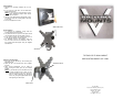
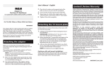
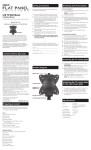
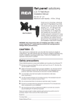
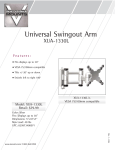
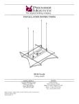
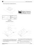
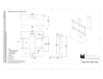
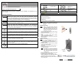
Included Hardware
INSTALLATION GUIDE: XUT-1330L
Victory LCD Wall Mounting System
The Victory LCD Mounting System is designed for secure installation of LCD displays of up to
40 lbs. in weight.
Warning Statements
WARNING: THE WALL STRUCTURE MUST BE CAPABLE OF SUPPORTING AT LEAST A MAXIMUM
WEIGHT OF 40 LBS. IF NOT, THE WALL MUST BE REINFORCED. PROPER
INSTALLATION PROCEDURE BY A QUALIFIED SERVICE TECHNICIAN, AS OUTLINED IN
THE INSTALLATION INSTRUCTIONS, MUST BE ADHERED TO. FAILURE TO DO SO
COULD RESULT IN SERIOUS PERSONAL INJURY OR EVEN DEATH.
WARNING: SAFETY MEASURES MUST BE PRACTICED AT ALL TIMES DURING THE INSTALLATION
OF THIS PRODUCT. USE PROPER SAFETY GEAR AND TOOLS FOR THE INSTALLATION
PROCEDURE TO PREVENT PERSONAL INJURY.
WARNING: PRIOR TO THE INSTALLATION OF THIS PRODUCT, THE INSTALLATION INSTRUCTIONS
SHOULD BE READ AND COMPLETELY UNDERSTOOD. THE INSTALLATION
INSTRUCTIONS MUST BE READ TO PREVENT PERSONAL INJURY AND PROPERTY
DAMAGE. KEEP THESE INSTALLATION INSTRUCTIONS IN AN EASILY ACCESSIBLE
LOCATION FOR FUTURE REFERENCE.
A secure structure must support the weight or load of the display. When mounting to a wall that
contains wooden studs, dead center of the wooden stud must be confirmed prior to installation.
Do not install on a structure that is prone to vibration, movement or chance of impact. Failure to
do so could result in damage to the display and/or damage to the mounting surface.
Do not install near heater, fireplace, direct sunlight, air conditioning or any other source of direct
heat energy. Failure to do so may result in damage to the display and could increase the risk of
fire.
At least two qualified people should perform the installation procedure. Injury and/or damage
can result from dropping or mishandling the display.
Recommended mounting surfaces: wooden studs and solid-flat concrete. If the mount is to be
installed on any surface other than wooden studs, use suitable hardware (which is
commercially available).
Contact Victory Mounts with any technical / installation questions.
¾” Spacer (Qty 4)
M4 x 12mm Phillips
Head Screw
(Qty 4)
2” Wood Screw
(Qty 2)
M4 x 30mm Phillips
Head Screw
(Qty 4)
Bubble Level (Qty 1)
Tool List
Phillips Head Screw Driver
Electronic Stud Finder
Allen Wrenches (supplied)
Portable Drill
¼” Masonry Bit for Concrete Installation
NOTE: The included level may be permanently
attached to the wall plate by inserting the
level into the receptacle on the back of the
wall plate.
Wood Stud Installation
NOTE:
Using a wood stud finder, locate the
stud centers behind the wall. Once found,
make a pencil marking on the center of the
wood studs. Once the mark is made, it is
strongly recommended that a pilot hole be
drilled with a 1/8” drill bit.
1. Place the back plate against the wall with the
hook towards the bottom.
2. Secure the back plate using one (1) 2” wood
screw.
3. Using the integrated bubble guide, carefully
adjust the back plate until it is level.
4. Attach the remaining 2” wood screw into the back
plate and tighten.
Concrete Installation
NOTE: ¼” x 2 ¼” Threshold anchors must be used
for concrete installation. They can be
purchased at your local hardware store.
1. Place the back plate against the wall with the hook
towards the bottom.
2. Level and mark with a pencil the two mounting
points found on the back plate.
3. Next, drill two holes using an electric drill and ¼”
masonry bit.
4. Insert the threshold anchors into the holes that
were drilled in the wall.
NOTE: If necessary, use a hammer to lightly tap
each anchor into place so that they are
flush with the wall. Once mounted in the
wall, unscrew the slotted cap off of the
threaded insert.
5. Once the anchors are in place, set the back
plate back over the concrete anchors.
6. Using a Slot Head screw driver, attach the back
plate by threading the two slotted caps onto the
threaded insert that is recessed into the wall.
7. Make sure all screws are snug, but be careful not
to over-tighten them.
Threshold
Threshold
Anchor
Anchor
Slotted Cap
Threaded Insert
Threshold Anchor
LCD Installation
1. Determine the mounting hardware that is to be
used.
2. If your LCD has a flat back, use the M4x12mm
Phillips Head Screws.
NOTE: If your LCD has a recessed back, use the
longer M4x30mm Phillips Head Screws
and 3/4” Spacers.
3. After you have determined the appropriate screws,
use them to attach the mounting plate to the back
of your LCD.
4. Do not over-tighten the screws.
Slide Plate Down
Final Installation
1. To complete the installation, simply slide the
mounting plate onto the back plate.
2. The plastic tab on the top of the back plate should
click, indicating that the mounting plate is secure.
3. If you need to remove the mounting plate, push in
on the tab and slide the mounting plate up.
4. For additional security and stability, insert the
hex set screw into the hole located on base of
the mounting plate and tighten using the supplied
Allen Wrench.
Set Screw
TILTING LCD TV WALL MOUNT
Operation and Adjustment
1. Tilt angle can be adjusted by first loosening the
adjustment knob.
2. Adjust the tilt to the desired level and re-tighten
the knob.
3. Other viewing adjustments can be made by
simply moving the elbow joint into the desired
position.
NOTE: If you find that a joint is too difficult to move
or does not hold the LCD in place, you can
adjust the tightness of the joint. This can be
done by either tightening the adjustment
knob, or by using the supplied Allen wrench
and tightening the elbow joint.
INSTALLATION GUIDE: XUT-1330L
Adjustment Knob
Elbow Joint
Produced By:
Progressive Marketing Products, Inc.
3130 E. Miraloma Ave.
Anaheim, CA 92806
800-368-9700
[email protected]