1
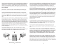
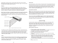
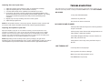
Mobile Audio Electronics
CONGRATULATIONS AND THANK YOU for your choice of a
PrecisionPower, Inc. high performance mobile audio amplifier.
PrecisionPower is proud to be a world leader specializing in the
design, engineering, and manufacture of "State of the Art" mobile
audio electronics. Our success is derived from the fact that we do not
incorporate gadgets or passing fads into our products. Sound
engineering practice, combined with deceptively simple yet highly
effective circuit designs, characterize every PPI product. Yet, our
demand for maximum value dictates that every ounce of fat be
trimmed if it does not contribute to sound quality or reliability. This is
why PPI products have consistently enjoyed an unparalleled
reputation for sound value. We are sure that your new Art Series
amplifier will provide you the "State of the Art" in mobile audio
amplification.
Table of Contents
Important Safeguards
The following list of 'Important Safeguards has been compiled to help you achieve optimum satisfaction and
the highest quality performance from your new mobile audio amplifier. Please take the time to review these
safeguards before operation and or installation of your new Art Series amplifier.
Glossary of Terms
4
Features
5
Specifications
6
About Your Art Series Amplifier
7
Read Instructions
We all have a tendency to read instructions only after something doesn't work as anticipated. This manual
provides specific information concerning the operation and installation of your new amplifier. Please read
this manual thoroughly and retain it for future reference.
Keep Your Sales Receipt
Your PPI amplifier has a three-year limited warranty when it is installed by an Authorized PPI dealer. NonAuthorized dealer installed (PPI) amplifiers carry a one-year parts / ninety days labor limited warranty. To
establish the starting date of warranty coverage, a copy of your sales receipt must accompany your amplifier
for all warranty service. Please file your sales receipt away for future reference. For your convenience, a
complete limited warranty statement is located at the back of this manual.
Installation
11
Follow Instructions
System Tuning
15
All use and installation instructions should be followed to assure proper operation of your new Art Series
amplifier.
Troubleshooting
17
System Designs
18
Limited Warranty
20
Heed All Wiring Requirements
A high-performance amplifier requires minimum wire gauges be used for the Power, Ground, Remote TumOn, and Speaker cables. To assure proper operation of your Art Series amplifier, following all wiring
requirements.
Heed all Fusing Requirements
The fusing requirements of your Art Series amplifier have been established for its continued safe operation.
Replacement with a higher value fuse may result in damage and voiding of warranty.
Installation Accessories
The Art Series amplifiers will require non-supplied installation accessories. Please refer to the Installation
Section of this manual for a list of requirements or consult your Authorized PPI dealer before installation.
Water and Moisture
Never mount your Art Series amplifier in a location which would subject it to immersion or exposure to water.
Servicing
Do not attempt to service this amplifier yourself. Opening or removing covers will void your warranty. For
service information, consult your Authorized PPI dealer or call PrecisionPower, Inc. at 1-800-62-POWER.
Our customer service representatives are available Monday through Friday from 8am to 5pm Mountain
Standard Time.
Caution!
The use of a high-powered audio system may cause hearing loss or damage. While PPI
systems are capable of "Concert level" volumes with incredible accuracy, they are
designed for you to enjoy the subtleties created by musicians while listening at
reasonable sound pressure levels. The use of a high powered audio system may impair
your ability to hear traffic sounds, and therefore, may constitute a traffic hazard. We
advise lower volume levels while driving.
Glossary
The following terms are used in this manual. Since they may be unfamiliar, the
following definitions are provided.
AM II
Adaptive MOSFET II is an advanced protection circuit
designed to prevent amplifier shut-off due to low load impedance. AM II optimizes output power to maintain uninterrupted
operation whenever the amplifier senses a load impedance of
less than two Ohms. An L. E. D. signals when AM II is working,
Features
A 100 / A200 / A300 / A600 / A1200
Pulse-Width Modulated (PWM) Switching Power Supply for High-Efficiency
Regulated Power Supply Provides Full Rated Power from 11-15 VDC
Discrete Power Amp Circuitry
Internally Bridgeable
Mixed Stereo / Mono Operation
Bridging:
Combining two amplifier channels into one channel, typically
used to create a mono output.
Output Short Circuit Protection
Low Impedance Protection with Diagnostic L.E.D.
Gain:
The ratio of output voltage to input voltage. The gain control
allows adjustment to the amplifier's output level for varying
input levels.
Adjustable Input Sensitivity
2 Gold RCA and DIN Input Connectors
L.E.D.:
Light Emitting Diode. Indicates power on / off and when AM II
is working.
PPI's Exclusive Wire Connection System
Load Impedance:
Measurement of speaker(s) resistance / reactance that the
amplifier must drive.
Three Year Limited Warranty
Mixed Mono:
The amplifier's ability to play the Left and Right Stereo channels
while playing a third (bridged) mono channel.
PWM
Pulse-Width Modulated power supply. Our PWM maintains a
regulated output voltage and a high conversion efficiency over
the input supply range of 11 - 15 VDC. The result is less demand
on the battery, lower (amplifier) operating temperature, and
extremely accurate low frequency reproduction.
Remote Turn-On:
Low current automatic switching circuit that turns the amplifier
on and off. Typically connected to the remote antenna or amp
turn-on lead of most car radios, cassette, or CD players.
Manufactured in the U.S.A.
4
5
About your New Art Series Amplifier
Technical Specifications
Art Series Model:
A100
A200
A300
A600
A1200
4 Ohms, 11-15 VDC, Stereo:
25 Watts
50 Watts
75 Watts
150 Watts
300 Watts
2 Ohms, 11-15 VDC, Stereo:
50 Watts
100 Watts
150 Watts
300 Watts
600 Watts
4 Ohms, 11-15 VDC, Bridged:
100 Watts
200 Watts
300 Watts
600 Watts
1200 Watts
Power Fuse:
20 Amp
20 Amp
30 Amp
40 Amp
100 Amp
2x9.25x6”
2x9.25x8.5”
2x9.25x10.6”
2x9.25x12”
2x9.25x24"
6 lbs.
7 lbs.
8 lbs.
9 lbs.
14 lbs.
Continuous Power Output per Channel:
Dimensions (inches):
Shipping Weight:
As a world leader in the design and manufacture of high-performance mobile amplifiers,
PrecisionPower, Inc.'s commitment to being: “Absolutely Start of the Art” demands that
we create products that offer high reliability and superior sound quality. To do this, we
must recognize and find solutions to the unique problems, which affect the performance
of electronics in the mobile environment.
At PPI, we build upon experience. We currently design and manufacture over 20
different amplifiers. Each is designed to be application specific, either in rated power,
number of channels, or with integrated accessories. This large reservoir of knowledge
has provided us with the innovative design solutions incorporated in the Art Series
Amplifiers.
As you review this section, keep in mind that the new features found in the Art Series
amplifiers directly influence their performance and, therefore, must be understood before
operation and / or installation. Please take a few minutes to review the following
information. The user benefit and operational parameters of the 'key' design features are
detailed below.
Pulse- Width Modulated (PWM) Switching Power Supply
Common Specifications:
Power Bandwidth:
10 Hz -50 kHz
Total Harmonic Distortion:
.02%
Input Sensitivity:
.2 - 2.5 V
Input Impedance:
10k Ohms
Load Impedance (Stereo):
2 - 8 Ohms
Load Impedance (Bridged):
4 - 8 Ohms
Supply Voltage:
11 - 15 Volts
The voltage supplied by an automobile's electrical system will vary depending upon the
number of accessories you are using. As you turn on / off various accessories (headlights, air conditioner, rear window defroster, power windows, etc) the voltage that your
car's electrical system is providing will change according to the demand. The Art Series
fully regulated power supply guarantees rated spec over a wide range of voltages (11
VDC to 15 VDC).
Our PWM supply offers high-efficiency. This efficiency translates into cooler operation.
The hostile environment of mobile audio presents a real problem for an amplifier to
operate properly. When an amplifier is running, it develops heat It is the job of the
heatsink to pull this heat away from the internal components. If the heatsink gets too hot,
the amplifier will modify its operation to protect itself from damage. The amplifier's ability
to maintain a proper operating temperature is oftentimes aggravated by the conditions
(ambient air temperature, mounting location, playing level, duration of operation, as well
as the load impedance) presented by the auto-sound environment. The Art Series PWM
power supply's high-efficiency means lower operating temperatures and a higher
tolerance for thermal control. The temperature protection circuit will engage at 75
degrees Celsius.
Heatsink Design
To understand why PPI created this unique heatsink design, it's important to understand
what purpose a heatsink serves and how it works.
When an amplifier operates, the internal components develop heat. This heat must be
transferred away from the components for them to operate properly. By securing the
components to the underside of the heatsink, the process of conduction transfers
6
7
the heat from the components to the heatsink. The heatsink, in turn, must dissipate this
heat or become too hot for the internal components to operate properly. The heat can be
transferred from the heatsink by three different processes: Conduction, Radiation, or
Convection.
Conduction is defined as the process by which heat is transferred through matter,
without transfer of the matter itself A practical example of this would be the cooling
system in your car which circulates a liquid (matter) in order to transfer the heat away
from your engine.
In the mobile environment, conduction is not the primary process of transferring heat
from the heatsink. The use of a circulating liquid or gas is impractical, unless specific
provisions were made in the design of a heatsink to accomodate this type of transfer.
There is nothing in the vehicle which could easily be used to heatsink the heatsink. Air is
the only (practical) conductive (heat transfer) medium involved when you install an
amplifier in your car. As we will discuss later, heat radiated by the heatsink is conducted
out into the environment, triggering the process of convection.
Radiation is defined as the process of giving out light, heat, or other radiant energy. An
example of this process would be the sun. It radiates heat, light, and other radiant
energy.
Radiation is the primary process of heat transfer for a heatsink. As the conducted heat
builds (from the internal components), it radiates from the surface out into the
surrounding environment. The amount of heat radiated by the heatsink is determined by
its surface area. The traditional way to add surface area is to use fins, expanding the
radiating surface without increasing the overall dimensions of the amplifier.
So why doesn't the Art Series heatsink employ the traditional use of fins since it must
adhere to the same rules of thermodynamics that all other heatsinks do? We must
discuss the third process - convection before the answer will become clear.
Convection is defined as the transfer of heat from one place to another by the movement
of heated particles of a gas or liquid. An example of this process would be warming your
hand by holding it in the hot air rising from an oven.
When an amplifier's heatsink becomes warm, it conducts heat out into the surrounding
environment, warming the air. The warm air begins to rise, creating air currents which
draw heat away from the heatsink. With a traditional finned heatsink, this process is
most effective when the amplifier is mounted on its vertical axis. As with chimney, the air
circulates upward, over the fins, improving the heat transfer process.
Your ability to take advantage of convection is limited by the installation constraints
imposed by the mobile environment. Mounting an amplifier on the vertical axis is not
always possible and generally, not preferred (by the consumer). The amplifier's heatsink
is left with only one primary process for heat transfer - radiation.
8
Engineers have recognized the importance of radiant surface area, but the constraints of
the automotive environment have forced heatsink designs to remain compact. In order to
improve radiating efficiency, designers have simply added more fins. With limited space,
adding more fins means that they get closer together What PPI's engineers observed
was that fins in close proximity radiate heat from fin to fin rather than into the
environment. If convection is not available to draw the heat out from between the fins,
the heat becomes trapped, causing a reduction in radiant heat transfer efficiency.
The Art Series heatsink addresses this problem and improves radiant heat transfer
efficiency by providing more effective radiating surface area. Combined with our highly
efficient (less wasted energy in the form of heat) PWM power supply, the result is an
amplifier with improved thermal capabilities.
As with any amplifier, care must be taken when selecting a mounting location. There
must be two inches of air space around the heatsink for proper heat dissipation to take
place. If mounting in an enclosed area, a fan may be added to improve heat transfer.
Refer to the Section on Installation for more information.
AM II Protection Circuitry
Watts
100
All Art Series amplifiers utilize
a highly-efficient, Pulse-Width
Modulated power supply.
50
This means the amplifier
will continue to operate within
regulation until the battery
voltage drops below 11 volts
25
or the heatsink temperature
reaches 75 degrees Celsius.
This new power supply also
Ohms
8
4
2
1
0.5
incorporates the second
Figure A: AM II Protection Circuitry
generation of PPI's Adaptive
Output Power vs. Impedance
MOSFET protection circuitry.
This advanced protection circuit was developed to prevent shut-off due to the fluctuating
impedance loads presented by today's complex speaker systems. The adaptive circuit
optimizes output power to maintain uninterrupted operation whenever the amplifier
senses an impedance load of less than 2 Ohms. A low impedance indicator (Diagnostic
L.E.D.) is provided to let you know when the amplifier is operating in this mode. It is
important to note that there is no increase in output power below the 2 Ohm threshold.
Maximum power is achieved at 2 Ohms. AM II provides you the satisfaction of knowing
that your Art Series amplifier will continue to play when momentary impedance dips
occur.( Refer to figure A )
In the case of a short circuit, AM II will engage to protect the shorted channel but will
continue to play the unaffected channel. When this occurs, audible distortion will be
heard. Turn off the system and repair the short. Once the problem has been repaired,
the amplifier will return to normal operation.
9
The Art Series' uniquely shaped heatsink is designed for high-efficiency cooling but
improper mounting may compromise its ability to cool. When mounting the amplifier in a
confined space (i.e. under), care must be taken to ensure that at least two inches of
clearance is provided around the amplifier. If the amplifier is located in an area which
has restricted air-flow or is totally enclosed, a fan may be used to improve air circulation.
neath to be sure you aren't drilling into wires, brake or fuel lines, etc. Terminate the wire
with a ring connector and attach it to the bare metal using a # 8 sheet metal screw and
washer (not supplied). We suggest crimping and soldering this connection. Insulate the
connection with heat shrink. It is important that this connection be solid. After the
connection is complete, coat the area with silicone or some similar material to prevent
rust from developing.
Power and Ground
Before beginning, disconnect the negative (-) terminal of the battery before working on the
positive terminal to prevent a short to ground. Reconnect the negative terminal only after all
connections have been made.
The Art Series amplifiers are designed to operate from a car's (+) positive 12 volt,
negative ground electrical system. PPI recommends that the power and ground cables
be a minimum of 6 gauge for the A1200, 10 gauge for the A300 & A600 and 12 gauge
for the A100 & A200. Depending upon the complexity of your system, larger gauge wire
may be needed. PPI's Exclusive Wire Connection System will accept up to 6 gauge
cable.
The main power cable should run from the amplifier location, through the vehicle to the
battery, avoiding sharp comers, creases, and sharp body parts. When passing through
any metal wall (i.e. fire wall etc.), a grommet must be used to prevent the wire from
chaffing and shorting to ground. For safety reasons, PPI recommends that the power
cable be fused at the positive terminal of the battery. If this fuse is not installed, and the
power wire shorts to ground (between the battery and the amplifier), a fire can result.
The fuse at the battery should be of the same value as the chassis fuse located on the
right-hand end panel of the amplifier. Consult your Authorized PPI Dealer for an
appropriate in-line fuse holder that meets the needs of your installation. We suggest
crimping and soldering all wire connections. Insulate the connection with heat shrink to
prevent a short to ground.
The ground wire should be of the same gauge as the power wire. As a rule of
'thumb,'use as short a length of wire as possible. Locate an area near the amplifier that
is metal (the floor is ideal) and clean an area about the size of a quarter to bare metal.
Drill a pilot hole in the middle of this area. Be Careful! Inspect the area underFastening Screws
Once you have run both the power and ground wires, it's time to connect the cable to the
amplifier. Be sure that you have not reconnected the ground cable to the negative post
of the battery. Cut off excess wire and, using wire strippers, strip the power and ground
cables 114 inch. Locate the power and ground connector (supplied). On the under side
of the connector are two slotted screws. With a small flat bladed screw driver, loosen
these screws before attempting to insert the cables. After you have inserted the bared
end of each cable into the connector, secure it by tightening the associated screw. If
inserting larger gauge wire presents a problem, tinning the wire with solder may help. Be
sure each connection is tight. Once the wires are secure, the connector may be plugged
into the amplifier. Please Note: the power / ground connector is keyed to a slot in the
end panel and can only be inserted one way - with the head of the fastening screws
pointing down. (Refer to Figure B)
Remote Turn-On
In order for the amplifier to turn on, a remote turn-on wire must be connected to a
switched 12 volt source. Typically, the source unit provides a power antenna (remote)
turn on lead which will turn on the amplifier when the source unit is activated. If this is
unavailable, a switched 12 volt source must be used.
Run a wire from the amplifier location, through the vehicle to the switched 12 Volt
source. Observe the same precautions for routing this cable that you followed for
running the power cable. Cut off excess wire and, using wire strippers, strip the wire 114
inch.
Locate the five wire connector which we will refer to as the speaker / remote turn-on
connector. On the underside of the connector are five slotted screws. Loosen the middle
screw before attempting to insert the remote turn-on lead into the end of the connector.
After the wire is inserted, secure it by tightening the associated screw If inserting larger
gauge wire presents a problem, tinning the wire with solder may help. Be sure the
connection is tight. You are now ready to connect the speakers. (Refer to Figure C)
Speaker Connection
Connect to amplifier
Power wires
Run the speaker wires from the amplifier location, through the vehicle to the speakers.
Observe the same precautions for routing these wires that you followed for running the
power and remote turn-on cables. It is important to use 16 gauge or larger wire, for
proper signal transfer. Cut off excess and, using wire strippers, strip 114 inch. Once
again, locate the speaker / remote turn-on connector Loosen the four remaining screws
on the underside of the connector Insert the speaker leads, one at a time, into the end of
the connector. Check to make sure you've maintained proper
Figure B: Power / Ground Connector
12
13
polarity before securing each wire. If inserting larger gauge wire presents a problem,
tinning the wire with solder may help. Be sure the connection is tight. The connector may
be plugged into the amplifier. (Refer to Figure C)
Bridging
All Art Series amplifiers are capable of being bridged into a mono output due to the
internal design of the amplifier. This feature permits the creation of a mono channel for a
subwoofer or center channel. Also, bridging adds flexibility of operation. Any of the Art
Series two-channel amplifiers can be used in a one channel (mono), two channels
stereo, or 3 channels - 2 channels stereo and one channel mono configuration.
Deriving the mono channel is accomplished by using the left channel positive wire as the
positive speaker wire and the right channel negative wire as the negative speaker wire. It
is important that a minimum 4 Ohm impedance is observed. If the impedance drops
below 4 Ohms while the amplifier is wired in the mono configuration, the AM H protection
circuit will engage.
Gain Control
On the left end panel, next to the inputs, is the gain control. This control adjusts the level
of the input signal of your source unit. This control requires a small flat blade screwdriver
for adjustment. Upon installation of the amplifier, the gain control must be adjusted. This
can be done by first turning the gain all the way down (counter clockwise). Turn the
volume on the source unit up two thirds. Then adjust the gain control until the desired
volume is obtained without audible distortion.
Low Impedance Indicator
AM II circuitry will lower output power to maintain uninterrupted operation whenever the
amplifier senses an impedance load of less than 2 Ohms. The Low Impedance Indicator
(left-side end panel) is provided to let you know when the amplifier is operating in this
mode. It is important to note that there is no increase in output power below the 2 Ohm
threshold. Maximum power is achieved at 2 Ohms.
In the case of a short circuit, AM II will engage to protect the shorted channel but will
continue to play the unaffected channel. When this occurs, audible distortion will be
heard. Turn-off the system and repair the short. Once the problem has been repaired,
the amplifier will return to normal operation.
Speaker Connector
System Tuning
Speaker Negative
Speaker Positive
In order to achieve maximum signal-to-noise performance from a high quality mobile
sound system, it is desirable to use high signal levels wherever possible in the
interconnection cables. High signal levels will reduce the effect of induced noise. The
peak level of an audio signal is usually determined by the clipping level of electronic
components. The following procedure should be used as a guide when the system
installation is complete.
Remote Turn-On
Speaker Positive
Speaker Negative
Figure C: Speaker / Remote Turn-On Connector
The ability to run stereo satellites while simultaneously running a mono output from the
same output stage is accomplished simply by running the stereo speakers normally and
tapping into the appropriate wires for the "Mixed Mono" channel (left channel positive
wire as the positive speaker wire and the right channel negative wire as the negative
speaker wire). Again, speaker impedance should be 2 Ohms on the stereo channels and
4 Ohms on the mono channel.
Inputs
On the left side panel of the two channel Art Series amplifiers are a set of RCA jacks. A
DIN jack is paralleled to the RCA input and can be used to Phantom Power other PPI
accessories, such as our crossovers and equalizers. The paralleling of these inputs
allow the 'daisy-chaining' of input source to other amplifiers or accessories. Connect
your source unit to these inputs.
14.
Adjusting Equalizer Input Gains:
1. Turn the equalizer's volume control to minimum.
2. Turn the source unit volume 1/2 to 3/4 of maximum. If available on your unit, set
the output level to maximum. Some units may have a switch.
3. If available, set selector switch to either input 1 or input 2.
4. Adjust all equalizer input gains to minimum.
5. For the chosen input play the respective music source. A loud music passage
is desired.
6. For the chosen input, increase the left input gain control until the onset of audible
distortion. Then decrease the gain prior to the immediate point of audible
distortion. This setting will minimize system background noise and prevents
overloading of the equalizer. Adjust, for the same input, the right input gain
control for proper left / right balance.
7. Set selector switch to the alternative source unit, if used, and repeat steps 5 and
6.
8. Adjust crossover next.
15
TROUBLESHOOTING
Adjusting Crossover Input Gains:
1.
2.
3.
4.
Adjust all crossover gain controls to 0 dB, 1/2 of maximum sensitivity.
Adjust all amplifier gains to 1/2 of maximum sensitivity.
Turn the volume knob on the equalizer to a maximum of 3 o'clock.
Increase the gain of the crossover until the onset of audible distortion. Then
decrease the gain prior to the immediate point of audible distortion. This setting
will minimize system background noise and prevents overloading of the
crossover.
5. Repeat step 4 for any remaining crossovers in the system.
6. Adjust the input gains next.
NOTE: In many multi-crossover / accessory systems, the gain of some crossover and
accessories may need to be further decreased to achieve proportional balance.
If for some reason your system fails to operate properly, please refer to this guide. If you are
unable to resolve the problem, consult your Authorized PPI Dealer or call 1-800-62-POWER.
NO SOUND
Is the power LED illuminated?
Check fuses in power wire.
Be sure turn-on lead is connected.
NO SOUND IN ONE CHANNEL
Check speaker leads and inspect for a short to ground or
an open connection.
Adjusting the Amplifier's input Gain:
Adjust the amplifier's input gain to 1/2 maximum sensitivity. Turn the volume knob on the
equalizer to a maximum of 3 o'clock. Increase the gain (clockwise) until the onset of audible
distortion. Then decrease the gain counterclockwise prior to the immediate point of audible
distortion. This setting will minimize system background noise and prevents overloading of the
amplifier. Repeat step 3 for any remaining amplifiers in the system.
Check pre-amp leads. Reverse left and right leads to see
if the problem is before the amplifier.
Check Mono Bridge and Bi-Amp crossover switches on
other units prior to the amp.
NOTE: Depending on the sensitivity of the systems preamp(s), the gain of the
amplifier(s) may not need adjustments. Also, in many multi-amplifier systems, the gain of
some amplifiers may need to be further decreased to achieve proportional balance.
If the problem is in the amp, have your Dealer inspect
the unit.
AMP TURNING OFF
Is the amp able to cool properly?
Check speakers for shorts or damage.
Make sure power and ground are secure.
Have PPI Dealer inspect amp.
16
17