1
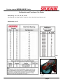
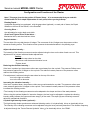
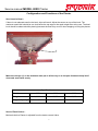
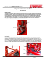
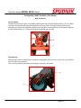
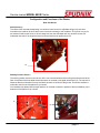
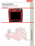
Service manual MODEL 80XX Planter
Field Guide
2007
Planter and CP600 Setup
Part # 290118
page 1 of 173
Service Centers
Phone: (208)785-0480-Fax: (208)785-1497
E-Mail: [email protected]
Web Site : www.spudnik.com
BLACKFOOT
584 West 100 North
P.O. Box 1045
Blackfoot, ID 83221
Phone (208)785-0480
Fax (208)785-1497
PASCO
GRAFTON
5802 North Industrial Way
Pasco, Wa. 99301
Phone (509) 543-7166
Fax (509) 543-7169
1410 12th St. West
Grafton, Nd. 58237
Phone (701) 352-9603
Fax (701) 352-9610
HEYBURN
PRESQUE ISLE
300 Centennial Dr.
Heyburn, ID 83336
Phone (208)436-8052
Fax (208) 436-9170
110 Airport Dr.
Presque Isle, Me. 04769
Phone (207) 764-4686
Fax (207) 764-4674
Service manual MODEL 80XX Planter
Configuration and functions of the machine
Method of operation of the machine
The SPUDNIK planter is designed for planting potatoes.
This describes the configurations and functions
page 3
Service manual MODEL 80XX Planter
Special safety instructions
Safety devices
Never stand beneath suspended loads!
Never stand or work beneath suspended loads!
Engage safety catches!
Never stand or work beneath suspended loads.
Adjustment and maintenance work on parts of the machine may only be carried out
with the safety devices engaged.
page 4
Service manual MODEL 80XX Planter
Configuration and Functions of the Planter
Row Spacing – 32”, 34”, 36”, 38”, 36-40”
Move planting unit, hopper, top bin, extension, shoes, also the first and last row unit.
Seed Spacing – 6-18”
Rear
Front
page 5
Service manual MODEL 80XX Planter
Configuration and Functions of the Planter
Note ! This page gives the key points of Planter Setup… It is recommended that you read this
Guide further for an in-depth explanation of each point, before you begin Setup.
Planting Depth –
Is adjusted depending how equipped, with the gage wheel (optional) on each pair of shoes, the Depth
Wheels on the front of the Planter, or the Draw Bar
Covering Discs –
Are adjustable for angle, depth, and width.
Check and Tighten Drive Chain Idlers –
Mechanical drive, and chemical box drives.
Cup belt shaker –
The rear side of the cup belt has two V-ledges. The movement of the V-ledges over the pressure rollers
causes a vibrating motion. This vibration motion prevents dual seed allocations in the planting cups.
Adjust vibration intensity –
The intensity of the vibration movement can be adjusted using the lever on the side of each row unit. This
adjustment is for intense individual shaker adjustments.
Setting:
-Loosens the star wheel on the side.
-Move lever until the desired vibration is met.
-Tighten wheel.
Reducing the vibration intensity –
If the lever is pushed up, the pressure rollers are moved away from the cup belt. The pressure Rollers exert
less pressure against the V-ledges on the cup belt. The reduced contact pressure of the pressure rollers
reduces the vibrating motion.
Fine adjustment is achieved using the star wheel on the top of the lever.
-turn to the right to increase
-turn to the left to decrease
Increasing the vibration intensity –
If the lever is pushed down, the pressure rollers are moved towards the cup belt. The pressure rollers exert
more pressure against the V-ledges on the cup belt. The increased contact pressure of the pressure rollers
increases the vibrating motion.
*The intensity of the vibrating movement must be adapted to the shape and size of the seed potatoes.
*When using the optional Hydraulic intensive vibrators, the level may be adjusted to regulate the vibrating
intensity solely between the upper and lower step (E) of the crank. The steps (M) are exclusively meant to
adjust the mechanical vibrations.
Cup belt high-intensity shaker (optional) –
The high-intensity shaker produces an enhanced vibrating motion. It is hydraulically driven or electrically driven.
The intensity of the vibrating movement can be adjusted using the lever previously described. The vibration frequency
is adjusted through the Tractor Remote Hydraulic Valve, or for electrically driven, the CP600.
6
Service manual MODEL 80XX Planter
Configuration and Functions of the Planter
Seed Level in Bowl –
If there is not adequate seed in the bowl, skips will result. Adjust the sensor on top of the bowl. The
maximum seed level should be one inch below the top edge to the seed weight door at the rear. The bowl
level should be observed while planting because the bowl may over fill when stopping or lifting the planter.
1
Make sure the pin (1) on the stainless steel pan is all the way in so the pan vibrates to keep itself
clean and seed feeds evenly.
Specifications
Model
Weight:
Hopper Capacity:
8040
8060
8080
9,000 lb.
13,500
18,000
7,000 to 8,000 lb.
11,000 to 12,000 lb.
15,000 to 16,000 lb.
Seed of Feed Chains –
Mechanical drive Planter is adjusted from the tractor remote Valve.
7
Service manual MODEL 80XX Planter
Configuration and Functions of the Planter
Row Unit Set-Up
To achieve the highest accuracy while planting it is important to have the row unit properly adjusted.
Feed Chain Speed –
The speed of the feed chains can be set by adjusting the flow control Needle valve (1) in the front center of the
planter. On a mechanical drive planter it can be adjusted with the flow control on the tractor valve. This speed
should not be too fast to throw potatoes at the belt. However it must be fast enough to keep the seed bin full.
Seed Bin Level –
Before adjusting the row unit itself it is important to set the level of the seed bin. There are two ways to do this:
1. Loosen the carriage bolt (2) on the sensor bracket and slide the sensor to the desired position.
2. With a small screwdriver tighten or loosen the adjusting screw (3) located on the sensor itself. This changes.
The “seeing” distance of the sensor. This screw is located on top of the sensors with plastic connectors and on
the side of the barrel of the sensors with the metal connectors.
1
2
3
The level of the seed bin is critical. There must be enough seed in the bin so that there are no skips as the cups
come out of the potatoes. If this level is too high it is difficult to shake off all of the doubles.
Note: This bin level greatly effects how the shakers and the belt react. If you change this level you will
have to adjust the shakers.
Shaker Frequency –
The electrical and hydraulic shaker options offer a high frequency vibration to the belt and cups. This frequency
is adjustable from ~0 to 2100 Hz. A good starting point is about 50-60% of the maximum shake. This is adjusted
on hydraulic shakers in one of two ways , with the CP 600 Control Box using the control panel. Without the CP
600 Control Box , using the Tractor’s Remote. On electric shakers with CP600 it is adjusted by pressing the
button under the bar graph entitled “shaker” and then adjusting the value with the knob. If the button stays on it
will be in a manual override mode and not shut off the shakers at the end of the field. When you are done
adjusting the shaker make sure to press the button again so that the light goes off.
page 8
Service manual MODEL 80XX Planter
Configuration and Functions of the Planter
Row Unit Set-Up
Shaker Position –
The position of the shaker is the most effective adjustment when trying to change the shake for different seed
and different conditions. There is a coarse adjustment knob (4) and a fine adjustment knob (5). A good starting
point is to loosen the coarse adjustment and with the shaker on let it move to a stabilized point. Tighten the
course adjustment and with the shaker on let it move to a stabilized point. Tighten the course adjustment and
them move the shaker in (more shake) or out (less shake) depending on seed cut and the planting speed.
Turning the fin adjustment knob (5) clockwise will add more shake.
4
5
Seed Depth –
The seed depth is controlled by controlling the depth of the front of the planter. On a planter with front depth
wheels this is done by adjusting the turnbuckles (6) on the depth wheels. On a drawbar style planter ( with no
depth wheels ) the depth is controlled with the drawbar cylinder (7) on the drawbar, (8) and Cylinder Stops ( 3/4”
to 2” in ¼” increments ) placed around the shaft (9) to achieve proper depth. There is also a small gage wheel
attachment available that controls two rows independent of the others. This is a mechanical linkage adjustment.
6
7
8
9
page 9
Service manual MODEL 80XX Planter
Configuration and Functions of the Planter
Row Unit Set-Up
Covering Disks –
The down pressure on the discs is controlled by tightening the spring with the adjustment knob (10). For a wider
Hill remove the bolts and slide each disc assembly out from the center. The angel of the discs can also be
changed by moving the disc assembly to another hole combination. A fine adjustment can be made by adjusting
the rear adjustment bolt (11). Tighten all bolts after final adjustments are made.
10
11
Seed Spacing –
Seed spacing is set on a mechanical drive planter by changing the ratio of the front (12) and rear (13) sprockets
on the front drive of the planters.
This is set on a hydraulic drive planter by changing the spacing in the CP600.
13
12
page 10
Service manual MODEL 80XX Planter
Configuration and Functions of the Planter
Row Unit Set-Up
Seed Accuracy –
To achieve more accurate seed spacing it is critical to control seed roll. Adjustable wings (14) have been
mounted on the inside of the shoe which move in and out according to soil conditions. The goal is to try to pin
the seed as it falls into the furrow. If the soil wraps too soon the seed depth will vary as there is loose soil
underneath the seed. If the wings are back too far the seed has an opportunity to roll.
14
Working Position Sensor –
The working position sensor is used to turn off the row units and shakers while turning around at the end of the
field. On a planter with front depth wheels this sensor is mounted on the depth wheel itself (15). The top hole is
slotted so that the turnbuckle moves up and down as there tire is lifted off the ground. The sensor senses the
turnbuckle end to know if the planter is up or down.
On a drawbar style planter without depth wheels it is mounted to sense the position of the front drawbar (16) to
determine of the planter is up or down.
15
16
page 11
Service manual MODEL 80XX Planter
Parts Breakdown
The following diagram shows how the CP600 Control Box is connected to the MDA
Processor.
4
1
2
3
CP600 Control Box
MDA Processor
Item #
Quantity
Part #
Description
1
1
450162
PLATER DISPLAY CP600
2
1
B94.01736
BUS-END PLUG M12x1,8p [x]
3
1
B94.01683
CAN BUS CABLE 80" (2M) M12x1 8-WIRE
or
1
B94.01685
CAN BUS CABLE 196"(5M) M12x1 8-WIRE
or
1
B94.01759
CAN BUS CABLE 315"(8M) M12x1 8-WIRE
4
1
B94.03009
MDA-MAIN ELECTRONIC
CP600 CONTROL BOX
page 12
Service manual MODEL 80XX Planter
CP600 Buttons and Functions
This section will explain the buttons on the CP600 and their functions
3
4
5
Note: The display is not a touch
screen. The dashed arrows indicate
which icon the function buttons
correspond with.
6
1
2
4
Item #
Function
Description of Function
1
On Button
Provides the power to the control box
2
Off Button
Terminates the power to the control box
3
Menu Button
4
Function Buttons
5
Scroll Up
6
Scroll Down
Scrolls down through options of a specific menu
7
Control Dial
Use this for changing settings.
(Note: Some settings may require contacting a
Spudnik technician to be changed)
CP600 CONTROL BOX
7
Allows user to move from the previous menu to the next menu
Use these buttons to choose an icon on the display screen.
These icons, when chosen, will take you to that specific function's settings.
(the function button corresponds with the icon that is directly above/below it)
Scrolls up through options of a specific menu
page 13
Service manual MODEL 80XX Planter
Initial and Default Screens
When power is turned on, this screen will display briefly.
After the previous screen, you will see the default screen:
•When left on any other screen for approximately 8 seconds, the display will default back to this
screen.
•If the skip detection alarm is triggered, this screen will be displayed, unless your are in a deeper
menu at the time of the alarm triggering.
•From this screen, press the menu button to be taken to the main menu.
•Once an alarm is triggered, the buzzer will sound for an adjustable amount of time. If the error is
not resolved, the symbol will remain on the screen, and the buzzer will not sound again. (you may
scroll through the alarm screens by pressing the scroll up button while in the default
screen.)
CP600 CONTROL BOX
page 14
Service manual MODEL 80XX Planter
Moving from Default Screen to Main Menu
Default Screen
While in the Default Screen,
press the Menu Layers button
once to go to the main menu.
Main Menu
Fertilizer Valve
Calibration
Skip Detection
Seed Spacing
Distance
Measurements
Feed Chain
Top Row
Bottom
Row
Service
Row Unit
Hydraulic
Drive
Fertilizer
Hydraulic
Drive
Information
Status/
Diagnostics
Acre Meter
From the Main menu, each screen icon may be chosen by
pressing the function key that is directly above the icon (for
the top row) or below the icon (for the bottom row).
(see: Buttons and Functions)
CP600 CONTROL BOX
page 15
Service manual MODEL 80XX Planter
Skip Detection
(To change this setting, refer to password section or contact a Spudnik Technician)
1)
The reload on cups
should be 94 for red
or green cups and
111 for blue cups
2)
This is the alarm
level which will
trigger an alarm
based on the skip
detection level.
3)
This is the amount
of time the alarm
beep will sound for
4)
This is the
maximum time
frame allowed for
skip detection
before an alarm
sounds.
CP600 CONTROL BOX
page 16
Service manual MODEL 80XX Planter
Feed Chain
After choosing the Feed Chain icon, you will see this display:
If one or more of the seed chains
are OFF, by choosing this icon,
all feed chains will switch to ON.
By pressing the function button directly above
the feed chain icon, you will control whether
that chain is ON or OFF.
Press the scroll down button once
to view the next display
This screen is not used.
Press the scroll down button once
to view the next display
(Continued on the next page)
CP600 CONTROL BOX
page 17
Service manual MODEL 80XX Planter
Feed Chain
(Continued from the previous page)
This portion of the display indicates the chain maximum on time. This displays how many
seconds the chain may run before an alarm will be triggered (Default is 8 seconds). This
alarm being tripped indicates that there could be a bridge problem, where the potatoes are not
able to fall onto the seed chain, or the hopper could be out of seed.
(To change this setting, refer to password section or contact a Spudnik technician.)
Press the scroll down button once
to view the next display
This portion displays the maximum chain pause time. This displays the amount of time the chain may
stay paused before an alarm is triggered, and the buzzer sounds (Default is 80 seconds).
(To change this setting, refer to password section or contact a Spudnik Technician)
Note: If this alarm keeps triggering, the problem may be: 1) Dirty sensor, 2) Shakers are so strong that
they are shaking the seed out of the cup and falling back into the hopper, 3) Driving so slow that the
planter does not have time to plant the seeds that are in the hopper and allow the chain to fill it within 10
seconds (or the current setting), 4)Turning around at the edge of a field may trip the alarm if it takes
longer than 10 seconds (or the current setting).
(Continued on the next page)
CP600 CONTROL BOX
page 18
Service manual MODEL 80XX Planter
Feed Chain
(Continued from the previous page)
This portion displays the amount of time the buzzer will sound for in the event of an alarm. (Default
is 2 seconds).
(To change this setting, refer to password section or contact a Spudnik Technician)
With Feed Chains turned off , an Alarm will sound if the working position of planter is changed (as
in reaching the end of the Row ) by raising the Planter cycling the Working Position sensor
CP600 CONTROL BOX
page 19
Service manual MODEL 80XX Planter
Feed Chain Functions
The Feed Chains may be switched on or off individually. This allows you to leave a path to the center
tower of pivots.
1
4 5 6 7 8
2 3
9
10
Rows may have the feed chain
turned off in order to leave a path to
the center tower of the pivot.
Note: The feed chain is the device that is turned on or off. This means that the belt with the
seed cups will continue to plant seed until the hopper it pulls from is empty. Therefore, the
feed chain must be turned off in time so that the cups will not have seed by the time you
reach your desired destination.
CP600 CONTROL BOX
page 20
Service manual MODEL 80XX Planter
Fertilizer Valve Calibration
To set Fertilizer Valves, follow the steps below:
1)
2)
To set the fertilizer
valves you must make
sure that the fertilizer
valves are turned OFF
and the stop sign
symbol says, ‘STOP’.
The symbol defaults to
‘GO’.
Select the, ‘Fertilizer
Valves’ icon.
Note: use scroll buttons to navigate
through screens
3)
Fertilizer Value
CP600 CONTROL BOX
page 21
Service manual MODEL 80XX Planter
Fertilizer Valve Calibration
4)
Shaft speed for
calibration suggested
# to begin with 2000. If
the shaft speed during
the calibration is too
fast or slow adjust this
value up or down.
5)
The desired rotations
for the calibration.
6)
Desired application
rate
CP600 CONTROL BOX
page 22
Service manual MODEL 80XX Planter
Fertilizer Valve Calibration
7)
Select both A and B
buttons to start
calibration.
A
B
Note: Place bucket under one row unit to measure the weight of the
fertilizer. Then multiply by the number of row units.
i.e. If you have a four row planter and measure the fertilizer weight brought
out through the calibration from one row unit, you need to multiply the weight
by four.
8)
This screen is
calculating the
density
Note: The Density needs to be manually entered from the
weight measurement taken. There is a minimum 2.40 lb and
can not be set lower
CP600 CONTROL BOX
page 23
Service manual MODEL 80XX Planter
Fertilizer Valve Calibration
9)
Select buttons A and B
to calculate and make
sure that the correct
calibration has been
set.
A
10)
B
‘OK’ means that the
calculations are
correct and finished.
11) Calculated Factor
To adjust (fine tune)
press the two
buttons below
Manual. Lowering
the # will reduce the
amount per Acre
CP600 CONTROL BOX
page 24
Service manual MODEL 80XX Planter
Seed Spacing
The seed spacing is measured off of the wheel speed or the radar speed. (optional)
After choosing the seed spacing icon, you will see this display:
Wheel Speed
Radar Speed
This screen displays the
current seed spacing.
This screen displays the
current seed spacing.
(Continued on the next page)
CP600 CONTROL BOX
page 25
Service manual MODEL 80XX Planter
Seed Spacing
(Continued from the previous page)
If the radar speed is not reading correctly, it will need to have an offset
entered. This display allows you to change the offset for the radar.
Note: If the difference in the speed of the wheel and the speed of the radar is greater than
20%, then an alarm will be triggered. In the event of this alarm being triggered, the
machine will automatically switch to measure the seed spacing off of the wheel speed until
the error is resolved.
Press the scroll button once
to view the next display
In case of slippage, different size tires or wheels, etc., the wheel
speed will need to have an offset entered. This display allows you to
change the offset for the tires.
CP600 CONTROL BOX
page 26
Service manual MODEL 80XX Planter
Distance Measurements
The Distance Measurements menu is used for setting up the Chemical boxes and also
measuring the tire circumference.
After choosing the Distance Measurements icon, you will see this display:
This number is the calibration distance. By
turning the dial on the lower right hand corner to
the CP600, you may change this distance.
CP600 CONTROL BOX
page 27
Service manual MODEL 80XX Planter
Hydraulic Drive
To set up the hydraulic drive configuration requires a password and extreme CAUTION. All machines
are set-up at the factory. Make note of factory settings before changing.
Note: Manually running the
hydraulic drive does not
require a password, skip to #3
1)
Select the ‘SERVICE’
icon.
2)
Refer to the password
section to modify the
system parameters.
Use extreme caution
when modifying
parameters! Write
down the existing
parameters before
modifying.
3)
CAUTION:
Select the
‘HYDRAULIC DRIVE’
icon.
CP600 CONTROL BOX
page 28
Service manual MODEL 80XX Planter
Hydraulic Drive
After choosing the Hydraulic Drive icon, you will see this display:
Press two Buttons to empty Bin
This value determines the speed that the row unit seed cups will run
at. This test is often run to empty the bin or clean the cups.
Press the scroll down button
once to view the next display
This value is the slowest speed the cups should run at.
Press the scroll down button
once to view the next display
(Continued on the next page)
CP600 CONTROL BOX
page 29
Service manual MODEL 80XX Planter
Hydraulic Drive
(Continued from the previous page)
This value is the fastest speed the cups should run at.
Press the scroll down button
once to view the next display
The start value is typically about 2000. this is when
the valve is about 20% open.
Press the scroll down button
once to view the next display
(Continued on the next page)
CP600 CONTROL BOX
page 30
Service manual MODEL 80XX Planter
Hydraulic Drive
(Continued from the previous page)
The proportional value is 40-50. On 2006 machines
they will be factory set to 50.
Press the scroll down button
once to view the next display
The integration factor value for all machines is 20.
CP600 CONTROL BOX
page 31
Service manual MODEL 80XX Planter
Fertilizer Hydraulic Drive
To set up the hydraulic drive configuration requires a password and extreme CAUTION. All machines
are set-up at the factory. Make note of factory settings before changing.
Note: Manually running the
hydraulic drive does not
require a password, skip to #3
1)
Select the ‘SERVICE’
icon.
2)
Refer to the password
section to modify the
system parameters.
Use extreme caution
when modifying
parameters! Write
down the existing
parameters before
modifying.
3)
CAUTION:
Select the
‘FERTILIZER
HYDRAULIC DRIVE’
icon.
CP600 CONTROL BOX
page 32
Service manual MODEL 80XX Planter
Fertilizer Hydraulic Drive
After choosing the Fertilizer Hydraulic Drive icon, you will see this display:
This value determines the speed that the fertilizer box valves will run
at. This test is often run to empty the bin or clean the cups.
Press the scroll down button
once to view the next display
This value is the slowest speed the valves should run at.
Press the scroll down button
once to view the next display
(Continued on the next page)
CP600 CONTROL BOX
page 33
Service manual MODEL 80XX Planter
Fertilizer Hydraulic Drive
(Continued from the previous page)
Two buttons
for test mode
This value is the fastest speed the valves should run at.
Press the scroll down button
once to view the next display
The start value is typically about 2000. this is when
the valve is about 20% open.
Press the scroll down button
once to view the next display
(Continued on the next page)
CP600 CONTROL BOX
page 34
Service manual MODEL 80XX Planter
Fertilizer Hydraulic Drive
(Continued from the previous page)
The proportional value is 40-50. On 2006 machines
they will be factory set to 50.
Press the scroll down button
once to view the next display
The integration factor value for all machines is 20.
CP600 CONTROL BOX
page 35
Service manual MODEL 80XX Planter
Acre Meter
After choosing the acre meter icon, you will see this display:
Press the function buttons above
the resets to reset the value.
Acres are measured
in 10 acre intervals.
This section displays how many
acres have been planted.
This section displays the
number of seed per acre being
planted.
Press the scroll down button
once to view the next display
This section displays the
current row spacing.
Press the scroll down button
once to view the next display
(Continued on the next page)
CP600 CONTROL BOX
page 36
Service manual MODEL 80XX Planter
Acre Meter
(Continued from the previous page)
This is the circumference of the tire that the sensor is
on. The sensor could be placed on either the front or
the rear wheel of the machine.
Factory Circumference Settings
Tire Nomenclatures
Circumference
Front Tire 11.25x24
Rear Tire 11.5x24
Rear Tire 12.5x16
Rear Tire 14.9x24
Note: The tire circumference listed above is figured only theoretically. The practical
measurement must be determined by the customer (operator). This can be done by,
1. Loading the hopper only half full
2. Place a mark or a marker on the tire with the sensor.
3. Plant ten revolutions of the tire.
4. Measure start to stop distance.
5. Dividing the distance by ten will give an accurate circumference value for the CP600
CP600 CONTROL BOX
page 37
Service manual MODEL 80XX Planter
Information
After choosing the information icon, you will see this screen displayed:
This section displays the errors
that have occurred.
CP600 CONTROL BOX
This section displays the
software versions in the MDA
box, and also the CP600
page 38
Service manual MODEL 80XX Planter
Status/ Diagnostics
The Status/ Diagnostics section allows you to monitor specific sections of the machine.
The following describes each icon’s meaning:
This icon indicates an okay, open circuit status.
This icon indicates an okay, closed circuit status.
This icon indicates a short circuit to ground.
This icon indicates a broken wire.
CP600 CONTROL BOX
page 39
Service manual MODEL 80XX Planter
Status/ Diagnostics
After choosing the Status/ Diagnostics icon, you will see this display:
The following screens display the status of the described area of the machine.
This section displays the sip detection status.
Press the scroll down button
once to view the next display
This section displays the feed chain status.
Press the scroll down button
once to view the next display
(Continued on the next page)
CP600 CONTROL BOX
page 40
Service manual MODEL 80XX Planter
Status/ Diagnostics
(Continued from the previous page)
This section displays the feed chain status.
Press the scroll down button
once to view the next display
This section displays the fertilizer valve status.
Press the scroll down button
once to view the next display
(Continued on the next page)
CP600 CONTROL BOX
page 41
Service manual MODEL 80XX Planter
Status/ Diagnostics
(Continued from the previous page)
This section displays the dry fertilizer box encoder status of
the clutch.
Press the scroll down button
once to view the next display
This section displays the chemical box clutch status.
Press the scroll down button
once to view the next display
(Continued on the next page)
CP600 CONTROL BOX
page 42
Service manual MODEL 80XX Planter
Status/ Diagnostics
(Continued from the previous page)
This section displays the hydraulic motor status.
Press the scroll down button
once to view the next display
This section displays the impulses from the belt, wheel,
the radar, and the working position sensor status.
Press the scroll down button
once to view the next display
(Continued on the next page)
CP600 CONTROL BOX
page 43
Service manual MODEL 80XX Planter
Status/ Diagnostics
(Continued from the previous page)
Press the scroll down button
once to view the next display
Press the scroll down button
once to view the next display
(Continued on the next page)
CP600 CONTROL BOX
page 44
Service manual MODEL 80XX Planter
Status/ Diagnostics
(Continued from the previous page)
Press the scroll down button
once to view the next display
CP600 CONTROL BOX
page 45
Service manual MODEL 80XX Planter
Storage
The CP600 should be stored in a dry storage place away from moisture and damp areas.
Keep the CP600 away from areas with excessive dust.
Password
The password for changing parameters in the CP600 is 11
Note: To get back out of password mode restart CP600 by turning OFF
and back on again.
CP600 CONTROL BOX
page 46
Service manual MODEL 80XX Planter
Parameter Settings
Use the open boxes below to make NOTE of the default parameter settings before changing.
Service Adjustments
Spudnik
Adjustments
Factory Specs.
Name & Date
Service 1
Name & Date
Service 2
Name & Date
Tire
Circumference
Row Spacing
Hydraulic Row Unit Drive
I min
I max
I start
Xp
Xi
Reload
CP600 CONTROL BOX
page 47
Service manual MODEL 80XX Planter
Parameter Settings
Use the open boxes below to make NOTE of the default parameter settings before changing.
Service Adjustments
Spudnik
Adjustments
Factory Specs.
Name & Date
Service 1
Name & Date
Service 2
Name & Date
Hydraulic Fertilizer Drive
I min
I max
I start
Xp
Xi
CP600 CONTROL BOX
page 48
Service manual MODEL 80XX Planter
Notes!
page 49