1
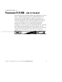
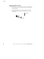
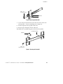
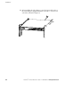
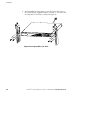
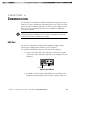
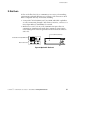
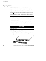
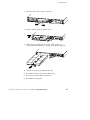
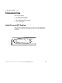
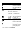
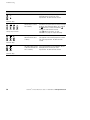
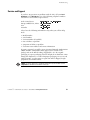
® Powerware 5115 RM User’s Guide 500–1500 VA www.powerware.com US Patent 6,462,961 Class B EMC Statements FCC Part 15 NOTE This equipment has been tested and found to comply with the limits for a Class B digital device, pursuant to part 15 of the FCC Rules. These limits are designed to provide reasonable protection against harmful interference in a residential installation. This equipment generates, uses and can radiate radio frequency energy and, if not installed and used in accordance with the instructions, may cause harmful interference to radio communications. However, there is no guarantee that interference will not occur in a particular installation. If this equipment does cause harmful interference to radio or television reception, which can be determined by turning the equipment off and on, the user is encouraged to try to correct the interference by one or more of the following measures: : Reorient or relocate the receiving antenna. : Increase the separation between the equipment and the receiver. : Connect the equipment into an outlet on a circuit different from that to which the receiver is connected. : Consult the dealer or an experienced radio/TV technician for help. ICES-003 This Class B Interference Causing Equipment meets all requirements of the Canadian Interference Causing Equipment Regulations ICES-003. Cet appareil numérique de la classe B respecte toutes les exigences du Reglement sur le matériel brouilleur du Canada. Requesting a Declaration of Conformity Units that are labeled with a CE mark comply with the following harmonized standards and EU directives: : Harmonized Standards: EN 50091-1-1 and EN 50091-2; IEC 950 Second Edition, Amendments A1, A2, A3, and A4 : EU Directives: 73/23/EEC, Council Directive on equipment designed for use within certain voltage limits 93/68/EEC, Amending Directive 73/23/EEC 89/336/EEC, Council Directive relating to electromagnetic compatibility 92/31/EEC, Amending Directive 89/336/EEC relating to EMC The EC Declaration of Conformity is available upon request for products with a CE mark. For copies of the EC Declaration of Conformity, contact: Powerware Corporation Koskelontie 13 FIN-02920 Espoo Finland Phone: +358-9-452 661 Fax: +358-9-452 665 68 Powerware and ABM are registered trademarks and X-Slot and ConnectUPS are trademarks of Powerware Corporation. .Copyright 2002-2003 Powerware Corporation, Raleigh, NC, USA. All rights reserved. No part of this document may be reproduced in any way without the express written approval of Powerware Corporation. Special Symbols The following are examples of symbols used on the UPS to alert you to important information: CAUTION Risk of Electric Shock Do Not Open Cover CAUTION To reduce the risk of electric shock, Do not remove cover (or back) No user-serviceable parts inside Refer servicing to the factory RISK OF ELECTRIC SHOCK - Indicates that a risk of electric shock is present and the associated warning should be observed. CAUTION: REFER TO OPERATOR’S MANUAL - Refer to your operator’s manual for additional information, such as important operating and maintenance instructions. SAFETY EARTHING TERMINAL - Indicates the primary safety ground. LOAD ON/OFF - Press the button with this symbol to energize the output receptacles ( indicator illuminates) or to de-energize the output receptacles indicator is off). ( RJ-45 RECEPTACLE - For 230V models only: this receptacle provides network interface connections. Do not plug telephone or telecommunications equipment into this receptacle. This symbol indicates that you should not discard the UPS or the UPS batteries in the trash. The UPS may contain sealed, lead-acid batteries. Batteries must be recycled. TABLE OF CONTENTS 1 Powerware 5115 RM – One of the Best! . . . . . . . . . . . . . . . . . . . . . . . . . . . . . . 1 2 Safety Warnings . . . . . . . . . . . . . . . . . . . . . . . . . . . . . . . . . . . . . . . . . . . . . . . . . 3 3 Installation . . . . . . . . . . . . . . . . . . . . . . . . . . . . . . . . . . . . . . . . . . . . . . . . . . . . . 19 Inspecting the Equipment . . . . . . . . . . . . . . . . . . . . . . . . . . . . . . . . . . . . . . . . . . . . . . . . . . . . . . . . UPS Setup . . . . . . . . . . . . . . . . . . . . . . . . . . . . . . . . . . . . . . . . . . . . . . . . . . . . . . . . . . . . . . . . . . Mounting the UPS in a 19” Rack . . . . . . . . . . . . . . . . . . . . . . . . . . . . . . . . . . . . . . . . . . . . . . . . Mounting the UPS in a 23” Rack . . . . . . . . . . . . . . . . . . . . . . . . . . . . . . . . . . . . . . . . . . . . . . . . Zero-U Mounting . . . . . . . . . . . . . . . . . . . . . . . . . . . . . . . . . . . . . . . . . . . . . . . . . . . . . . . . . . . Wall-Mount Setup . . . . . . . . . . . . . . . . . . . . . . . . . . . . . . . . . . . . . . . . . . . . . . . . . . . . . . . . . . Installing the UPS . . . . . . . . . . . . . . . . . . . . . . . . . . . . . . . . . . . . . . . . . . . . . . . . . . . . . . . . . . . . . 19 19 20 23 25 26 27 4 Operation . . . . . . . . . . . . . . . . . . . . . . . . . . . . . . . . . . . . . . . . . . . . . . . . . . . . . . 29 Turning the UPS On . . . . . . . . . . . . . . . . . . . . . . . . . . . . . . . . . . . . . . . . . . . . . . . . . . . . . . . . . . . . Starting the UPS on Battery . . . . . . . . . . . . . . . . . . . . . . . . . . . . . . . . . . . . . . . . . . . . . . . . . . . . Turning the UPS Off . . . . . . . . . . . . . . . . . . . . . . . . . . . . . . . . . . . . . . . . . . . . . . . . . . . . . . . . . . . Standby Mode . . . . . . . . . . . . . . . . . . . . . . . . . . . . . . . . . . . . . . . . . . . . . . . . . . . . . . . . . . . . . . . UPS Front Panel . . . . . . . . . . . . . . . . . . . . . . . . . . . . . . . . . . . . . . . . . . . . . . . . . . . . . . . . . . . . . . Initiating the Self-Test . . . . . . . . . . . . . . . . . . . . . . . . . . . . . . . . . . . . . . . . . . . . . . . . . . . . . . . . . . 29 29 29 30 30 30 5 Additional UPS Features . . . . . . . . . . . . . . . . . . . . . . . . . . . . . . . . . . . . . . . . . . 31 Voltage Configuration . . . . . . . . . . . . . . . . . . . . . . . . . . . . . . . . . . . . . . . . . . . . . . . . . . . . . . . . . . 31 Network Transient Protector . . . . . . . . . . . . . . . . . . . . . . . . . . . . . . . . . . . . . . . . . . . . . . . . . . . . . 32 Load Segments . . . . . . . . . . . . . . . . . . . . . . . . . . . . . . . . . . . . . . . . . . . . . . . . . . . . . . . . . . . . . . . 33 6 Communication . . . . . . . . . . . . . . . . . . . . . . . . . . . . . . . . . . . . . . . . . . . . . . . . . 35 USB Port . . . . . . . . . . . . . . . . . . . . . . . . . . . . . . . . . . . . . . . . . . . . . . . . . . . . . . . . . . . . . . . . . . . 35 Communication Port . . . . . . . . . . . . . . . . . . . . . . . . . . . . . . . . . . . . . . . . . . . . . . . . . . . . . . . . . . . 36 X-Slot Cards . . . . . . . . . . . . . . . . . . . . . . . . . . . . . . . . . . . . . . . . . . . . . . . . . . . . . . . . . . . . . . . . . 37 7 UPS Maintenance . . . . . . . . . . . . . . . . . . . . . . . . . . . . . . . . . . . . . . . . . . . . . . . 39 UPS and Battery Care . . . . . . . . . . . . . . . . . . . . . . . . . . . . . . . . . . . . . . . . . . . . . . . . . . . . . . . . . . 39 Storing the UPS and Batteries . . . . . . . . . . . . . . . . . . . . . . . . . . . . . . . . . . . . . . . . . . . . . . . . . . 39 Replacing Batteries . . . . . . . . . . . . . . . . . . . . . . . . . . . . . . . . . . . . . . . . . . . . . . . . . . . . . . . . . . . . 40 Powerware® 5115 Rack-Mount User’s Guide : 164201449 Rev A www.powerware.com i Table of Contents Testing New Batteries . . . . . . . . . . . . . . . . . . . . . . . . . . . . . . . . . . . . . . . . . . . . . . . . . . . . . . . . . . 42 Recycling the Used Battery . . . . . . . . . . . . . . . . . . . . . . . . . . . . . . . . . . . . . . . . . . . . . . . . . . . . . . 42 8 Specifications . . . . . . . . . . . . . . . . . . . . . . . . . . . . . . . . . . . . . . . . . . . . . . . . . . 43 9 Troubleshooting . . . . . . . . . . . . . . . . . . . . . . . . . . . . . . . . . . . . . . . . . . . . . . . . . 47 Audible Alarms and UPS Conditions . . . . . . . . . . . . . . . . . . . . . . . . . . . . . . . . . . . . . . . . . . . . . . . . Silencing an Audible Alarm . . . . . . . . . . . . . . . . . . . . . . . . . . . . . . . . . . . . . . . . . . . . . . . . . . . . Site Wiring Fault (120V Models Only) . . . . . . . . . . . . . . . . . . . . . . . . . . . . . . . . . . . . . . . . . . . . . Service and Support . . . . . . . . . . . . . . . . . . . . . . . . . . . . . . . . . . . . . . . . . . . . . . . . . . . . . . . . . . . ii 47 48 48 51 Powerware® 5115 Rack-Mount User’s Guide : 164201449 Rev A www.powerware.com CHAPTER 1 POWERWARE 5115 RM – ONE OF THE BEST! The Powerware9 5115 Rack-Mount (RM) uninterruptible power system (UPS) is a high-density power protection solution ideal for servers, storage systems, network equipment, and other critical devices. The slim design and wide range of installation possibilities make the Powerware 5115 RM the most versatile UPS available. With only 1U (1.75”) of rack-height, the UPS can be installed in rack-mount, wall-mount, side-mount (zero U), and bench-top applications. Providing a true sine wave output, the UPS delivers smooth, continuous power during normal and battery operation. In addition, the UPS corrects incoming voltage fluctuations to further protect the connected equipment from power problems such as power sags and surges. Powerware® 5115 Rack-Mount User’s Guide : 164201449 Rev A www.powerware.com 1 Powerware 5115 RM – ONE OF THE BEST! : Network Transient Protector guards your network communications equipment from surges. Low voltage models can also protect modems, fax machines, or other telecommunications equipment. : Optional X-SlotZ modules provide enhanced communication capabilities for increased power protection and control. : The Powerware 5115 RM is backed by worldwide agency approvals. 2 Powerware® 5115 Rack-Mount User’s Guide : 164201449 Rev A www.powerware.com CHAPTER 2 SAFETY WARNINGS Read the following precautions before you install the UPS. IMPORTANT SAFETY INSTRUCTIONS SAVE THESE INSTRUCTIONS This manual contains important instructions that you should follow during installation and maintenance of the UPS and batteries. Please read all instructions before operating the equipment and save this manual for future reference. DANGER This UPS contains LETHAL VOLTAGES. All repairs and service should be performed by AUTHORIZED SERVICE PERSONNEL ONLY. There are NO USER SERVICEABLE PARTS inside the UPS. WARNING : This UPS contains its own energy source (batteries). The output receptacles may carry live voltage even when the UPS is not connected to an AC supply. : For 200–240V models, the output receptacles may remain electrically live. If the input power source in your application is wired line-to-neutral (as in most European applications), the voltage to the output receptacles is 0V. With line-to-line input wiring, the voltage to the output receptacles is 100–120V (measured from line-to-ground or line-to-neutral, depending on the UPS wiring). : Do not remove or unplug the input cord when the UPS is turned on. This removes the safety ground from the UPS and the equipment connected to the UPS. : To reduce the risk of fire or electric shock, install this UPS in a temperature and humidity controlled, indoor environment, free of conductive contaminants. Ambient temperature must not exceed 40C (104F). Do not operate near water or excessive humidity (95% max). : To comply with international standards and wiring regulations, the total equipment connected to the output of this UPS must not have an earth leakage current greater than 3.5 milliamperes. Powerware® 5115 Rack-Mount User’s Guide : 164201449 Rev A www.powerware.com 3 Safety Warnings CAUTION : The wall outlet must be within 2 meters of the equipment and accessible to the operator. : Batteries can present a risk of electrical shock or burn from high short-circuit current. The following precautions should be observed: 1) Remove watches, rings, or other metal objects; 2) Use tools with insulated handles; 3) Do not lay tools or metal parts on top of batteries; 4) Disconnect charging source prior to connecting or disconnecting battery terminals. : Proper disposal of batteries is required. Refer to your local codes for disposal requirements. : Never dispose of batteries in a fire. Batteries may explode when exposed to flame. : Never open or mutilate batteries. Released electrolyte is harmful to the skin and eyes, and may be extremely toxic. : Replace batteries with the same number and type of batteries as originally installed in the UPS. Sikkerhedsanvisninger VIGTIGE SIKKERHEDSANVISNINGER GEM DISSE ANVISNINGER DENNE BRUGERVEJLEDNING INDEHOLDER VIGTIGE SIKKERHEDSANVISNINGER FARE Denne UPS indeholder LIVSFARLIG HØJSPÆNDING. Alle reparationer og vedligeholdelse bør kun udføres af en AUTORISERET SERVICETEKNIKER. Ingen af UPS’ens indvendige dele kan repareres af brugeren. ADVARSEL! : Denne UPS indeholder egen energiforsyning (batterier). Udgangsnetstikkene kan lede strøm, selv når UPS’en ikke er tilsat en AC-energikilde. : Netledningen må ikke fjernes og stikket må ikke trækkes ud, mens UPS’en er tændt. Dette fjerner sikkerhedsjorden fra UPS’en og fra det udstyr, der er sat til. : Installér denne UPS i et temperatur- og fugtighedskontrolleret indendørsmiljø, frit for ledende forureningsstoffer for at formindske risikoen for brand og elektrisk stød. Rumtemperaturen må ikke overstige 40C. UPS’en bør ikke betjenes nær vand eller høj fugtighed (maksimalt 95%). 4 Powerware® 5115 Rack-Mount User’s Guide : 164201449 Rev A www.powerware.com Safety Warnings : I overensstemmelse med internationale normer og bestemmelser for el-installation må det udstyr, der er forbundet til udgangen af denne UPS, tilsammen ikke overskride en jordafdelingsspænding på mere end 3,5 milliampere. ADVARSEL : Stikkontakten skal være højest 2 meter fra udstyret og skal være tilgængeligt til operatøren. : Batterier kan udgøre en fare for elektrisk stød eller forbrændinger forårsaget af høj kortslutningsspænding. De korrekte forholdsregler bør overholdes. : Korrekt bortskaffelse af batterier er påkrævet. Overhold gældende lokale regler for bortskaffelsesprocedurer. : Skaf dig aldrig af med batterierne ved at brænde dem. Batterierne kan eksplodere ved åben ild. : Batterierne bør aldrig åbnes eller skilles ad. Udløst elektrolyt er skadeligt for hud og øjne og kan være yderst giftigt. Belangrijke Veiligheidsinstructies BELANGRIJKE VEILIGHEIDSINSTRUCTIES BEWAAR DEZE INSTRUCTIES DEZE HANDLEIDING BEVAT BELANGRIJKE VEILIGHEIDSINSTRUCTIES GEVAAR Deze UPS bevat LEVENSGEVAARLIJKE ELEKTRISCHE SPANNING. Alle reparaties en onderhoud dienen UITSLUITEND DOOR ERKEND SERVICEPERSONEEL te worden uitgevoerd. Er bevinden zich GEEN ONDERDELEN in de UPS die DOOR DE GEBRUIKER kunnen worden GEREPAREERD. WAARSCHUWING : Deze UPS bevat zijn eigen energiebron (batterijen). De uitgangsaansluitingen kunnen onder spanning staan wanneer de UPS niet op een wisselstroom voeding is aangesloten. : Verwijder de ingangsnoer niet of haal de stekker van de ingangsnoer er niet uit terwijl de UPS aan staat. Hierdoor zou de UPS en uw aangesloten apparatuur geen aardebeveiliging meer hebben. Powerware® 5115 Rack-Mount User’s Guide : 164201449 Rev A www.powerware.com 5 Safety Warnings : Teneinde de kans op brand of elektrische schok te verminderen dient deze UPS in een gebouw met temperatuur- en vochtigheidregeling te worden geïnstalleerd, waar geen geleidende verontreinigingen aanwezig zijn. De omgevingstemperatuur mag 40C niet overschrijden. Niet gebruiken in de buurt van water of bij zeer hoge vochtigheid (max. 95%). : Om aan de internationale normen en bedradingsvoorschriften te voldoen mag de gehele apparatuur die op de uitgang van deze UPS is aangesloten, geen aardlekstroom van meer dan 3,5 milliampère hebben. OPGELET : De hoofdvoedingcontactdoos moet zich op minder dan 2 meter vande apparatuur bevinden en makkelijk bereikbaar zijn voor de gebruiker. : Batterijen kunnen gevaar voor elektrische schok of brandwonden veroorzaken als gevolg van un hoge kortsluitstroom. Volg de desbetreffende aanwijzingen op. : De batterijen moeten op de juiste wijze worden opgeruimd. Raadpleeg hiervoor uw plaatselijke voorschriften. : Nooit batterijen in het vuur gooien. De batterijen kunnen ontploffen. : Nooit batterijen openen of verminken. Vrijkomend elektrolyt is schadelijk voor de huid en ogen, en kan uiterst giftig zijn. Tarkeita Turvaohjeita TÄRKEITÄ TURVAOHJEITA - SUOMI SÄILYTÄ NÄMÄ OHJEET TÄMÄ OPAS SISÄLTÄÄ TÄRKEITÄ TURVAOHJEITA VAARA Tämä UPS sisältää HENGENVAARALLISIA JÄNNITTEITÄ. Kaikki korjaukset ja huollot on jätettävä VAIN VALTUUTETUN HUOLTOHENKILÖN TOIMEKSI. UPS ei sisällä MITÄÄN KÄYTTÄJÄN HUOLLETTAVIA OSIA. VAROITUS : Tämä UPS sisältää oman energialähteen (akuston). Ulostuloliittimissä voi olla jännite, kun UPS ei ole liitettynä verkkojännitteeseen. : Älä poista tai irrota sisääntulojohtoa, kun UPS on kytkettynä. Tämä poistaa turvamaadoituksen UPS-laitteesta ja siihen liitetystä laitteistosta. 6 Powerware® 5115 Rack-Mount User’s Guide : 164201449 Rev A www.powerware.com Safety Warnings : Vähentääksesi tulipalon ja sähköiskun vaaraa asenna tämä UPS sisätiloihin, joissa lämpötila ja kosteus on säädettävissä ja joissa ei ole virtaa johtavia epäpuhtauksia. Ympäristön lämpötila ei saa ylittää 40 C. Älä käytä lähellä vettä ja vältä kosteita tiloja (95 % maksimi). : Kansainväliset normit ja johdotusmääräykset vaativat, että kaikkien tämän UPS-laitteen ulostulokytkentöjen yhteinen maavuotovirta ei ylitä 3,5 milliampeeria (mA). VARO : Päävirtapistokkeen täytyy olla 2 m:n säteellä laitteistosta ja käyttäjän saatavilla. UPS-laitteen virtakytkin ei eristä sisäosia virran saannilta. : Akusto saattaa aiheuttaa sähköiskun tai syttyä tuleen, jos akusto kytketään oikosulkuun. Noudata asianmukaisia ohjeita. : Akusto täytyy hävittää säädösten mukaisella tavalla. Noudata paikallisia määräyksiä. : Älä koskaan heitä akkuja tuleen. Ne voivat räjähtää. : Älä avaa tai riko akkua. Paljastunut elektrolyytti on vahingollinen iholle ja silmille ja voi olla erittäin myrkyllistä. Consignes de sécurité CONSIGNES DE SÉCURITÉ IMPORTANTES CONSERVER CES INSTRUCTIONS CE MANUEL CONTIENT DES CONSIGNES DE SÉCURITÉ IMPORTANTES DANGER! Cet onduleur contient des TENSIONS MORTELLES. Toute opération d’entretien et de réparation doit être EXCLUSIVEMENT CONFIÉE A UN PERSONNEL QUALIFIÉ AGRÉÉ. AUCUNE PIÈCE RÉPARABLE PAR L’UTILISATEUR ne se trouve dans l’onduleur. AVERTISSEMENT! : Cet onduleur renferme sa propre source d’énergie (batteries). Les prises de sortie peuvent être sous tension même lorsque l’onduleur n’est pas branché sur le secteur. : Ne pas retirer le cordon d’alimentation lorsque l’onduleur est sous tension sous peine de supprimer la mise à la terre de l’onduleur et du matériel connecté. Powerware® 5115 Rack-Mount User’s Guide : 164201449 Rev A www.powerware.com 7 Safety Warnings : Pour réduire les risques d’incendie et de décharge électrique, installer l’onduleur uniquement à l’intérieur, dans un lieu dépourvu de matériaux conducteurs, où la température et l’humidité ambiantes sont contrôlées. La température ambiante ne doit pas dépasser 40 C. Ne pas utiliser à proximité d’eau ou dans une atmosphère excessivement humide (95 % maximum). : Afin d’être conforme aux normes et règlements internationaux de câblage, le courant de fuite à la terre de la totalité du matériel branché sur la sortie de l’onduleur ne doit pas dépasser 3,5 mA. ATTENTION! : La prise principale secteur doit se trouver à moins de 2 mètres du matériel et être accessible à l’utilisateur. : Les batteries peuvent présenter un risque de décharge électrique ou de brûlure par des courts-circuits de haute intensité. Prendre les précautions nécessaires. : Une mise au rebut réglementaire des batteries est obligatoire. Consulter les règlements en vigueur dans votre localité. : Ne jamais jeter les batteries au feu. L’exposition aux flammes risque de les faire exploser. : Ne jamais ouvrir ou mutiler des batteries. L’électrolyte qui s’en échappe est nuisible à la peau et aux yeux et peut s’avérer extrêmement toxique. Sicherheitswarnungen WICHTIGE SICHERHEITSANWEISUNGEN AUFBEWAHREN. DIESES HANDBUCH ENTHÄLT WICHTIGE SICHERHEITSANWEISUNGEN. WARNUNG Die USV führt lebensgefährliche Spannungen. Alle Reparatur- und Wartungsarbeiten sollten nur von Kundendienstfachleuten durchgeführt werden. Die USV enthält keine vom Benutzer zu wartenden Komponente ACHTUNG : Diese USV ist mit einer eigenen Energiequelle (Batterie) ausgestattet. An den Ausgangssteckdosen kann auch dann Spannung anliegen, wenn die USV nicht an einer Wechselspannungsquelle angeschlossen ist. 8 Powerware® 5115 Rack-Mount User’s Guide : 164201449 Rev A www.powerware.com Safety Warnings : Das Eingangskabel nicht entfernen oder abziehen, während die USV eingeschaltet ist, weil hierdurch die Sicherheitserdung von der USV und den daran angeschlossenen Geräten entfernt wird. : Um die Brand- oder Elektroschockgefahr zu verringern, diese USV nur in Gebäuden mit kontrollierter Temperatur und Luftfeuchtigkeit installieren, in denen keine leitenden Schmutzstoffen vorhanden sind. Die Umgebungstemperatur darf 40C nicht übersteigen. Die USV nicht in der Nähe von Wasser oder in extrem hoher Luftfeuchtigkeit (max. 95 %) betreiben. : Um internationale Normen und Verdrahtungsvorschriften zu erfüllen, dürfen die an den Ausgang dieser USV angeschlossenen Geräte zusammen einen Erdschlußstrom von insgesamt 3,5 Milliampere nicht überschreiten. VORSICHT! : Batterien können aufgrund des hohen Kurzschlußstroms Elektroschocks oder Verbrennungen verursachen. Folgende Vorkehrungen sollten getroffen werden, wenn Sie mit der Battery arbeiten: 1) Entfernen Sie Uhren, Ring und andere metallische Objekte; 2) Verwenden Sie Werkzeug mit isolierten Griffen. : Die Batterien müssen ordnungsgemäß entsorgt werden. Hierbei sind die örtlichen Bestimmungen zu beachten. : Batterien niemals verbrennen, da sie explodieren können. : Öffnen oder beschädigen Sie nicht die Batterien, ausfließendes Elektrolyt ist schädlich für Haut und Augen. : Falls Sie die Batterien austauschen, verwenden Sie bitte ausschließlich die gleiche Anzahl und die Batterietypen. Powerware® 5115 Rack-Mount User’s Guide : 164201449 Rev A www.powerware.com 9 Safety Warnings ÐñïåéäïðïéÞóåéò ÁóöÜëåéáò ÓÇÌÁÍÔÉÊÅÓ ÏÄÇÃÉÅÓ ÁÓÖÁËÅÉÁÓ ÖÕËÁÎÔÅ ÁÕÔÅÓ ÔÉÓ ÏÄÇÃÉÅÓ ÔÏ ÐÁÑÏÍ ÅÃ×ÅÉÑÉÄÉÏ ÐÅÑÉÅ×ÅÉ ÓÇÌÁÍÔÉÊÅÓ ÏÄÇÃÉÅÓ ÁÓÖÁËÅÉÁÓ ÊÉÍÄÕÍÏÓ Áõôü ôï UPS ðåñéÝ÷åé ÈÁÍÁÔÇÖÏÑÁ ÔÁÓÇ. ¼ëåò ïé åðéóêåõÝò êáé ïé óõíôçñÞóåéò ðñÝðåé íá ãßíïíôáé ÌÏÍÏ ÁÐÏ ÅÎÏÕÓÉÏÄÏÔÇÌÅÍÏ ÃÉÁ ÔÇ ÓÕÍÔÇÑÇÓÇ ÐÑÏÓÙÐÉÊÏ. Ôï UPS ÄÅÍ ÐÅÑÉÅ×ÅÉ ÊÁÍÅÍÁ ÅÎÁÑÔÇÌÁ ÐÏÕ ÍÁ ÌÐÏÑÅÉ ÍÁ ÅÐÉÓÊÅÕÁÓÔÅÉ ÁÐÏ ÔÏ ×ÑÇÓÔÇ. : : : : 10 ÐÑÏÅÉÄÏÐÏÉÇÓÇÊ Ôï óõãêåêñéìÝíï UPS ðåñéÝ÷åé ôç äéêÞ ôïõ ðçãÞ åíÝñãåéáò (óõóóùñåõôÝò). Ïé ñåõìáôïäüôåò åîüäïõ ìðïñåß íá Ý÷ïõí åíåñãü ôÜóç áêüìç êáé üôáí ôï UPS äåí åßíáé óõíäåäåìÝíï óå ðçãÞ åíáëëáóóüìåíïõ ñåýìáôïò (AC). Ìçí âãÜæåôå áðü ôçí ðñßæá ôï êáëþäéï ôñïöïäïóßáò üôáí ôï UPS åßíáé áíïé÷ôü. Ì áõôü ôïí ôñüðï áöáéñåßôå ôç ãåßùóç áóöáëåßáò áðü ôï UPS êáé áðü ôïí åîïðëéóìü ðïõ åßíáé óõíäåäåìÝíïò ìå ôï UPS. Ãéá íá ìåéþóåôå ôïí êßíäõíï ðõñêáãéÜò Þ çëåêôñïðëçîßáò, åãêáôáóôÞóôå ôï óõãêåêñéìÝíï UPS óå åóùôåñéêü ÷þñï ìå åëåã÷üìåíç èåñìïêñáóßá êáé õãñáóßá, ï ïðïßïò íá ìçí ðåñéÝ÷åé áãþãéìá õëéêÜ. Ç èåñìïêñáóßá ðåñéâÜëëïíôïò äåí ðñÝðåé íá îåðåñíÜåé ôïõò 40 C. Ìç ÷ñçóéìïðïéåßôå ôï UPS êïíôÜ óå íåñü Þ õðåñâïëéêÞ õãñáóßá (ìÝãéóôç ôéìÞ: 95%). Ãéá íá óõìöùíåß ìå ôá äéåèíÞ ðñüôõðá êáé ôïõò êáíïíéóìïýò êáëùäßùóçò, ôï ñåýìá äéáññïÞò ðñïò ôç ãç ïëüêëçñïõ ôïõ åîïðëéóìïý, ðïõ åßíáé óõíäåäåìÝíïò ìå ôçí Ýîïäï ôïõ óõãêåêñéìÝíïõ UPS, äåí ðñÝðåé íá åßíáé ìåãáëýôåñï áðü 3,5 mA. Powerware® 5115 Rack-Mount User’s Guide : 164201449 Rev A www.powerware.com Safety Warnings : : : ÐÑÏÓÏ×Ç Ïé óõóóùñåõôÝò ìðïñåß íá ðñïêáëÝóïõí çëåêôñïðëçîßá Þ Ýãêáõìá áðü õøçëü ñåýìá âñá÷õêõêëþìáôïò. ËáìâÜíåôå ôéò êáôÜëëçëåò ðñïöõëÜîåéò. Áðáéôåßôáé óùóôÞ äéÜèåóç ôùí óõóóùñåõôþí. Äåßôå ôïõò ôïðéêïýò êáíïíéóìïýò ðïõ áöïñïýí ôéò áðáéôÞóåéò äéÜèåóÞò ôïõò. ÐïôÝ ìçí ðåôÜôå ôïõò óõóóùñåõôÝò óôç öùôéÜ, ãéáôß ìðïñåß íá åêñáãïýí. Avvisi di sicurezza IMPORTANTI ISTRUZIONI DI SICUREZZA CONSERVARE QUESTE ISTRUZIONI QUESTO MANUALE CONTIENE IMPORTANTI ISTRUZIONI DI SICUREZZA PERICOLO la TENSIONE contenuta in questo gruppo statico di continuità è LETALE. Tutte le operazioni di riparazione e di manutenzione devono essere effettuate ESCLUSIVAMENTE DA PERSONALE TECNICO AUTORIZZATO. All’interno del gruppo statico di continuità NON vi sono PARTI RIPARABILI DALL’UTENTE. AVVERTENZA : Questo gruppo statico di continuità contiene una fonte di energia autonoma (le batterie). Le prese di uscita possono condurre tensione energizzata quando il gruppo statico di continuità non è collegato con una fonte di alimentazione a corrente alternata. : Non rimuovere nè scollegare il cavo di ingresso quando il gruppo statico di continuità è acceso poichè in tal modo si disattiverebbe il collegamento a terra di sicurezza del gruppo statico di continuità e dell’apparecchiatura ad esso collegata. : Per ridurre il rischio di incendio o di scossa elettrica, installare il gruppo statico di continuità in un ambiente interno a temperatura ed umidità controllata, privo di agenti contaminanti conduttivi. La temperatura ambiente non deve superare i 40C. Non utilizzare l’unità in prossimità di acqua o in presenza di umidità eccessiva (95% max). Powerware® 5115 Rack-Mount User’s Guide : 164201449 Rev A www.powerware.com 11 Safety Warnings : Per conformità con gli standard internazionali e con le norme in merito al cablaggio, tutta l’apparecchiatura collegata con l’uscita del gruppo statico di continuità non deve avere una corrente di dispersione di terra superiore a 3,5 milliampere. ATTENZIONE : La presa di alimentazione principale non deve trovarsi a oltre 2 metri dall’apparecchiatura e deve essere accessibile all’operatore. : Le batterie possono presentare rischio di scossa elettrica o di ustioni provocate da alta corrente dovuta a corto circuito. Osservare le apposite istruzioni. : Le batterie devono essere smaltite in modo corretto. Per i requisiti di smaltimento fare riferimento alle disposizioni locali. : Non gettare mai le batterie nel fuoco poichè potrebbero esplodere se esposte alle fiamme. : Mai aprire nè mutilare le batterie poichè l’elettrolita da esse rilasciato è nocivo alla cute e agli occhi e può essere altamente tossico. Viktig Sikkerhetsinformasion FARLIG Denne UPS’en inneholder LIVSFARLIGE SPENNINGER. All reparasjon og service må kun utføres av AUTORISERT SERVICEPERSONALE. BRUKERE KAN IKKE UTFØRE SERVICE PÅ NOEN AV DELENE i UPS’en. FARLIG : Denne UPS’en har en egen energikilde (batterier). Stikkontaktene kan være strømførende selv om UPS’en ikke er tilsluttet en vekselstrømforsyning. : Strømforsyningskabelen må ikke fjernes eller trekkes ut når UPS’en er på, slik at ikke sikkerhetsjordingen fjernes fra UPS’en og det utstyret som er forbundet med den. : For å redusere fare for brann eller elektriske støt, bør denne UPS’en installeres i et innendørs miljø med kontrollert temperatur og luftfuktighet som er fritt for ledende, forurensende stoffer. Romtemperaturen må ikke overskride 40C. Den må ikke brukes i nærheten av vann eller ved meget høy luftfuktighet (95% maks.). 12 Powerware® 5115 Rack-Mount User’s Guide : 164201449 Rev A www.powerware.com Safety Warnings : Alt utstyr som er forbundet med utgangen av denne UPS’en må ikke ha en sterkere total lekkasjestrøm enn 3,5 milliampere for å være i overensstemmelse med internasjonale standarder og forkablingsbestemmelser. FORSIKTIG : Stikkontakten må befinne seg innen 2 m fra utstyret og må være tilgjengelig for operatøren. : Batterier kan forårsake elektriske støt eller forbrenning på grunn av høy kortslutningsstrøm. Følg instruksene. : Batterier må fjernes på korrekt måte. Se lokale forskrifter vedrørende krav om fjerning av batterier. : Kast aldri batterier i flammer, da de kan eksplodere, hvis de utsettes for åpen ild. : Batterier må aldri åpnes eller ødelegges. Frigjorte elektrolytter er skadelige for hud og øyne og kan være ekstremt giftige. Regulamentos de Segurança INSTRUÇÕES DE SEGURANÇA IMPORTANTES GUARDE ESTAS INSTRUÇÕES ESTE MANUAL CONTÉM INSTRUÇÕES DE SEGURANÇA IMPORTANTES CUIDADO A UPS contém VOLTAGEM MORTAL. Todos os reparos e assistência técnica devem ser executados SOMENTE POR PESSOAL DA ASSISTÊNCIA TÉCNICA AUTORIZADO. Não há nenhuma PEÇA QUE POSSA SER REPARADA PELO USUÁRIO dentro da UPS. ADVERTÊNCIA : Esta UPS contém sua própria fonte de energia (baterias). Os receptáculos de saída podem conter voltagem ativa quando a UPS não se encontra conectada a uma fonte de alimentação de corrente alternada. : Não remova ou desconecte o cabo de entrada quando a UPS estiver ligada. Isto removerá o aterramento de segurança da UPS e do equipamento conectado. : Para reduzir o risco de incêndios ou choques elétricos, instale a UPS em ambiente interno com temperatura e umidade controladas e livres de contaminadores condutíveis. A temperatura ambiente não deve exceder 40C. Não opere próximo a água ou em umidade excessiva (máx: 95%). Powerware® 5115 Rack-Mount User’s Guide : 164201449 Rev A www.powerware.com 13 Safety Warnings : Para estar de acordo com os padrões internacionais e os regulamentos de fiação, o equipamento total conectado à saída desta UPS não deve ter uma corrente de fuga à terra maior que 3,5 miliampères. PERIGO : O soquete de alimentação principal deve estar à no máximo dois metros do equipamento e acessível ao operador. : As baterias podem apresentar o risco de choque elétrico, ou queimaduras provenientes de alta corrente de curto-circuito. Observe as instruções adequadas. : Siga as instruções apropriadas ao desfazer-se das baterias. Consulte os códigos do local para maiores informações sobre os regulamentos de descarte de produtos. : Nunca jogue as baterias no fogo, porque há risco de explosão. : Nunca abra ou danifique as baterias. O eletrólito liberado é prejudicial à pele e aos olhos e pode ser extremamente tóxico. Предупреждения по мерам безопасности ВАЖНЫЕ УКАЗАНИЯ ПО МЕРАМ БЕЗОПАСНОСТИ СОХРАНИТЕ ЭТИ УКАЗАНИЯ ДАННОЕ РУКОВОДСТВО СОДЕРЖИТ ВАЖНЫЕ УКАЗАНИЯ ПО МЕРАМ БЕЗОПАСНОСТИ ОПАСНО В данном ИБП имеются СМЕРТЕЛЬНО ОПАСНЫЕ НАПРЯЖЕНИЯ. Все работы по ремонту и обслуживанию должны выполняться ТОЛЬКО УПОЛНОМОЧЕННЫМ ОБСЛУЖИВАЮЩИМ ПЕРСОНАЛОМ. Внутри ИБП нет узлов, ОБСЛУЖИВАЕМЫХ ПОЛЬЗОВАТЕЛЕМ. ПРЕДУПРЕЖДЕНИЕ : Данный ИБП содержит собственные источники энергии (аккумуляторы). На выходных розетках может иметься напряжение, даже когда ИБП не подключен к сети переменного тока. : Не отсоединяйте сетевой шнур и не извлекайте его вилку из розетки при включенном ИБП. При этом защитное заземление отключается от ИБП и от оборудования, подключенного к ИПБ. 14 Powerware® 5115 Rack-Mount User’s Guide : 164201449 Rev A www.powerware.com Safety Warnings : Для снижения опасности пожара или поражения электрическим током устанавливайте ИБП в закрытом помещении с контролируемыми температурой и влажностью, в котором отсутствуют проводящие загрязняющие вещества. Температура окружающего воздуха не должна превышать 40С. Не эксплуатируйте устройство около воды или в местах с повышенной влажностью (макс. 95%). : Для обеспечения соблюдения требований международных стандартов и требований к разводке электрических цепей, суммарная величина тока утечки на землю всего оборудования, подключенного к выходу ИБП, не должна превышать 3,5 миллиампера. ОСТОРОЖНО : Аккумуляторы могут вызвать опасность поражения электрическим током или ожога от тока короткого замыкания. Соблюдайте соответствующие меры предосторожности. : Необходимо соблюдать правила утилизации аккумуляторов. Обратитесь к местным нормативным актам за информацией о требованиях к утилизации. : Никогда не бросайте аккумуляторы в огонь. Аккумуляторы могут взорваться под воздействием огня. Powerware® 5115 Rack-Mount User’s Guide : 164201449 Rev A www.powerware.com 15 Safety Warnings Advertencias de Seguridad INSTRUCCIONES DE SEGURIDAD IMPORTANTES GUARDE ESTAS INSTRUCCIONES ESTE MANUAL CONTIENE INSTRUCCIONES DE SEGURIDAD IMPORTANTES PELIGRO Este SIE contiene VOLTAJES MORTALES. Todas las reparaciones y el servicio técnico deben ser efectuados SOLAMENTE POR PERSONAL DE SERVICIO TÉCNICO AUTORIZADO. No hay NINGUNA PARTE QUE EL USUARIO PUEDA REPARAR dentro del SIE. ADVERTENCIA : Este SIE contiene su propia fuente de energía (las baterías). Los receptáculos de salida pueden transmitir corriente eléctrica aun cuando el SIE no esté conectado a un suministro de corriente alterna (c.a.). : No retire o desenchufe el cable de entrada mientras el SIE se encuentre encendido. Esto suprime la descarga a tierra de seguridad del SIE y de los equipos conectados al SIE. : Para reducir el riesgo de incendio o de choque eléctrico, instale este SIE en un lugar cubierto, con temperatura y humedad controladas, libre de contaminantes conductores. La temperatura ambiente no debe exceder los 40C. No trabaje cerca del agua o con humedad excesiva (95% máximo). : Para cumplir con los estándares internacionales y las normas de instalación, la totalidad de los equipos conectados a la salida de este SIE no debe tener una intensidad de pérdida a tierra superior a los 3,5 miliamperios. 16 Powerware® 5115 Rack-Mount User’s Guide : 164201449 Rev A www.powerware.com Safety Warnings PRECAUCIÓN : El tomacorriente de pared debe encontrarse dentro de los 2 metros de distancia del equipo y ser accesible para el operador. : Las baterías pueden presentar un riesgo de descargas eléctricas o de quemaduras debido a la alta corriente de cortocircuito. Preste atención a las instrucciones correspondientes. : Es necesario desechar las baterías de un modo adecuado. Consulte las normas locales para conocer los requisitos pertinentes. : Nunca deseche las baterías en el fuego. Las baterías pueden explotar si se las expone a la llama. : Nunca abra o mutile las baterías. El electrolito liberado es peligroso para la piel y los ojos, y puede ser extremadamente tóxico. Säkerhetsföreskrifter VIKTIGA SÄKERHETSFÖRESKRIFTER SPARA DESSA FÖRESKRIFTER DENNA BRUKSANVISNING INNEHÅLLER VIKTIGA SÄKERHETSFÖRESKRIFTER FARA Denna UPS-enhet innehåller LIVSFARLIG SPÄNNING. ENDAST AUKTORISERAD SERVICEPERSONAL får utföra reparationer eller service. Det finns inga delar som ANVÄNDAREN KAN UTFÖRA SERVICE PÅ inuti UPS-enheten. VARNING : Denna UPS-enhet har en egen energikälla (batterier). De utgående kontakterna kan vara strömförande när UPS-enheten inte är ansluten till en växelströmkälla. : Ta aldrig bort nätsladden när UPS-enheten är påslagen. Detta tar bort skyddsjordningen från både UPS-enheten och den anslutna utrustningen. : Minska risken för brand eller elektriska stötar genom att installera denna UPS-enhet inomhus, där temperatur och luftfuktighet är kontrollerade och där inga ledande föroreningar förekommer. Omgivande temperatur får ej överstiga 40C. Använd inte utrustningen nära vatten eller vid hög luftfuktighet (max 95 %). Powerware® 5115 Rack-Mount User’s Guide : 164201449 Rev A www.powerware.com 17 Safety Warnings : För att överensstämma med internationell standard och installationsföreskrifter får inte den totala utrustning som anslutits till uttagen på denna UPS-enhet ha läcksström som överstiger 3,5 milliampere. VIKTIGT : Huvudkontakten måste vara högst 2 meter från utrustningen och inom räckhåll för användaren. : Batterierna kan ge elektriska stötar eller brännskador från hög kortslutningsström. Följ tillämpliga anvisningar. : Batterierna måste avyttras enligt anvisningarna i lokal lagstiftning. : Använda batterier får aldrig brännas upp. De kan explodera. : Öppna aldrig batterierna eller ta isär dem. Utsläppt elektrolyt är skadlig för hud och ögon och kan vara mycket giftig. 18 Powerware® 5115 Rack-Mount User’s Guide : 164201449 Rev A www.powerware.com CHAPTER 3 INSTALLATION This section explains: : Equipment inspection : UPS setup and installation : UPS rear panels Inspecting the Equipment If any equipment has been damaged during shipment, keep the shipping cartons and packing materials for the carrier or place of purchase and file a claim for shipping damage. If you discover damage after acceptance, file a claim for concealed damage. To file a claim for shipping damage or concealed damage: 1) File with the carrier within 15 days of receipt of the equipment; 2) Send a copy of the damage claim within 15 days to your service representative. NOTE Check the battery recharge date on the shipping carton label. If the date has expired and the batteries were never recharged, do not use the UPS. Contact your service representative. UPS Setup The Powerware 5115 RM UPS is designed for flexible configurations and can be installed in a rack, on a wall, or as a standalone cabinet. Set up the UPS according to the type of installation: : : : : “Mounting the UPS in a 19” Rack” on the following page. “Mounting the UPS in a 23” Rack” on page 23. “Zero-U Mounting” on page 25. “Wall-Mount Setup” on page 26. If you are using the UPS as a standalone cabinet, skip to “Installing the UPS” on page 27. Powerware® 5115 Rack-Mount User’s Guide : 164201449 Rev A www.powerware.com 19 Installation Mounting the UPS in a 19” Rack Use the following procedure to install the UPS in 19” rack configuration: 1. Place the UPS on a flat, stable surface with the front of the UPS facing toward you. 2. On each side of the UPS, attach the long end of a mounting bracket to the UPS using four of the supplied M3l 6 screws (see Figure 2). Mounting Bracket 20 Powerware® 5115 Rack-Mount User’s Guide : 164201449 Rev A www.powerware.com Installation M6 l 10 Rear Rail Screws Clip Nuts Figure 4. Securing the Rear Rail 7. Secure only the bottom hole of the rail to the front of the rack with one M6 l 10 screw and clip nut (see Figure 5). 8. Install a clip nut in the top hole of the rail. 9. Repeat Steps 6 through 8 for the other rail. 10. Tighten the assembly wing nuts on both rail assemblies. Assembly Wing Nuts Clip Nuts M6 l 10 Front Rail Screw Figure 5. Securing the Front Rail Powerware® 5115 Rack-Mount User’s Guide : 164201449 Rev A www.powerware.com 21 Installation 11. After installing the UPS chassis, secure the front of the UPS to the rack using the supplied hardware (one M6 l 10 screw on each side as shown in Figure 6). 22 Powerware® 5115 Rack-Mount User’s Guide : 164201449 Rev A www.powerware.com Installation Mounting the UPS in a 23” Rack Use the following procedure to install the UPS in a 23” rack configuration: 1. Place the UPS on a flat, stable surface with the front of the UPS facing toward you. 2. On each side of the UPS, attach the short end of a mounting bracket to the UPS using two of the supplied M3l 6 screws (see Figure 7). Powerware® 5115 Rack-Mount User’s Guide : 164201449 Rev A www.powerware.com 23 Installation 4. After installing the UPS chassis, secure the front of the UPS to the rack using the supplied hardware (two M6l 10 screws and two clip nuts on each side, as shown in Figure 8). Figure 8. Securing the UPS in a 23” Rack 24 Powerware® 5115 Rack-Mount User’s Guide : 164201449 Rev A www.powerware.com Installation Zero-U Mounting Use the following procedure to install the UPS in a zero-U rack configuration: 1. Place the UPS on a flat, stable surface with the front of the UPS facing toward you. 2. Attach four mounting brackets to the UPS as shown Figure 9. Secure the short end of the mounting bracket to the UPS using two of the supplied M3l 6 screws. 3. Adjust the sides of the rack to fit the UPS and brackets (within 22.54–22.78” or 56.35–56.95 cm). 4. Secure the UPS to the side of the rack cabinet using one M6l 10 screw and one clip nut in each mounting bracket. Powerware® 5115 Rack-Mount User’s Guide : 164201449 Rev A www.powerware.com 25 Installation Wall-Mount Setup Use the following procedure to mount the UPS to a wall: 1. Place the UPS on a flat, stable surface with the front of the UPS facing toward you. 2. Attach four mounting brackets to the UPS as shown Figure 10. Secure the short end of the mounting bracket to the UPS using two of the supplied M3l 6 screws. WARNING The UPS MUST be positioned with the front panel at the top to prevent a battery hazard. 3. Secure the UPS to the wall using one bolt in each mounting bracket as shown. Select the bolt according to the wall type. Wall Figure 10. Mounting the UPS to a Wall 26 Powerware® 5115 Rack-Mount User’s Guide : 164201449 Rev A www.powerware.com Installation Installing the UPS The following steps explain how to install the UPS. See Figure 11 and Figure 12 for the UPS rear panels. 1. If you did not mount the UPS in a rack or to a wall, you can use the UPS as a standalone unit by placing the UPS in a flat, horizontal position. 2. If you are installing power management software, connect your computer to the USB port or UPS communication port using the supplied cable (see page 35). NOTE If you need to change the factory-set defaults for the output voltage or input voltage range, see “Voltage Configuration” on page 31 before installing the UPS. 3. Plug the equipment to be protected into the UPS output receptacles. DO NOT protect laser printers with the UPS because of the exceptionally high power requirements of the heating elements. 4. On 230V models, plug the detachable power cord into the input connector on the UPS rear panel. X-Slot Communication Bay Four 5-15 Receptacles Network Transient Protector USB Port Site Wiring Fault Indicator DIP Switches Communication Port 6-ft Power Cord with 5-15 Plug Figure 11. 500–1500 VA, 120V Rear Panel Powerware® 5115 Rack-Mount User’s Guide : 164201449 Rev A www.powerware.com 27 Installation 10A, IEC-320 Input Connector Communication Port 28 Powerware® 5115 Rack-Mount User’s Guide : 164201449 Rev A www.powerware.com CHAPTER 4 OPERATION This section describes: : : : : : Turning the UPS on and off Starting the UPS on battery Standby mode The UPS front panel and indicators Initiating the self-test Turning the UPS On After the UPS is connected to a power outlet, the UPS enters Standby mode. To turn on the UPS, press and hold the button until you hear the UPS beep (approximately two seconds). After the UPS is turned on, it conducts a self-test and enters Normal mode. The , Load 1, and Load 2 indicators illuminate indicating that power is available from the UPS output receptacles. Starting the UPS on Battery NOTE The UPS does not auto-detect the input frequency when starting on battery; the default is the last frequency used by the UPS. To turn on the UPS without using utility power, press and hold the button for two seconds. The UPS supplies power to your equipment and goes into Battery mode. Turning the UPS Off To turn off the UPS, press and hold the button for two seconds and then unplug the UPS from the power outlet. If you do not unplug the UPS, it remains in Standby mode. Powerware® 5115 Rack-Mount User’s Guide : 164201449 Rev A www.powerware.com 29 Operation Standby Mode When the UPS is turned off and remains plugged into a power outlet, the UPS is in Standby mode. All indicators are off and power is not available to your equipment. The battery recharges when necessary. NOTE For 200–240V models, the output receptacles may remain electrically live (up to 100–120V). Unplug the UPS to ensure power is not available to the output receptacles. UPS Front Panel The UPS front panel indicates the UPS status and also identifies potential power problems. Figure 13 shows the UPS front panel indicators and controls. Service Indicator (Red) Power On Indicator (Green) Load Segment 2 Indicator (Green) On/Off Button Load Segment 1 Indicator (Yellow) Test/Alarm Reset Button On Battery Indicator (Yellow) Overload Indicator (Red) Figure 13. UPS Front Panel If the alarm beeps or a UPS alarm indicator stays on, see Table 8 on page 48 to identify and correct the problem. Initiating the Self-Test NOTE The batteries must be fully charged and the UPS must not be in Battery mode to perform the self-test. Press and hold the button for three seconds to initiate the self-test. If the UPS finds a problem, an LED indicates where the problem is. For more information, see “Troubleshooting” on page 47. 30 Powerware® 5115 Rack-Mount User’s Guide : 164201449 Rev A www.powerware.com CHAPTER 5 ADDITIONAL UPS FEATURES This section describes: : Changing the voltage configuration : The Network Transient Protector : Load segments Voltage Configuration The DIP switches on the UPS rear panel (see Figure 14) are used to configure the output voltage and input voltage range. 1. The UPS must be completely shutdown. button for two To turn off the UPS, press and hold the seconds and then unplug the UPS from the power outlet. 2. Set the DIP switches according to the configurations in Table 1. 3. Plug the UPS into a power outlet. button until you hear the UPS beep 4. Press and hold the (approximately two seconds) to turn the UPS on. UPS Rear Panel ON OFF 1 2 Figure 14. DIP Switches Powerware® 5115 Rack-Mount User’s Guide : 164201449 Rev A www.powerware.com 31 Additional UPS Features Table 1. DIP Switch Settings 120V Models Output Voltage Input Voltage Range DIP Switch 1 DIP Switch 2 110V 99V-116V ON OFF/ON 120V* 108V–127V* OFF OFF/ON 230V Models Output Voltage Input Voltage Range DIP Switch 1 DIP Switch 2 220V 198V–233V ON OFF 230V* 207V–243V* OFF OFF/ON 240V 216V–254V ON ON *Default position Network Transient Protector The Network Transient Protector, shown in Figure 15, is located on the rear panel and has jacks labeled IN and OUT. This feature accommodates a single RJ-45 (10BaseT) network connector. Low voltage models can also accommodate an RJ-11 telephone connector that provides protection for modems, fax machines, or other telecommunications equipment. As with most modem equipment, it is not advisable to use this jack in digital PBX (Private Branch Exchange) environments. NOTE DO NOT connect any telephone or fax/modem equipment to the 230V models; only network protection is available for 230V models. 1. Connect the input connector of the equipment you are protecting to the jack labeled IN. 2. Connect the network or telephone cable (low voltage models only) to the jack labeled OUT. In Out Figure 15. Network Transient Protector 32 Powerware® 5115 Rack-Mount User’s Guide : 164201449 Rev A www.powerware.com Additional UPS Features Load Segments Load segments are sets of receptacles that can be controlled by power management software, providing an orderly shutdown and startup of your equipment. For example, during a power outage, you can keep key pieces of equipment running while you turn off other equipment. This feature allows you to save battery power. See your power management software manual for details. NOTE If the power management software is not used, the individual load segments cannot be controlled. Each model has two load segments as shown in Figure 16 and Figure 17. The Load 1 and Load 2 indicators on the UPS front panel illuminate when output power is available to the specific load segment. Load Segment 1 Load Segment 2 Figure 16. UPS Load Segments for 120V Models Powerware® 5115 Rack-Mount User’s Guide : 164201449 Rev A www.powerware.com 33 Additional UPS Features 34 Powerware® 5115 Rack-Mount User’s Guide : 164201449 Rev A www.powerware.com CHAPTER 6 COMMUNICATION The Powerware 5115 RM has flexible communication options for local, network, or remote monitoring and management. You can use the USB port or the DB-9 communication port to connect your computer to the UPS. The X-Slot communication bay is also available for additional connectivity options. NOTE Select only one method for communication. If an X-Slot card is installed, the USB and DB-9 ports are disabled. If an X-Slot card is not installed, be sure that only one port (USB or DB-9) is connected to the computer. USB Port The UPS can communicate with a USB-compliant computer using LanSafe Power Management Software (v4.15 or higher). To establish communication between the UPS and a computer: 1. Connect the USB cable to the USB port on the UPS rear panel. Connect the other end of the USB cable to the USB port on your computer. USB Port Figure 18. The USB Port 2. Install the LanSafe software and USB drivers according to the instructions provided with the Powerware Software Suite CD. Powerware® 5115 Rack-Mount User’s Guide : 164201449 Rev A www.powerware.com 35 Communication Communication Port To establish communication between the UPS and a computer, connect your computer to the UPS communication port using the supplied communication cable. When the communication cable is installed, power management software can exchange data with the UPS. The software polls the UPS for detailed information on the status of the power environment. If a power emergency occurs, the software initiates the saving of all data and an orderly shutdown of the equipment. The cable pins are identified in Figure 19 and the pin functions are described in Table 2. 5 4 9 3 8 2 7 1 6 Figure 19. Communication Port Table 2. Communication Port Pin Assignment 36 Pin Number Signal Name Function Direction from the UPS 1 Low Batt Low Battery relay contact; 20 mA, 30 Vdc contact rating Out 2 TxD Transmit to external device Out 3 RxD Receive from external device In 4 DTR PnP (Plug and Play) from external device (tied In to Pin 6) 5 GND Signal common (tied to chassis) — 6 DSR To external device (tied to Pin 4) Out 7 — No Connection — 8 AC Fail AC Fail relay contact; 20 mA, 30 Vdc contact rating Out 9 Power Source +V (8 to 24 volts DC power) Out Powerware® 5115 Rack-Mount User’s Guide : 164201449 Rev A www.powerware.com Communication X-Slot Cards X-Slot cards allow the UPS to communicate in a variety of networking environments and with different types of devices. The Powerware 5115 RM is compatible with any X-Slot card, including: : ConnectUPSZ-X Web/SNMP Card - has SNMP and HTTP capabilities as well as monitoring through a Web browser interface; connects to a twisted-pair Ethernet (10/100BaseT) network. : Multi-Server Card - has six serial communication ports that can communicate simultaneously with other computers using LanSafe Power Management Software (provided on the Powerware Software Suite CD). X-Slot Communication Bay ConnectUPS-X Web/SNMP Card Multi-Server Card Figure 20. Optional X-Slot Cards Powerware® 5115 Rack-Mount User’s Guide : 164201449 Rev A www.powerware.com 37 Communication 38 Powerware® 5115 Rack-Mount User’s Guide : 164201449 Rev A www.powerware.com CHAPTER 7 UPS MAINTENANCE This section explains how to: : : : : Care for the UPS and batteries Replace the batteries Test new batteries Recycle used batteries UPS and Battery Care For the best preventive maintenance, keep the area around the UPS clean and dust-free. If the atmosphere is very dusty, clean the outside of the system with a vacuum cleaner. For full battery life, keep the UPS at an ambient temperature of 25°C (77°F). Storing the UPS and Batteries If you store the UPS for a long period, recharge the battery every 6 months by plugging the UPS into a power outlet. The batteries charge to 90% capacity in approximately 3 hours. However, it is recommended that the batteries charge for 6 to 24 hours after long-term storage. Check the battery recharge date on the shipping carton label. If the date has expired and the batteries were never recharged, do not use the UPS. Contact your service representative. Powerware® 5115 Rack-Mount User’s Guide : 164201449 Rev A www.powerware.com 39 UPS Maintenance Replacing Batteries NOTE DO NOT DISCONNECT the batteries while the UPS is in Battery mode. With the hot-swappable battery feature, UPS batteries can be replaced easily without turning the UPS off or disconnecting the load. If you prefer to remove input power to change the battery, press and button for two seconds and then unplug the UPS. hold the Consider all warnings, cautions, and notes before replacing batteries. WARNING : Batteries can present a risk of electrical shock or burn from high short circuit current. The following precautions should be observed: 1) Remove watches, rings, or other metal objects; 2) Use tools with insulated handles; 3) Do not lay tools or metal parts on top of batteries. : ELECTRIC ENERGY HAZARD. Do not attempt to alter any battery wiring or connectors. Attempting to alter wiring can cause injury. : Replace batteries with the same number and type of batteries as originally installed in the UPS. CAUTION Pull the battery group out onto a flat, stable surface. The battery is unsupported when you pull it out of the UPS. Use the following steps to replace the batteries: 1. Pull the left side of the front panel to release the snaps to the left and middle of the panel. Remove the front panel from the right side. 40 Powerware® 5115 Rack-Mount User’s Guide : 164201449 Rev A www.powerware.com UPS Maintenance 2. Disconnect the white battery connector. 3. Remove and set aside the battery cover. 4. Pull the battery group out onto a flat, stable surface. See “Recycling the Used Battery” on page 42 for proper disposal. 5. Slide the new battery group into the UPS. 6. Reinstall the battery cover removed in Step 3. 7. Reconnect the white battery connector. 8. Reinstall the front panel. Powerware® 5115 Rack-Mount User’s Guide : 164201449 Rev A www.powerware.com 41 UPS Maintenance Testing New Batteries NOTE It is recommended that the batteries charge for 6 to 24 hours before testing. Press and hold the button for three seconds to initiate a self-test. The 15-second test automatically distributes the load to the batteries and tests the battery’s performance. While the test is in progress, the indicators cycle through and the alarm sounds. When complete, the UPS returns to Normal mode as indicated by the and Load indicators. If there is a problem with the battery, the alarm beeps, the indicator indicator flashes. Check the battery connections illuminates and the and be sure the battery is fully charged. Call your service representative if the problem persists. Recycling the Used Battery Contact your local recycling or hazardous waste center for information on proper disposal of the used battery. WARNING : Do not dispose of the battery or batteries in a fire. Batteries may explode. Proper disposal of batteries is required. Refer to your local codes for disposal requirements. : Do not open or mutilate the battery or batteries. Released electrolyte is harmful to the skin and eyes. It may be toxic. CAUTION Do not discard the UPS or the UPS batteries in the trash. This product contains sealed, lead-acid batteries and must be disposed of properly. For more information, contact your local recycling or hazardous waste center. 42 Powerware® 5115 Rack-Mount User’s Guide : 164201449 Rev A www.powerware.com CHAPTER 8 SPECIFICATIONS This section provides the following specifications for the Powerware 5115 RM models: : : : : Dimensions and weights Electrical input and output Environmental and safety Battery Table 3. Model List and Mechanical UPS Models UPS Dimensions (WxHxD) 120V Models 230V Models PW5115 500 RM PW5115 750 RM PW5115 1000 RM PW5115 1500 RM PW5115 500iRM PW5115 750iRM PW5115 1000iRM PW5115 1500iRM 44.0 x 4.45 x 57.8 cm (17.3 x 1.75 x 22.75) UPS Weights 500 VA: 17.36 kg (38.2 lb) 750–1000 VA: 20.23 kg (44.5 lb) 1500 VA: 22.95 kg (50.5 lb) Table 4. Electrical Input Nominal Voltage Voltage Range Nominal Frequency 120V Models 230V Models 120V default; 110V, 120V selectable 230V default; 220V, 230V, 240V selectable ±20% for nominal voltage at full load 45–65 Hz, 50/60 Hz auto-sensing Efficiency (Normal mode) Noise Filtering Overcurrent Protection Connections 95% Full-time EMI/RFI filtering AC source overcurrent protection device Resettable input circuit protector 6-ft, 5-15P power cord 10A, IEC-320 input connector Powerware® 5115 Rack-Mount User’s Guide : 164201449 Rev A www.powerware.com 43 Specifications Table 5. Electrical Output Power Levels (rated at nominal inputs) 120V Models 230V Models 500 VA, 320W 750 VA, 520W 1000 VA, 670W 1440 VA, 1000W 500 VA, 320W 750 VA, 520W 1000 VA, 670W 1500 VA, 1000W Power Factor 500 VA, 0.64 750–1500 VA, 0.67–0.69 Regulation (Normal mode) Regulation (Battery mode), Nominal Voltage ±5% -10% to +6% of nominal voltage Same as selected nominal input voltage 110V, 120V Voltage Waveform Sine wave Overcurrent Protection Output Receptacles Same as selected nominal input voltage 220V, 230V, 240V Inverter saturation current limited (4) 5-15 (4) 10A, IEC-320 120V Models 230V Models Table 6. Environmental and Safety Operating Temperature Up to 1,500 meters: 0°C to 40°C (32°F to 104°F); UL tested 25°C (77°F) Above 1,500 meters: 0°C to 35°C (32°F to 95°F) Transit/Storage Temperature -15°C to 55°C (5°F to 131°F) Relative Humidity 5–95% noncondensing Operating Altitude Up to 3,000 meters above sea level Audible Noise Surge Suppression Safety Conformance Safety Markings EMC (Class B) 44 Less than 45 dBA typical ANSI C62.41 Category A (formerly IEEE 587) UL 1778; UL 497A; CSA C22.2, No. 107.1 UL 1778, UL 497A (data line only); CSA C22.2, No. 107.1; EN 50091-1-1 and IEC 60950 UL, cUL UL, cUL, CE, TÜV FCC Part 15, ICES-003 EN 50091-2, FCC Part 15, ICES-003 Powerware® 5115 Rack-Mount User’s Guide : 164201449 Rev A www.powerware.com Specifications Table 7. Battery Configuration 500 VA: (2) 6V, 9 Ah internal battery 750 VA: (4) 6V, 7.2 Ah internal batteries 1000 VA: (4) 6V, 9 Ah internal batteries 1500 VA: (6) 6V, 9 Ah internal batteries Voltage 500 VA: 12 Vdc 750–1000 VA: 24 Vdc 1500 VA: 36 Vdc Type Sealed, maintenance-free, valve-regulated, lead-acid Charging Advanced charging for faster recovery; approximately 3 hours to 90% usable capacity at nominal line and no supplementary power supply load Monitoring Advanced monitoring for earlier failure detection and warning Battery Run Times 5 minutes, typical at full load NOTE Battery times are approximate and may vary depending on the load configuration and battery charge. Powerware® 5115 Rack-Mount User’s Guide : 164201449 Rev A www.powerware.com 45 Specifications 46 Powerware® 5115 Rack-Mount User’s Guide : 164201449 Rev A www.powerware.com CHAPTER 9 TROUBLESHOOTING This section explains: : : : : UPS alarms and conditions How to silence an alarm Site wiring fault on 120V models Service and support Audible Alarms and UPS Conditions The UPS has an audible alarm feature to alert you of potential power problems. Use Table 8 to determine and resolve the UPS alarms and conditions. Powerware® 5115 Rack-Mount User’s Guide : 164201449 Rev A www.powerware.com 47 Troubleshooting Silencing an Audible Alarm Before silencing an alarm, check the alarm condition and perform the applicable action to resolve the condition (see Table 8). To silence the button. If UPS status changes, alarm for an existing fault, press the the alarm beeps, overriding the previous alarm silencing. Site Wiring Fault (120V Models Only) The Site Wiring Fault indicator on the UPS rear panel illuminates if the ground wire connection does not exist or the line and neutral wires are reversed in the line receptacle. This indicator stays on until the condition is resolved. Have a qualified electrician correct the wiring fault. The UPS operates when the indicator is illuminated, but does not provide rated noise and surge suppression. Table 8. Troubleshooting Alarm or Condition The indicator is not on; the UPS does not start. Possible Cause Action The power cord is not connected correctly. Check the power cord connections. The UPS is in Standby mode. Press and hold the button until you hear the UPS beep (approximately two seconds) to supply power to the connected equipment. The wall outlet is faulty. Have a qualified electrician test and repair the outlet. The UPS operates in Battery mode only, even though normal utility power is present. The input circuit protector is Save your work and turn off your equipment. Turn off open (230V models only). the UPS. Reduce the load, then press the input circuit protector on the UPS rear panel. The UPS does not provide the expected backup time. The batteries need charging or service. Plug the UPS into a power outlet for 24 hours to charge the battery. Press the button; if the alarm beeps, see “Replacing Batteries” on page 40 to replace the battery. battery During extended power outages, turn off the UPS after saving your work and shutting down your computer to conserve battery power. LOAD 2 LOAD 1 Normal operation. None. The UPS is operating in Normal mode and automatically provides consistent voltage with the Buck and Boost feature. Power is available to the load segments as indicated by Load 1 (Yellow) and Load 2 (Green). 48 Powerware® 5115 Rack-Mount User’s Guide : 164201449 Rev A www.powerware.com Troubleshooting Alarm or Condition Possible Cause Action 1 beep every 4 seconds. The UPS is on battery due to a utility failure. The UPS is powering your equipment with battery power. Prepare your equipment for shutdown. If this is an extended power outage, save your work and turn off your equipment to conserve battery power. 1 beep every 2 seconds. The battery is running low. Two minutes or less of battery power remains (depending on load configuration and battery charge). Save your work and turn off your equipment. The alarm cannot be silenced. The UPS is running on battery power because the input voltage is too high (>149V for 120V models; >290V for 230V models) or too low (<30V). Correct the input voltage, if possible. The UPS continues to operate on battery until the condition is corrected or the battery is completely discharged. If the condition persists, the input voltage in your area may differ from the UPS nominal. Power requirements exceed UPS capacity (overload is greater than 110%) or the load is defective. The UPS will automatically shut down in 3 minutes. Save your work immediately and turn off your equipment. Turn off the UPS. The alarm cannot be silenced. Remove some of the equipment from the UPS. You may need to obtain a larger capacity UPS. The UPS is on battery, and the power requirements exceed UPS capacity (overload is greater than 110%) or the load is defective. Shutdown is imminent (30 seconds). Save your work and turn off your equipment. Turn off and unplug the UPS. The alarm cannot be silenced. Remove some of the equipment from the UPS. Wait at least 5 seconds until all LEDs are off and restart the UPS. You may need to obtain a larger capacity UPS. Battery test failed. Check the battery connections and be sure the battery is fully charged. If the indicator still flashes, see “UPS Maintenance” on page 39 to replace the battery. Call your service representative if the problem persists. UPS internal temperature is too high. Shutdown is imminent. Save your work and turn off your equipment. Turn off and unplug the UPS. The alarm cannot be silenced. Clear vents and remove any heat sources. Ensure the airflow around the UPS is not restricted. Wait at least 5 minutes and restart the UPS. If the condition persists, contact your service representative. 1 beep every 2 seconds. 1 beep per second. 1 beep per second. Continuous beep. Continuous beep. Powerware® 5115 Rack-Mount User’s Guide : 164201449 Rev A www.powerware.com 49 Troubleshooting Alarm or Condition Possible Cause Action UPS fan fault. Save your work and turn off your equipment. Turn off and unplug the UPS. Contact your service representative. The alarm cannot be silenced. Failed attempt to start the UPS on battery. Plug the UPS into a power outlet for 24 hours to charge the battery. After charging the battery, press and hold the button for 3 seconds; then check the indicator. The alarm cannot be silenced. If the indicator still flashes, see “UPS Maintenance” on page 39 to replace the battery. The output wave is abnormal while the UPS is on battery. Shutdown is imminent. Save your work and turn off your equipment. Turn off and unplug the UPS. Contact your service representative. The alarm cannot be silenced. The output voltage is below or above the limit while the UPS is on battery. Save your work and turn off your equipment. Turn off and unplug the UPS. Contact your service representative. The alarm cannot be silenced. Continuous beep. 3 beeps every 10 seconds. Continuous beep. Continuous beep. 50 Powerware® 5115 Rack-Mount User’s Guide : 164201449 Rev A www.powerware.com Troubleshooting Service and Support If you have any questions or problems with the UPS, call your Local Distributor or the Help Desk at one of the following telephone numbers and ask for a UPS technical representative. In the United States: Europe, Middle East, Africa: Asia: Australia: 1-800-356-5737 or 1-608-565-2100 +44-17 53 608 700 +852-2830-3030 +61-3-9706-5022 Please have the following information ready when you call the Help Desk: : : : : : : Model number Serial number Version number (if available) Date of failure or problem Symptoms of failure or problem Customer return address and contact information If repair is required, you will be given a Returned Material Authorization (RMA) Number. This number must appear on the outside of the package and on the Bill Of Lading (if applicable). Use the original packaging or request packaging from the Help Desk or distributor. Units damaged in shipment as a result of improper packaging are not covered under warranty. A replacement or repair unit will be shipped, freight prepaid for all warrantied units. NOTE For critical applications, immediate replacement may be available. Call the Help Desk for the dealer or distributor nearest you. Powerware® 5115 Rack-Mount User’s Guide : 164201449 Rev A www.powerware.com 51 Troubleshooting 52 Powerware® 5115 Rack-Mount User’s Guide : 164201449 Rev A www.powerware.com