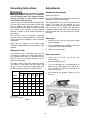
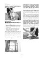
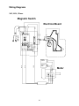
1
This Manual is Bookmarked Operating Instructions and Parts Manual 10-inch Cabinet Saw Model: 2000 Model 2000 Table Saw shown with optional extension table and legs WMH TOOL GROUP 2420 Vantage Drive Elgin, Illinois 60123 Ph.: 800-274-6848 www.wmhtoolgroup.com Part No. M-1791997 Revision B 04/06 Copyright © WMH Tool Group WARRANTY AND SERVICE WMH Tool Group, Inc., warrants every product it sells. If one of our tools needs service or repair, one of our Authorized Service Center located throughout the United States can give you quick service. In most cases, any of these WMH Tool Group Authorized Service Centers can authorize warranty repair, assist you in obtaining parts, or ® perform routine maintenance and major repair on your POWERMATIC tools. For the name of an Authorized Service Center in your area call 1-800-274-6848. MORE INFORMATION WMH Tool Group is consistently adding new products to the line. For complete, up-to-date product information, check with your local WMH Tool Group distributor, or visit powermatic.com. WARRANTY POWERMATIC products carry a limited warranty which varies in duration based upon the product. WHAT IS COVERED? This warranty covers any defects in workmanship or materials subject to the exceptions stated below. Cutting tools, abrasives and other consumables are excluded from warranty coverage. WHO IS COVERED? This warranty covers only the initial purchaser of the product. WHAT IS THE PERIOD OF COVERAGE? The general POWERMATIC warranty lasts for the time period specified in the product literature of each product. WHAT IS NOT COVERED? The Five Year Warranty does not cover products used for commercial, industrial or educational purposes. Products with a Five Year Warranty that are used for commercial, industrial or education purposes revert to a One Year Warranty. This warranty does not cover defects due directly or indirectly to misuse, abuse, negligence or accidents, normal wear-and-tear, improper repair or alterations, or lack of maintenance. HOW TO GET SERVICE The product or part must be returned for examination, postage prepaid, to a location designated by us. For the name of the location nearest you, please call 1-800-274-6848. You must provide proof of initial purchase date and an explanation of the complaint must accompany the merchandise. If our inspection discloses a defect, we will repair or replace the product, or refund the purchase price, at our option. We will return the repaired product or replacement at our expense unless it is determined by us that there is no defect, or that the defect resulted from causes not within the scope of our warranty in which case we will, at your direction, dispose of or return the product. In the event you choose to have the product returned, you will be responsible for the handling and shipping costs of the return. HOW STATE LAW APPLIES This warranty gives you specific legal rights; you may also have other rights which vary from state to state. LIMITATIONS ON THIS WARRANTY WMH TOOL GROUP LIMITS ALL IMPLIED WARRANTIES TO THE PERIOD OF THE LIMITED WARRANTY FOR EACH PRODUCT. EXCEPT AS STATED HEREIN, ANY IMPLIED WARRANTIES OR MERCHANTABILITY AND FITNESS ARE EXCLUDED. SOME STATES DO NOT ALLOW LIMITATIONS ON HOW LONG THE IMPLIED WARRANTY LASTS, SO THE ABOVE LIMITATION MAY NOT APPLY TO YOU. WMH TOOL GROUP SHALL IN NO EVENT BE LIABLE FOR DEATH, INJURIES TO PERSONS OR PROPERTY, OR FOR INCIDENTAL, CONTINGENT, SPECIAL, OR CONSEQUENTIAL DAMAGES ARISING FROM THE USE OF OUR PRODUCTS. SOME STATES DO NOT ALLOW THE EXCLUSION OR LIMITATION OF INCIDENTAL OR CONSEQUENTIAL DAMAGES, SO THE ABOVE LIMITATION OR EXCLUSION MAY NOT APPLY TO YOU. WMH Tool Group sells through distributors only. The specifications in WMH catalogs are given as general information and are not binding. Members of WMH Tool Group reserve the right to effect at any time, without prior notice, those alterations to parts, fittings, and accessory equipment which they may deem necessary for any reason whatsoever. 2 Table of Contents WARRANTY AND SERVICE ........................................................................................................................ 2 Table of Contents.......................................................................................................................................... 3 Warnings ....................................................................................................................................................... 4 Introduction ................................................................................................................................................... 6 Specifications ................................................................................................................................................ 6 Shipping Contents......................................................................................................................................... 7 Unpacking.................................................................................................................................................. 7 Cleaning .................................................................................................................................................... 7 Contents of the Shipping Container .......................................................................................................... 8 Assembly..................................................................................................................................................... 10 Mounting Extension Wings...................................................................................................................... 10 Lock Knobs and Swivel Handles ............................................................................................................. 11 Dust Chute............................................................................................................................................... 11 Blade Installation/Replacement............................................................................................................... 12 Mounting Rails and Accu-Fence............................................................................................................ 12 Optional Wood Extension Table.............................................................................................................. 12 Switch Installation.................................................................................................................................... 12 Riving Knife and Guard Installation ......................................................................................................... 13 Grounding Instructions ................................................................................................................................ 14 Extension Cords ...................................................................................................................................... 14 Zero-Clearance Insert Setup ................................................................................................................... 15 Miter Slot Alignment ................................................................................................................................ 16 Tilt Stop Adjustment ................................................................................................................................ 16 Precision Miter Gauge ............................................................................................................................. 17 Riving Knife Adjustment .......................................................................................................................... 18 Insert Adjustment..................................................................................................................................... 19 Arbor and Arbor Bearing Removal .......................................................................................................... 19 Operating Controls ...................................................................................................................................... 20 Start/Stop................................................................................................................................................. 20 Safety Key ............................................................................................................................................... 20 Motor Cover............................................................................................................................................. 12 Adjustments ................................................................................................................................................ 14 Handwheel Adjustments.......................................................................................................................... 14 Drive Belt ................................................................................................................................................. 17 Operations................................................................................................................................................... 21 Overview.................................................................................................................................................. 21 Kickback .................................................................................................................................................. 21 Bevel and Miter Operations..................................................................................................................... 24 Safety Devices ............................................................................................................................................ 25 Feather Board and Push Blocks.............................................................................................................. 25 Push Stick................................................................................................................................................ 25 Filler Piece............................................................................................................................................... 25 Maintenance................................................................................................................................................ 26 Cleaning .................................................................................................................................................. 26 Lubrication ............................................................................................................................................... 26 Miscellaneous.......................................................................................................................................... 26 Troubleshooting .......................................................................................................................................... 27 Optional Accessories .................................................................................................................................. 28 Ordering Replacement Parts................................................................................................................... 28 Model 2000 Table Saw Parts List ............................................................................................................... 29 Wiring Diagrams.......................................................................................................................................... 38 The specifications in this manual are given as general information and are not binding. WMH Tool Group reserves the right to effect, at any time and without prior notice, changes or alterations to parts, fittings, and accessory equipment deemed necessary for any reason whatsoever. 3 Warnings 1. Read and understand the entire owners manual before attempting assembly or operation. 2. Read and understand the warnings posted on the machine and in this manual. Failure to comply with all of these warnings may cause serious injury. 3. Replace the warning labels if they become obscured or removed. 4. This table saw is designed and intended for use by properly trained and experienced personnel only. If you are not familiar with the proper and safe operation of a table saw, do not use until proper training and knowledge have been obtained. 5. Do not use this table saw for other than its intended use. If used for other purposes, WMH Tool Group disclaims any real or implied warranty and holds itself harmless from any injury that may result from that use. 6. Always wear approved safety glasses/face shields while using this table saw. Everyday eyeglasses only have impact resistant lenses; they are not safety glasses. 7. Before operating this table saw, remove tie, rings, watches and other jewelry, and roll sleeves up past the elbows. Remove all loose clothing and confine long hair. Non-slip footwear or anti-skid floor strips are recommended. Do not wear gloves. 8. Wear ear protectors (plugs or muffs) during extended periods of operation. 9. Some dust created by power sanding, sawing, grinding, drilling and other construction activities contain chemicals known to cause cancer, birth defects or other reproductive harm. Some examples of these chemicals are: • Lead from lead based paint. • Crystalline silica from bricks, cement and other masonry products. • Arsenic and chromium from chemically treated lumber. Your risk of exposure varies, depending on how often you do this type of work. To reduce your exposure to these chemicals, work in a well-ventilated area and work with approved safety equipment, such as face or dust masks that are specifically designed to filter out microscopic particles. 10. Do not operate this machine while tired or under the influence of drugs, alcohol or any medication. 11. Make certain the machine is properly grounded. 12. Make all machine adjustments or maintenance with the machine unplugged from the power source. A machine under repair should be RED TAGGED to show it must not be used until maintenance is complete. 13. Remove adjusting keys and wrenches. Form a habit of checking to see that keys and adjusting wrenches are removed from the machine before turning it on. 14. Keep safety guards in place at all times when the machine is in use. If removed for maintenance purposes, use extreme caution and replace the guards immediately. 15. Check the alignment of the riving knife, fence and miter slot to the blade. A caution decal is installed on each guard to remind the operator of the dangers of improper machine operation. 16. Check damaged parts. Before further use of the machine, a guard or other part that is damaged should be carefully checked to determine that it will operate properly and perform its intended function. Check for alignment of moving parts, binding of moving parts, breakage of parts, mounting and any other conditions that may affect its operation. A guard or other part that is damaged should be properly repaired or replaced. 4 17. Provide for adequate space surrounding work area and non-glare, overhead lighting. 18. Keep the floor around the machine clean and free of scrap material, oil and grease. 19. Keep visitors a safe distance from the work area. Keep children away. 20. Make your workshop child proof with padlocks, master switches or by removing safety keys. 21. Give your work undivided attention. Looking around, carrying on a conversation and “horse-play” are careless acts that can result in serious injury. 22. Maintain a balanced stance at all times so that you do not fall or lean against the blade or other moving parts. Do not overreach or use excessive force to perform any machine operation. 23. Use the right tool at the correct speed and feed rate. Do not force a tool or attachment to do a job for which it was not designed. The right tool will do the job better and safer. 24. Use recommended accessories; improper accessories may be hazardous. 25. Maintain tools with care. Keep blade sharp and clean for the best and safest performance. Follow instructions for lubricating and changing accessories. 26. Check the saw blade for cracks or missing teeth. Do not use a cracked or dull blade or one with missing teeth or improper set. Make sure the blade is securely locked on the arbor. 27. Keep hands clear of the blade area. Do not reach past the blade to clear parts or scrap with the saw blade running. Never saw freehand. Avoid awkward operations and hand positions where a sudden slip could cause your hand to contact the blade. 28. Do not attempt to saw boards with loose knots or with nails or other foreign material, on its surface. Do not attempt to saw twisted, warped, bowed or “in wind” stock unless one edge has been jointed for guiding purposes prior to sawing. 29. Do not attempt to saw long or wide boards unsupported where spring or weight could cause the board to shift position. 30. Always use the riving knife, blade guard, push stick and other safety devices for all operations where they can be used. On operations such as dadoing or molding where the blade guard cannot be used, use feather boards, fixtures and other safety devices and use extreme caution. Reinstall the riving knife and blade guard immediately after completing the operation that required their removal. 31. Be sure the saw blade rotates clockwise when viewed from the motor side (left side) of the machine. 32. Turn off the machine before cleaning. Use a brush or compressed air to remove chips or debris — do not use your hands. 33. Do not stand on the machine. Serious injury could occur if the machine tips over. 34. Never leave the machine running unattended. Turn the power off and do not leave the machine until it comes to a complete stop. 35. Remove loose items and unnecessary work pieces from the area before starting the machine. Familiarize yourself with the following safety notices used in this manual: This means that if precautions are not heeded, it may result in minor injury and/or possible machine damage. This means that if precautions are not heeded, it may result in serious injury or possibly even death. 5 Introduction This manual is provided by WMH Tool Group covering the safe operation and maintenance procedures for a Powermatic Model 2000 Table Saw. This manual contains instructions on installation, safety precautions, general operating procedures, maintenance instructions and parts breakdown. This machine has been designed and constructed to provide years of trouble free operation if used in accordance with instructions set forth in this manual. If there are any questions or comments, please contact either your local supplier or WMH Tool Group. WMH Tool Group can also be reached at our web site: www.wmhtoolgroup.com. Specifications Model number ......................................................................................................................................... 2000 Stock Number 3HP, 230V, 60Hz, 1 Phase, 3600 RPM, TEFC ........................................................................... 1791999 5HP, 230V, 60Hz, 1 Phase, 3600 RPM, TEFC ........................................................................... 1791998 5HP, Prewired 230V (for 460V see Note below), 60Hz, 3 Phase, 3600 RPM, TEFC................. 1791997 Table size with standard extensions (L x W/in.)............................................................................ 42 x 30 1/2 Table size without extensions (L x W/in.)...................................................................................... 22 x 30 1/2 Arbor diameter (in.) .................................................................................................................................... 5/8 Saw blade diameter (in.) ............................................................................................................................. 10 Arbor speed (RPM) ................................................................................................................................. 4300 Left tilt range ........................................................................................................................................... 0–45 Maximum depth of cut (in.)............................................................. 3-1/8 at 90-degrees; 2-1/8 at 45-degrees Maximum diameter of dado (in.) ................................................................................................................... 8 Maximum width of dado cut (in.) ............................................................................................................ 13/16 Drive system ................................................................................................................................. Poly-V Belt Table height to floor (in.) .......................................................................................................................34-1/2 Dust port diameter (in.) ................................................................................................................................. 4 Shipping weight (saw only) ..............................................................All Models: Net: 540 lbs, Gross: 604 lbs Note: For 460V operation, magnetic switch (Part No. PM2000-293C) must be purchased separately and installed. A qualified electrician is recommended. The above specifications were current at the time this manual was published, but because of our policy of continuous improvement, WMH Tool Group reserves the right to change specifications at any time and without prior notice, without incurring obligations. Read and understand the entire contents of this manual before attempting assembly or operation! Failure to comply may cause serious injury 6 Shipping Contents Unpacking Remove box and wood crating completely from around saw. Check for shipping damage. Report any damage immediately to your distributor and shipping agent. Do not discard any shipping material until the Table Saw is assembled and running properly. Compare the contents of your container with the parts lists in the next two pages to make sure all parts are intact. Missing parts, if any, should be reported to your distributor. Read the instruction manual thoroughly for assembly, maintenance and safety instructions. 1. Unbolt the saw from the skid. 2. Carefully slide the saw from the pallet onto the floor. Make sure that the castors do not get damaged when removing from the skid. The Table Saw should be placed in an area with a sturdy level floor, good ventilation and sufficient lighting. Leave enough space around the machine for mounting extension wings and rail assemblies, and loading and off-loading stock and general maintenance work. Cleaning Exposed metal surfaces, such as the table top and extension wings, have been given a protective coating at the factory. This should be removed with a soft cloth moistened with kerosene. Do not use acetone, gasoline, or lacquer thinner for this purpose. Do not use solvents on plastic parts, and do not use an abrasive pad because it may scratch the surfaces. 7 Contents of the Shipping Container Small Box Main Saw Container 1 1 The small box consists of the following items: Table Saw (A) Table Insert (B) 1 1 2 2 1 1 The following items are inside the saw: 1 1 1 1 1 Miter Gauge Assembly (C) Blade Guard Assembly (D) Switch in box (E) Owner's Manual (F) Warranty Card (not shown) Push Stick (G) 27mm Arbor Wrench (H) Lock Knobs (J) Swivel Handles (K) Riving Knife and Pawl Assembly (L) Hardware Bag (M) consisting of: 6 3/8-16 x 1 Hex Cap Screw (AA) 6 3/8 Lock Washer (BB) 6 3/8 Flat Washer (CC) Main Saw Container Contents of the Small Box 8 Extension Tables Two extension tables are packaged in individual boxes. Extension Tables Side Cover Box 2 Hinge Pin (N) 1 Side Cover (O) Contents of Side Cover Box Fence and Rail Carton contents and installation instructions for the fence, rail system, and optional wooden extension table are described in the Accu-Fence Owner's Manual (No. M-0460284). 9 Assembly Mounting Extension Wings Referring to Figure 1: 1. Mount a cast iron extension wing (A) to the right or left side of the table (B) using three each 3/8-16x1 hex head screws (C), 3/8 lock washers (D) and 3/8 flat washers (E). Have an assistant hold the extension wing up to the table while inserting the screws and washers. Finger-tighten only. Note: If an assistant is not available, hold the wing in vertical position up to the saw table, insert the middle screw and lock washer finger tight, then pivot the wing to level position. Insert the other two screws and washers finger tight. Figure 1 2. Mount the remaining extension wing to the other side of the table in the same manner. 3. Make sure that the front edge of the extension wings are flush with the front edge of saw table (Figure 2). Figure 2 4. Level the extension wing with the saw table across its entire width (Figure 3) using a straight edge and hammer with block of wood (or rubber hammer). As each area of the wing becomes flush with the table, tighten the screw under that area. Continue until all three screws are fully tightened. 5. Repeat for the other extension wing. Figure 3 10 Lock Knobs and Swivel Handles Referring to Figure 4: 1. Thread the swivel handles (A) into the front and side handwheels (C) and tighten with a 14mm wrench. 2. Screw lock knobs (B) into the threaded openings on the end of the shafts located in the middle of the handwheels (C). Note: Do not tighten the lock knobs all the way at this time. Figure 4 Dust Chute Referring to Figure 5: The Model 2000 comes equipped with a dust chute and hose assembly (Inset 2) for use with a dust collection system. If you do not intend to use a dust collection system, the dust chute may be disconnected and removed as described below. To provide sufficient clearance for removal of the dust chute: 1. Raise the blade height all the way up and set the blade tilt to 0º (refer to Handwheel Adjustments on page 14). 2. Remove the arbor nut and collar as described in the Blade Installation/Replacement on page 12, steps 3-4. Removing the dust chute: 3. Remove two socket head button screws (D, E) with 4mm and 5mm hex wrenches respectively. 4. Through the opening on the left side of the cabinet, remove the hose (Inset 1, 2) by twisting and pulling back on the dust port (F). Take the entire assembly (Inset 2) out through the side opening. Do not replace the arbor nut and collar at this time, but proceed to the Blade Installation/Replacement section (following page). Figure 5 11 Blade Installation/Replacement Use care when working with or around sharp saw blade to prevent injury! To install or replace a blade (refer to Figure 6): 1. Disconnect machine from power source. 2. Raise the blade height all the way up and set the blade tilt to 0º (refer to Handwheel Adjustments on page 14). 3. Press the arbor lock (D) in the direction shown by the arrow to engage it into the slot in the arbor (C). At the same time remove the arbor nut (loosen with a 27mm wrench if necessary). Figure 6 4. Remove the collar (B). 5. Install the blade, making sure the cutting teeth at the top of the blade point toward the front of the saw. If unsure, refer to Figure 10 for the proper blade orientation. 6. Replace the collar (B) and arbor nut (A). 7. Engage the arbor lock (D) and tighten the nut (A) with a 27mm wrench. 8. Lower the blade below the table. Mounting Rails and Accu-Fence With the extension wings properly aligned, the rail, guide tube and fence assembly can now be mounted to the saw. Consult the Accu-Fence Owner's Manual (Part No. M-0460284) for instructions. Figure 7 Optional Wood Extension Table For instructions on mounting the accessory wood extension table, or router table, consult the Owner's Manual (Part No. Accu-Fence M-0460284) for instructions. Switch Installation Referring to Figure 7: 1. Place the switch assembly (A) under the rail (B) and guide tube (C) so that the two holes in the switch bracket (D) line up with the left two holes in the rail and guide tube. Note: The screws and lock washers may already have been installed when the rail and guide tube were installed and need to be removed for this operation. Figure 8 Motor Cover Line up the door hinges (A. Fig. 8) with the cabinet hinges (B, Fig. 8) and insert hinge pins (C, Fig. 8). Note: The locking mechanism may 2. Secure with two 1/4 lock washers (E) and adjustment to insure proper alignment. 1/4 x 3/4 hex cap screws (F). 12 require Riving Knife and Guard Installation Description Referring to Figure 9: The complete riving knife and guard assembly is shown in A. Before installing onto the saw, the antikickback pawl (E) must be separated from the riving knife (H) as described below. 1. Press and hold the quick-release button (D) on the base of the anti-kickback pawl (E) and lift the pawl to remove from the riving knife (H). Installation Referring to Figure 10: 1. Set the saw blade to the 90 degree position and raise it all the way (refer to Handwheel Adjustments on page 14). 2. Remove the table insert (J). 3. Located inside the table and accessible through the insert opening (Figure 10 inset), place the quick-release clamp lock handle (K) in the unlock position. 4. The floating clamp block (L) is spring loaded and will move away (O) from the fixed block (M), leaving a gap. 5. Insert the bottom of the riving knife (N1, N2) all the way into the gap between the clamp blocks (L, M), then lock the handle (K). 6. Replace the insert (J) back on the table. The saw blade and riving knife should protrude through the slot in the insert. Figure 9 Referring back to Figure 9: 7. Attach the anti-kickback pawl (E) by pressing and holding the quick-release button (D) and inserting the lock pin of the pawl into the appropriate slot (F) on the riving knife. 8. In similar manner attach the guard (C) by pressing and holding the quick-release button (B) and inserting the lock pin of the guard into the appropriate slot (G) on the riving knife. You should feel a snap as each piece locks in position. Attempt to lift as a test to make sure that they are securely locked in place. Adjustment The clamping blocks (L, M, Fig. 10) are adjusted at the factory and no further adjustment of the blade guard and riving knife assembly should be necessary. However, proper alignment is very important. Before operating the table saw, read the Riving Knife Adjustment section (page 18) to verify and follow the adjustment procedure if necessary. 13 Figure 10 Grounding Instructions Adjustments Electrical connections must be made by a qualified electrician in compliance with all relevant codes. This machine must be properly grounded to help prevent electrical shock and possible fatal injury. Handwheel Adjustments A power plug is not provided with the Model 2000. You may either connect the proper UL/CSA listed plug or “hardwire” the machine directly to your electrical panel provided there is a disconnect near the machine for the operator. Consult electrical drawings on pages 37-39 for further clarification of wiring setup. The side handwheel (C) controls the blade tilt and castors. The blade can be adjusted for a tilt between 90º (vertical or a setting of 0º on the scale) and 45º left tilt (D). The Model 2000 also has a retractable castor system that can be extended to permit the table saw to be rolled from one location to another. This machine must be grounded. Grounding provides a path of least resistance to help divert current away from the operator in case of electrical malfunction. Blade height Make sure the voltage of your power supply matches the specifications on the motor plate of the machine. 2. Turn the handwheel (B) clockwise to raise and counterclockwise to lower the blade. Referring to Figure 11: The front handwheel (B) controls the raising and lowering of the blade (blade height). 1. Loosen the lock knob (A) on the blade height adjust handwheel. 3. Tighten the lock knob (A). Extension Cords If an extension cord is necessary, make sure the cord rating is suitable for the amperage listed on the machine's motor plate. An undersize cord will cause a drop in line voltage resulting in loss of power and overheating. The chart in Table 1 shows the correct size cord to use based on cord length and motor plate amp rating. If in doubt, use the next heavier gauge. The smaller the gauge number, the heavier the cord. Extension Cord Length * Amps 25 feet 50 feet 75 feet 100 feet 150 feet 200 feet <5 16 16 16 14 12 12 5 to 8 16 16 14 12 10 NR 8 to 12 14 14 12 10 NR NR 12 to 15 12 12 10 10 NR NR 15 to 20 10 10 10 NR NR NR 21 to 30 10 NR NR NR NR NR Blade tilt adjustment 1. Loosen the lock knob (A) on the side handwheel (C). 2. Push the handwheel in (F). 3. Turn the handwheel (C) counterclockwise to adjust the saw blade down to 45º left tilt (D). Turn clockwise to adjust the saw blade to maximum of 90º (D). 4. After selecting the position, tighten the lock knob (A). *based on limiting the line voltage drop to 5V at 150% of the rated amperes. NR: Not Recommended. Table 1 Figure 11 14 Castor system adjustment Retractable castors can be extended permitting the saw to be moved: 1. Loosen the lock knob (A) on the side handwheel (C). 2. Pull the handwheel out (F). 3. Turn the handwheel (C) clockwise to extend the castors, raising the saw. Note: Because of the weight of the machine, both hands will be needed to turn the handwheel. Raise the saw just enough to permit moving to another location. When the saw has been repositioned: 4. Retract the castors by turning handwheel (C) counterclockwise. the 5. Push the handwheel in (F) and tighten the lock knob (A). Zero-Clearance Insert Setup Under normal operations where the standard table insert (which is provided) is used, the top edge of the saw blade will come to rest approximately 1/8" below the table surface when the blade height is positioned all the way down. In situations where a zero-clearance insert is desired, the saw blade may be lowered further for accommodation of inserts that have potential clearance issues with the blade. This is done as follows: 1. Remove the guard and pawl (Figure 9, Items C, E). 2. Open the side cover and locate the blade depth stop (A, Fig. 12) located between the arbor pulley and motor. Figure 12 3. Using a 6mm hex wrench, loosen the locking screw (B, Fig. 12). 4. This will allow the depth stop to swing free and the saw blade to be adjusted lower. When the standard insert is to be used again, the saw blade must be readjusted as follows: 5. With the height adjust handwheel (B, Fig. 11), lower the saw blade all the way. 6. With the height adjust handwheel (B, Fig. 11), adjust height of the saw until the top of the saw blade is 1/8" below the top of the table. The zero-clearance insert can now be placed into the table opening without contacting the saw blade. Never use a zero-clearance insert with the saw blade in a tilted position. Never operate the saw without the blade guard, riving knife and anti-kickback pawls for operations where they can be used. 7. The blade depth stop (A, Fig. 12) should be resting against the trunnion (C, Fig. 12). Verify that this is the case; then tighten the locking screw (B, Fig. 12). 8. Replace the standard insert, pawl and blade guard. 15 Miter Slot Alignment Disconnect machine from power source before making this adjustment. To check the alignment of the miter slot to the blade: 1. Raise the blade to its maximum height at the 90º vertical position (0º on scale). 2. Mark one tooth with a grease pencil and position the tooth slightly above the top edge of the table at the front. 3. Raise the miter gauge slightly out of its slot to serve as a shoulder. Using a combination square against the side of the bar, slide the scale over until it touches the tip of the blade, and lock the scale in position (A, Fig. 13). 4. Rotate the marked tooth so that it is slightly above the table top at the rear (B, Fig. 13) and using the square as before, check whether the distance to the blade is the same. 5. If the distance is not the same, loosen the four mounting screws that lock the table top to the cabinet (two in front, two in back). 6. Nudge the table to bring the miter slot in line with the blade. The blade must be kept centered with the slot in the table insert to ensure clearance at both the 90º and 45º positions. Figure 13 7. After alignment, secure the table to the cabinet by re-tightening the four mounting screws. Tilt Stop Adjustment 1. Adjust the blade tilt for 90º as described in Blade Tilt Adjustment on page 14. 2. Using a combination square, check the 90º stop (Figure 14 shows the 90º stop being checked). 3. Adjust the 90º stop position if required, using the stop screws as shown. The 90º stop adjustment is accessible though the left side opening. 14mm wrenches are required to loosen the lock nut and adjust the screw. 4. Check the accuracy of the pointer at 0º (blade at 90º vertical position) and adjust if required. 5. Adjust the blade tilt for 45º. If required, adjust the stop and pointer in the same manner. as above. The 45º stop adjustment is accessible though the slot on the front of the cabinet. 16 Figure 14 Precision Miter Gauge 5. Tighten the lock handle (A). Setting the miter gauge angle Verify that the scale indicator (G) reads 0º. If further adjustment is necessary: Referring to Figure 15: The precision miter gauge has a rack and pinion adjustment for setting the angle. To operate: 1. Slide the miter gauge into one of the slots on the table top. 6. Loosen the screw (F) and indicator (G) until it reads 0º adjust the 7. Tighten the screw (F). 2. Loosen lock handle (A). To adjust the body (B) of the miter gauge to the desired angle: 3. Pull the spring-loaded knob (C) out and turn until the body (B) of the miter gauge is at the desired angle as indicated on the scale. 4. Tighten the lock handle (A). Indent settings There are indents at the 0º, 30º and 45º right and left positions. At these settings, release the knob (C) to engage the stop rod. Then tighten the lock handle (A). Note: Do not rely solely on the indents for an accurate setting. After the stop rod engages at the 0º, 30º and 45º positions, make a fine adjustment with the knob (C), if necessary, setting it against the scale indicator. Extension plate The extension plate (D) can be adjusted by sliding to the right or left or removed entirely. To adjust – loosen two lock handles (E), position the extension plate and tighten the lock handles. To remove – slide the extension plate completely off and remove the lock handles (E) and mounting hardware. Calibrating the miter gauge 1. Place the miter gauge in one of the slots (H) on the table top. Figure 15 Drive Belt The saw is equipped with a poly-V belt. Referring to Figure 16: To adjust the belt tension – loosen the hex nut (B) on the motor pivot and hex cap screw (A) on the bracket with a 19mm socket or wrench. Pivot the motor (C) and bracket to the right to increase the belt tension. Retighten both screws (A, B). To remove and replace belt – loosen the hex nut (B) on the motor pivot and hex cap screw (A) on the bracket with a 19mm socket or wrench. Pivot the motor (C) and bracket to the left as far as possible. Remove the old poly-V belt (D) and replace. Adjust the belt tension as described above. 2. Set the miter gauge to 90º (0º setting on the scale) by loosening the lock handle (A), then pulling the spring-loaded knob (C) out and turning the body (B) until 0º is indicated on the scale (F). 3. Measure the accuracy of the gauge against the slot with a combination square. If adjustment is necessary: 4. Adjust the body (B) until it is perfectly square (90º) to the miter slot (H). Figure 16 17 Riving Knife Adjustment Lateral alignment The saw blade and riving knife must be in line as close as possible with each other (lateral alignment) for the prevention of kickback. Upon initial blade guard and riving knife installation no further adjustment should be necessary. Alignment should be checked and adjusted, if required, after each blade change. Check the alignment as follows: 1. Remove the blade guard and pawl (C, E, Fig. 9). 2. Place a straightedge (A, Fig. 17) on the table so it rests against the blade (B, Fig 17) and riving knife (C, Fig. 17). Rotate the blade so the top of the blade tooth touches the straightedge. Figure 17 The saw blade and riving knife must be in line. If adjustment is required: 3. Remove the blade guard (C, Fig. 9) and table insert. 4. Loosen the lock handle (A, Fig. 18) and remove the riving knife, making a note as to which direction the riving knife needs to be moved to align it with the saw blade. 5. Using a 3mm hex wrench, make adjustments to four set screws (D, Fig. 19) accessible through openings located in the corners of the floating clamp block (B, Fig. 19). Adjust any number of setscrews required to bring the riving knife in alignment with the saw blade. Then reinsert the riving knife, secure by tightening the lock handle (A, Fig. 18) and check the alignment per step 2. Figure 18 Note: Position the lock handle towards the saw blade as shown in Figure 18. This will avoid the table insert from being lifted when the blade is raised with the handwheel. 6. Repeat steps 3–5 until the alignment is correct. Blade proximity alignment The gap between the saw blade and riving knife must be between 3 and 8mm (Figure 20). If adjustment is needed, note whether the blade to knife gap needs to be increased or decreased. Then adjust as follows: 1. Remove the blade guard, pawl, table insert and riving knife. Referring to Figure 19: 2. With a 5mm hex wrench, loosen two socket head button screws (E). 18 Figure 19 Note: These screws are accessible through openings on the floating clamp block (B) located diagonally on either side of the lock handle (A). They secure the fixed clamp block (C) to the riving knife extension plate (F). Loosening these screws (E) will allow the fixed clamp block (C) to slide back and forth on the extension plate (F). 3. Slide the fixed clamp block (F) toward or away from the saw blade as required. 4. Tighten the socket head button screws (E). 5. Reinsert the riving knife; tighten the lock handle (A, Fig. 18) and check that the saw blade/knife gap is between 3 - 8mm (Figure 20). Figure 20 Note: Attempt to make the gaps as even as possible. Insert Adjustment Adjust the setscrews in the insert with a 3mm hex wrench (Figure 21) to ensure that the insert is stable and flush with the table top. Figure 21 Arbor and Arbor Bearing Removal The saw arbor is press fit in the saw raising arm housing. If the arbor needs to be removed for bearing replacement, it should be done by a qualified service technician. Call your customer service representative at the phone number on the front cover. 19 Operating Controls Start/Stop Power Indicator Light – The start switch has a power indicator lamp which is on whenever there is power connected to the saw, not just when the saw is running. Do not assume that no light means there is no power to the machine. If the bulb is bad, there will no indication. Always check before use. Do not rely that no light means no power to the machine. Always check for power first. Failure to comply may cause serious injury! Referring to Figure 22: Start – Press the green start switch. When power is connected to the machine, the green light is always on regardless of whether the saw is running or not. Figure 22 Stop – Press the red switch to stop. Reset – In the event that the saw stops without pressing the stop button, as the result of a tripped fuse or circuit breaker, etc.: 1. Press red button to reset 2. Press the green button to restart the machine. Safety Key The start/stop switch on the Model 2000 comes equipped with a magnetic safety key. When in place on the switch as shown in Figure 22, the magnetic safety key trips a relay which will allow the machine to start and stop when the respective switches are pressed. Being magnetic, the lock can be removed to make the machine inoperable and can be hidden for safe storage by attaching it underneath the rail or an other magnetic surface. When using the saw, place the key on the switch cover lining up the arrow on the key with the REMOVE arrow on the cover. Then rotate the key so the arrow lines up with the LOCK arrow. This will prevent the safety key from coming loose from vibration when the machine is in use. 20 Operations Overview Familiarize yourself with the location and operation of all controls and adjustments and the use of accessories such as the miter gauge and rip fence. Kickback Serious injury can result from kickbacks which occur when a work piece binds on the saw blade or binds between the saw blade and rip fence or other fixed object. This binding can cause the work piece to lift up and be thrown toward the operator. Figure 23 Dull, badly set, improper, or improperly filed cutting tools and cutting tools with gum or resin adhering to them can cause accidents. Never use a cracked saw blade. The use of a sharp, well maintained, and correct cutting tool for the operation will help to avoid injuries. Listed below are conditions, which can cause kickbacks: • Confining the cutoff piece when crosscutting or ripping. • Releasing the work piece before completing the operation or not pushing the work piece all the way past the saw blade. • Not using the riving knife when ripping or not maintaining alignment of the riving knife with the saw blade. • Using a dull saw blade. • Not maintaining alignment of the rip fence so that it tends to angle toward rather than away from the saw blade front to back. • Applying feed force when ripping to the cutoff (free) section of the work piece instead of the section between the saw blade and fence. • Ripping wood that is twisted (not flat), or does not have a straight edge, or a twisted grain. To minimize or prevent injury from kickbacks: • • • • • Support the work properly and hold it firmly against the gauge or fence. Use a push stick or push block when ripping short, narrow (6" width or less), or thin work. Use a push block or miter gauge holddown when dadoing or molding. For increased safety in crosscutting, use the provided extension plate (Figure 24) attached to the miter gauge using the holes provided in the gauge. Avoid conditions listed above. Wear a safety face shield, goggles, or glasses. Do not use the miter gauge and rip fence in the same operation unless provision is made by use of a facing board on the fence so as to allow the cutoff section of the workpiece to come free before the next cut is started (see Figure 30). As the machine receives use, the operation of the anti-kickback pawls should be checked periodically (Figure 23). If the pawls do not stop the reverse motion of a workpiece, resharpen all the points. Where possible, keep your face and body out of line with potential kickbacks including when starting or stopping the machine. Figure 24 Never use the fence as a length stop when crosscutting. Do not hold or touch the free end or cutoff section of a workpiece. On throughsawing operations, the cutoff section must NOT be confined. Always keep your hands out of the line of the saw blade and never reach back of the cutting blade with either hand to hold the workpiece. Bevel ripping cuts should always be made with the fence on the right side of the saw blade so that the blade tilts away from the fence and minimizes the possibility of the work binding and the resulting kickback. 21 Rip Sawing The rip fence (A, Fig. 26) should be set for the width of the cut (C, Fig. 26) by using the scale on the front rail, or by measuring the distance between the blade (B) and fence (A). Stand out of line with the saw blade and workpiece to avoid sawdust and splinters coming off the blade or a kickback, if one should occur. Ripping is where the work piece is fed with the grain into the saw blade using the fence as a guide and a positioning device to ensure the desired width of cut (Figure 25). If the work piece does not have a straight edge, attach an auxiliary straight edged board on it to provide one against the fence. To cut properly, the board must make good contact with the table. In ripping, use one hand to hold the board down against the fence or fixture, and the other to push it into the blade between the blade and the fence. If the workpiece is narrower than 6" or shorter than 12", use a push stick or push block to push it through between the fence and saw blade (Figure 27). Never push in a location such that the pushing hand is in line with the blade. Move the hand serving as a hold-down a safe distance from the blade as the cut nears completion. For very narrow ripping where a push stick cannot be used, use a push block or auxiliary fence. Always push the workpiece completely past the blade at the end of a cut to minimize the possibility of a kickback. Figure 25 Before starting a ripping cut, be sure the fence is clamped securely and aligned properly. • Never rip freehand or use the miter gauge in combination with the fence. • Never rip workpieces shorter than the saw blade diameter. • Never reach behind the blade with either hand to hold down or remove the cutoff piece with the saw blade rotating. Always use the blade guard, riving knife and anti-kickback pawls. Make sure the riving knife is properly aligned. When wood is cut along the grain, the kerf tends to close and bind on the blade and kickbacks can occur. Note: A caution decal is installed on each guard to remind the operator of the dangers of improper machine operation. Figure 27 Figure 26 22 Crosscutting should never be done freehand nor should the fence be used as an end stop unless an auxiliary block is clamped to the front of the blade area such that the cutoff piece comes free of the block before cutting starts (Figure 30). When ripping long boards, use a support at the front of the table, such as a roller stand, and a support or "tailman" at the rear as shown in Figure 28. Never use the rip fence beyond the point where the carriage is flush with the end of the rails. Have the blade extend about 1/8" above the top of the workpiece. Exposing the blade above this point can be hazardous. Figure 30 Length stops should not be used on the free end of the workpiece in the cutoff area. Do not crosscut workpieces shorter than 6". Before starting a cut, be sure the miter gauge is securely clamped at the desired angle. Hold the workpiece firmly against the table and back against the miter gauge. Always use the saw guard and riving knife and make sure the riving knife is properly aligned. Figure 28 Crosscutting For 90 degree crosscutting, most operators prefer to use the left-hand miter gauge slot. When using it in this position, hold the workpiece against the gauge with the left hand and use the right hand to advance the workpiece. When using the right hand slot for miter and compound crosscutting so that the blade tilts away from the gauge, the hand positions are reversed. Crosscutting is where the workpiece is fed cross grain into the saw blade using the miter gauge to support and position the workpiece (Figure 29). When using the miter gauge, the workpiece must be held firmly and advanced smoothly at a slow rate. If the workpiece is not held firmly, it can vibrate causing it to bind on the blade and dull the saw teeth. Figure 29 23 Bevel and Miter Operations Dado Cutting – Dadoing is cutting a wide groove into a workpiece or cutting a rabbet along the edge of a workpiece. A dado insert, shown in Figure 33, is necessary for this type of operation. Bevel Cut – A bevel cut is a special type of operation where the saw blade is tilted at an angle less than 90 degrees to the table top (Figure 31). Operations are performed in the same manner as ripping or crosscutting except the fence or miter gauge should be used on the right-hand side of the saw blade to provide added safety in avoiding a binding action between the saw blade and the table top. When beveling with the miter gauge, the workpiece must be held firmly to prevent creeping. Do not use the standard table insert for dadoing operations. Figure 33 The process of cutting 1/8" to 13/16" grooves in workpieces is accomplished by the use of a stacked dado blade set or an adjustable type blade mounted on the saw arbor. By using various combinations of the stacked dado blades, or properly setting the dial on an adjustable blade, an accurate width dado can be made. This is very useful for shelving, making joints, tenoning, etc. The guard, riving knife, and anti-kickback pawls supplied with the saw should be used for all cutting operations where they can be used. When performing operations where the guard can not be used, as in some dadoing operations, alternative safety precautions should be taken. These include push sticks, feather boards, filler pieces, fixtures, jigs and any other appropriate device that can be utilized to keep operator's hands away from the blade. Upon completion of the operation requiring removal of the guard, the entire guard assembly must be placed back on the machine in its proper working order. Figure 31 Crosscut – Crosscuts made at an angle to the edge of the workpiece are called miters (Figure 32). Set the miter gauge at the required angle, lock the miter gauge, and make the cut the same as a normal crosscut except the workpiece must be held extra firmly to prevent creeping. Note: When making compound miters (with blade tilted) use the miter gauge in the right hand slot to provide more hand clearance and safety. Have the blade extend only 1/8" above the top of the workpiece. Exposing the blade above this point can be hazardous. Never use a dado head in a tilted position. Never operate the saw without the blade guard, riving knife and antikickback pawls for operations where they can be used. Figure 32 24 Safety Devices Feather Board and Push Blocks A feather board or push block is not provided but can be purchased by calling customer service at the number shown on the cover and ordering stock number 709721 (feather board) or 708815 (push block). In addition, a multitude of after market products are available that can be used in conjunction with the miter slot and fence. These can be purchased at most woodworking stores that sell table saws and accessories. Push Stick The use of a push stick provides an added level of safety for the operator and is provided with this machine. Filler Piece Figure 34 – Filler Piece A filler piece (Figure 34) is necessary for narrow ripping and permits the blade guard to remain on the machine. It also provides space for the safe use of a push stick. 25 Maintenance Always disconnect power to the machine before performing maintenance. Failure to do this may result in serious personal injury. Cleaning • Keep the inside of the cabinet and trunnion area clean. Note: The following maintenance schedule assumes the saw is being used every day. • Check for excessive play in the tilting and raising mechanism and in the saw arbor and re-adjust as required. • Check for belt tension and wear. Readjust or replace belt as required. Daily: • Wipe down the table surface and grooves with a rust preventive. • Clean the pitch and resin from the saw blade. Weekly: Lubrication • Grease the tilting worm gear, raising worm gear, castor system worm gear and the trunnion areas with a good grade nonhardening grease. • Check all adjustments after lubricating. • Table surface must be kept clean and free of rust for best results. Apply a coat of paste wax to the surface to facilitate this. An alternative is to apply white talcum powder, rubbed in vigorously once a week with a blackboard eraser; this will fill casting pores and form a moisture barrier. This method provides a table top that is slick and allows rust rings to be easily wiped from the surface. Important also is the fact that talcum powder will not stain wood or mar finishes as wax pickup does. • Clean the motor housing with compressed air. • Wipe down the fence rails with a dry silicon lubricant. Periodic: Miscellaneous Always be aware of the condition of your machine. Routinely check the condition of the following items and repair or replace as necessary: • • • • 26 Mounting bolts Power switch Saw blade Blade guard assembly Troubleshooting Trouble Excessive vibration. Cuts out-of-square when crosscutting. Motor stalls or workpiece binds or burns. Cuts not true at 90 or 45 degrees. Tilt or saw raising handwheels difficult to turn. Probable Cause Remedy Tilt or raising clamp knobs not tightened. Tighten knobs. Blade out of balance. Change blade. [page 12] Bad motor. Replace motor. Loose arbor or motor sheave. Tighten set screws. Miter gauge out of adjustment. Reset pointer. [page 17] Miter slot misaligned. Realign table. [page 16] Excessive feed. Reduce feed. Bad motor. Replace motor. Dull or incorrect blade. Replace blade. [page 12] Miter slot misaligned. Realign miter slot. [page 16] Fence misalignment. Realign fence. [see Fence Manual No. M-0460284] Stop screws not set properly. Readjust stop screws. [page 16] Lock knob not released. Loosen lock knob. Worm and worm gear segment caked with sawdust and pitch. Clean and re-grease. Worm and worm gear segment out of alignment. Realign worm and worm gear segment. Motor overloaded. Correct overload condition such as reducing the feed rate. Improper cooling of motor. Clean sawdust from fan and duct areas of motor. Low voltage. Request voltage check from power company and correct low voltage condition. Centrifugal switch not operating. Replace switch. Bad motor. Replace motor. Power line overloaded. Correct overload condition. Undersize wires in supply system. Increase supply wire size. Low voltage. Request voltage check from power company and correct condition. Bad motor. Replace motor. Motor overheats. Motor starts slowly or fails to come up to speed. Motor fails to develop full power. 27 Optional Accessories 2195042K Accu-Fence and rail system for ripping 50" to right and 12" to left of saw blade. 2195079Z Accu-Fence - fence assembly only, no rails. 2195063K Accu-Fence and rail system for ripping 30" to right and 12" to left of saw blade. 1791787 Low Profile Riving Knife. 1791790 Table Insert. 1791788 Dado Insert Plate for 8" dado head. Wt. 1 lb. (.45 kg). 2726008 Replacement side panel kit for Model 66 Accu-Fence. 1791789 Miter Gauge. Wt. 4 lbs. (1.8kg). 6827044 Motor cover. 708295 Tenoning Jig. 2328003 Zero Clearance Insert. 6441000Z Set of 2 legs for 6827028 table. 6682004 Rout-R-Lift with deluxe fence. 6827041 Wooden Extension Table for 50" capacity with Rout-R-Lift hole. 6827043 Wooden Extension Table for 30" capacity with Rout-R-Lift hole. 6827040 Wooden Extension Table for 50" capacity without Rout-R-Lift hole. 6827042 Wooden Extension Table for 30" capacity without Rout-R-Lift hole. Ordering Replacement Parts To order parts or reach our service department, call 1-800-274-6848 between 7:30am and 5:30pm (CST), Monday through Friday. Having the Model Number and Serial Number of your machine available when you call will allow us to serve you quickly and accurately. 28 Model 2000 Table Saw Parts List Table & Cabinet Assembly Index No. Part No. Description Size Qty 1 ...............PM2000-101 ............Base ..................................................................... .................................... 1 2 ...............PM2000-102 ............Cabinet................................................................. .................................... 1 3 ...............TS-0255041 .............Button Head Socket Screw .................................. 5/16-18x3/4................. 8 4 ...............TS-0680031 .............Flat Washer.......................................................... 5/16 ............................. 8 5 ...............PM2000-105 ............Powermatic Name Plate ...................................... .................................... 1 6 ...............PM2000-106 ............Button Head Socket Screw .................................. 5/16-18x3/8................. 2 7 ...............PM2000-107 ............Lock Screw........................................................... .................................... 2 8 ...............TS-081C011.............Flat Head Machine Screw.................................... #10-24x1/4.................. 2 9 ...............PM2000-109 ............Pointer.................................................................. .................................... 2 10 .............PM2000-110 ............Pointer Block ........................................................ .................................... 2 11 .............TS-081C032.............Pan Head Screw .................................................. #10-24x1/2.................. 2 12 .............PM2000-112 ............Tilt Angle Scale .................................................... .................................... 1 13 .............TS-0254021 .............Button Head Socket Screw .................................. 1/4-20x1/2................... 2 14 .............PM2000-114 ............Scale Base ........................................................... .................................... 1 15 .............PM2000-115 ............Latch Post ............................................................ .................................... 1 16 .............TS-0561021 .............Hex Nut ................................................................ 5/16-18........................ 1 17 .............PM2000-117 ............Dust Plate............................................................. .................................... 1 18 .............PM2000-118 ............Bushing ................................................................ .................................... 1 19 .............TS-0050011 .............Hex Cap Screw .................................................... 1/4-20x1/2................... 4 20 .............TS-0680021 .............Flat Washer.......................................................... 1/4 ............................... 6 21 .............PM2000-121 ............Dust Port .............................................................. .................................... 1 22 .............TS-0267021 .............Set Screw............................................................. 1/4-20x1/4................. 13 23 .............1791790 ...................Table Insert .......................................................... .................................... 1 24 .............PM2000-124 ............Ball Plunger.......................................................... .................................... 2 25 .............PM2000-125 ............Table .................................................................... .................................... 1 26 .............PM2000-126 ............Extension Table ................................................... .................................... 2 27 .............TS-0680041 .............Flat Washer.......................................................... 3/8 ............................. 10 28 .............TS-0720091 .............Lock Washer ........................................................ 3/8 ............................. 10 29 .............TS-0720071 .............Flat Washer.......................................................... 1/4 ............................... 2 30 .............PM2000-130 ............Strain Relief.......................................................... .................................... 1 .................PM2000-130A ..........Strain Relief (for 5HP/1Ph only)........................... .................................... 1 31 .............TS-0060061 .............Hex Cap Screw .................................................... 3/8-16x1.................... 10 32 .............PM2000-132 ............Dust Chute ........................................................... .................................... 1 33 .............TS-0720081 .............Lock Washer ........................................................ 5/16 ............................. 4 34 .............TS-0255021 .............Button Head Socket Screw .................................. 5/16-18x1/2................. 4 35 .............PM2000-135 ............Push Stick ............................................................ .................................... 1 36 .............PM2000-136 ............Retaining Ring ..................................................... .................................... 5 37 .............PM2000-137 ............Key ....................................................................... 5x5x18 ........................ 4 38 .............PM2000-138 ............Sprocket ............................................................... .................................... 5 39 .............TS-0208131 .............Socket Head Cap Screw...................................... 5/16-18x2-1/2.............. 8 40 .............BB-6904ZZ...............Ball Bearing.......................................................... 6904ZZ........................ 3 41 .............PM2000-141 ............Shaft..................................................................... .................................... 3 42 .............PM2000-142 ............Lead Screw .......................................................... .................................... 1 43 .............PM2000-143 ............Adjusting Block .................................................... .................................... 4 44 .............TS-0640111 .............Nylon Insert Lock Nut........................................... 1/2-13.......................... 4 45 .............PM2000-145 ............Elevating Block .................................................... .................................... 4 46 .............PM2000-146 ............Castor................................................................... .................................... 4 47 .............PM2000-147 ............Bracket ................................................................. .................................... 1 48 .............BB-51104 .................Thrust Bearing ..................................................... 51104 .......................... 1 49 .............PM2000-149 ............Chain.................................................................... .................................... 1 50 .............PM2000-150 ............Dust Collection Tube............................................ .................................... 1 29 Table & Cabinet Parts Assembly 30 Trunnion & Motor Assembly Parts List Index No. Part No. Description Size Qty 1 ...............PM2000-201 ............Knob..................................................................... .................................... 2 2 ...............PM2000-202 ............Hand Wheel ......................................................... .................................... 2 3 ...............TS-0270051 .............Set Screw............................................................. 5/16-18x1/2................. 2 4 ...............PM2000-204 ............Collar.................................................................... .................................... 1 5 ...............TS-0270011 .............Set Screw............................................................. 5/16-18x1/4................. 4 6 ...............PM2000-206 ............Washer................................................................. .................................... 2 7 ...............TS-0810012 .............Round Head Screw.............................................. #10-24x1/4.................. 1 8 ...............PM2000-208 ............Pointer.................................................................. .................................... 1 9 ...............PM2000-209 ............Bracket ................................................................. .................................... 1 10 .............PM2000-210 ............Roll Pin................................................................. .................................... 1 11 .............TS-0271131 .............Set Screw............................................................. 3/8-16x2...................... 1 12 .............TS-0561031 .............Hex Nut ................................................................ 3/8-16........................ 14 13 .............PM2000-213 ............Front Trunnion ..................................................... .................................... 1 14 .............TS-0267041 .............Set Screw............................................................. 1/4-20x3/8................... 9 15 .............PM2000-215 ............Key ....................................................................... 5x5x25 ........................ 3 16 .............PM2000-216 ............Worm Gear........................................................... .................................... 1 17 .............TS-0256051 .............Button Head Socket Screw .................................. 3/8-16x1...................... 8 18 .............PM2000-218 ............Lock Nut ............................................................... 5/8-18 L.H. .................. 1 19 .............PM2000-219 ............Support Base ....................................................... .................................... 1 20 .............PM2000-220 ............Raising Shaft........................................................ .................................... 1 21 .............PM2000-221 ............Woodruff Key ....................................................... .................................... 2 22 .............PM2000-222 ............Roll Pin................................................................. .................................... 3 23 .............PM2000-223 ............Bushing ................................................................ .................................... 1 24 .............PM2000-224 ............Worm.................................................................... .................................... 2 25 .............PM2000-225 ............Shaft..................................................................... .................................... 1 26 .............PM2000-226 ............Bushing ................................................................ .................................... 1 27 .............PM2000-227 ............Worm.................................................................... .................................... 1 28 .............TS-0209061 .............Socket Head Cap Screw...................................... 3/8-16x1-1/4................ 9 29 .............TS-0680041 .............Flat Washer.......................................................... 3/8 ............................... 3 30 .............TS-0720091 .............Lock Washer ........................................................ 3/8 ............................. 18 31 .............PM2000-231 ............Bracket ................................................................. .................................... 1 32 .............PM2000-232 ............Flat Head Machined Screw.................................. 1/4-20x3/4................... 2 33 .............TS-0254031 .............Button Head Socket Screw .................................. 1/4-20x3/4................... 1 34 .............PM2000-234 ............Shaft..................................................................... .................................... 1 35 .............TS-0060061 .............Hex Cap Screw .................................................... 3/8-16x1-1/4................ 2 36 .............PM2000-236 ............Washer................................................................. .................................... 2 37 .............PM2000-237 ............Lock Nut ............................................................... 1-1/8-12 ...................... 1 38 .............PM2000-238 ............Center Trunnion ................................................... .................................... 1 39 .............PM2000-239 ............Poly-V Belt ........................................................... .................................... 1 40 .............PM2000-240 ............Key ....................................................................... 7x7x25 ........................ 1 41 .............PM2000-241 ............Motor Pulley ......................................................... .................................... 1 42 .............TS-0270031 .............Set Screw............................................................. 5/16-18x3/8................. 4 43 .............PM2000-243 ............Motor Base........................................................... .................................... 1 44 .............PM2000-244 ............Stud...................................................................... .................................... 1 45 .............TS-0680061 .............Flat Washer.......................................................... 1/2 ............................... 2 46 .............TS-0640111 .............Nylon Insert Lock Nut........................................... 1/2-13.......................... 2 47 .............TS-0070031 .............Hex Cap Screw .................................................... 1/2-13x1-1/2................ 1 48 .............PM2000-248 ............Motor ................................................................... 3HP, 230V, 1Ph .......... 1 .................PM2000-MF .............Motor Fan (not shown)......................................... .................................... 1 .................PM2000-MFC...........Motor Fan Cover (not shown) .............................. .................................... 1 .................PM2000-CS .............Centrifugal Switch (not shown) ............................ .................................... 1 .................PM2000-SC .............Starting Capacitor (not shown) ............................ 250MFD, 250VAC....... 1 .................PM2000-RC .............Running Capacitor (not shown) ........................... 20µF, 450VAC ............ 1 .................PM2000-SCC...........Starting Capacitor Cover (not shown).................. .................................... 1 .................PM2000-RCC...........Running Capacitor Cover (not shown)................. .................................... 1 .................PM2000-JB ..............Junction Box (not shown)..................................... .................................... 1 31 Trunnion & Motor Assembly Parts List Index No. Part No. Description Size Qty .................PM2000-JBC............Junction Box Cover (not shown) .......................... .................................... 1 .................PM2000-248A ..........Motor ................................................................... 5HP, 230V, 1Ph .......... 1 .................PM2000-MF .............Motor Fan (not shown)......................................... .................................... 1 .................PM2000-MFCA ........Motor Fan Cover (not shown) .............................. .................................... 1 .................PM2000-CSA ...........Centrifugal Switch (not shown) ............................ .................................... 1 .................PM2000-SCA ...........Starting Capacitor (not shown) ............................ 400MFD, 250VAC....... 1 .................PM2000-RCA...........Running Capacitor (not shown) ........................... 35µF, 450VAC ............ 1 .................PM2000-SCCA ........Staring Capacitor Cover (not shown)................... .................................... 1 .................PM2000-RCCA ........Running Capacitor Cover (not shown)................. .................................... 1 .................PM2000-JBA............Junction Box (not shown)..................................... .................................... 1 .................PM2000-JBC............Junction Box Cover (not shown) .......................... .................................... 1 .................PM2000-248B ..........Motor ................................................................... 5HP, 230/460V, 3Ph ... 1 .................PM2000-MF .............Motor Fan (not shown)......................................... .................................... 1 .................PM2000-MFCA ........Motor Fan Cover (not shown) .............................. .................................... 1 .................PM2000-JB ..............Junction Box (not shown)..................................... .................................... 1 .................PM2000-JBC............Junction Box Cover (not shown) .......................... .................................... 1 49 .............PM2000-249 ............Shaft..................................................................... .................................... 1 50 .............PM2000-250 ............Retaining Ring ..................................................... .................................... 1 51 .............PM2000-251 ............Shoulder Screw.................................................... .................................... 4 52 .............PM2000-252 ............Extension Support Bracket .................................. .................................... 1 53 .............TS-0680031 .............Flat Washer.......................................................... 5/16 ............................. 2 54 .............PM2000-254 ............Bearing Arm ......................................................... .................................... 1 55 .............PM2000-255 ............Gear Block ........................................................... .................................... 1 56 .............TS-0680041 .............Flat Washer.......................................................... 3/8 ............................... 3 57 .............TS-0060071 .............Hex Cap Screw .................................................... 3/8-16x1-1/2................ 1 58 .............TS-0060091 .............Hex Cap Screw .................................................... 3/8-16x2...................... 1 59 .............TS-0255041 .............Button Head Socket Screw .................................. 5/16-18x3/4................. 4 60 .............PM2000-260 ............Blade Dust Chute................................................. .................................... 1 61 .............PM2000-261 ............Arbor Nut.............................................................. .................................... 1 62 .............PM2000-262 ............Arbor Collar .......................................................... .................................... 1 63 .............PM2000-263 ............Spring................................................................... .................................... 1 64 .............PM2000-264 ............Arbor .................................................................... .................................... 1 .................PM2000-AA..............Arbor Assembly (Index #61, #62, #64, #78 thru #80) 65 .............PM2000-265 ............Fixed Plate ........................................................... .................................... 1 66 .............PM2000-266 ............Riving Knife Extension Plate................................ .................................... 1 67 .............PM2000-267 ............Clamping Block ................................................... .................................... 1 68 .............PM2000-268 ............Clamping Block .................................................... .................................... 1 69 .............PM2000-269 ............Lock Handle ......................................................... .................................... 1 70 .............PM2000-270 ............Locking Pin........................................................... .................................... 1 71 .............PM2000-271 ............Roll Pin ................................................................ .................................... 1 72 .............PM2000-272 ............Rear Trunnion ...................................................... .................................... 1 73 .............TS-0271051 .............Set Screw............................................................. 3/8-16x1/2................... 1 74 .............TS-081C032.............Pan Head Screw .................................................. #10-24x1/2.................. 4 75 .............PM2000-275 ............Plate ..................................................................... .................................... 1 76 .............PM2000-276 ............Arbor Lock Insert.................................................. .................................... 1 77 .............PM2000-277 ............Spring................................................................... .................................... 1 78 .............PM2000-278 ............Bushing ................................................................ .................................... 1 79 .............BB-6204VV ..............Ball Bearing.......................................................... 6204VV ....................... 2 80 .............PM2000-280 ............Bushing ................................................................ .................................... 1 81 .............PM2000-281 ............Arbor Pulley.......................................................... .................................... 1 82 .............TS-0640091 .............Nylon Insert Lock Nut........................................... 3/8-16.......................... 1 83 .............PM2000-283 ............Shaft..................................................................... .................................... 1 84 .............BB-6003ZZ...............Ball Bearing.......................................................... 6003ZZ........................ 1 85 .............PM2000-285 ............Stop Block ............................................................ .................................... 1 86 .............PM2000-286 ............Washer................................................................. .................................... 1 87 .............PM2000-287 ............Bushing ................................................................ .................................... 1 32 Trunnion & Motor Assembly Parts List Index No. Part No. Description Size Qty 88 .............PM2000-288 ............DU Bushing .......................................................... .................................... 1 89 .............PM2000-289 ............Retaining Ring ..................................................... .................................... 1 90 .............PM2000-290 ............Retaining Ring ..................................................... .................................... 1 91 .............TS-0720081 .............Lock Washer ........................................................ 5/16 ............................. 2 92 .............PM2000-292 ............Switch Plate ......................................................... .................................... 1 93 .............PM2000-293 ............Magnetic Switch................................................... 3HP, 230V, 1Ph .......... 1 .................PM2000-293A ..........Magnetic Switch................................................... 5HP, 230V, 1Ph .......... 1 .................PM2000-293B ..........Magnetic Switch................................................... 5HP, 230V, 3Ph .......... 1 .................PM2000-293C..........Magnetic Switch................................................... 5HP, 460V, 3Ph .......... 1 94 .............PM2000-294 ............Strain Relief.......................................................... .................................... 2 .................PM2000-294A ..........Strain Relief (for 5HP/1Ph only)........................... .................................... 1 95 .............PM2000-295 ............Power Cord (for 3HP/1Ph) ................................... .................................... 1 .................PM2000-295A ..........Power Cord (for 5HP/1Ph) ................................... .................................... 1 .................PM2000-295B ..........Power Cord (for 5HP/3Ph) ................................... .................................... 1 96 .............PM2000-296 ............Motor Cord (for 3HP/1Ph) .................................... .................................... 1 .................PM2000-296A ..........Motor Cord (for 5HP/1Ph) .................................... .................................... 1 .................PM2000-296B ..........Motor Cord (for 5HP/3Ph) .................................... .................................... 1 97 .............TS-0270101 .............Set Screw............................................................. 5/16-18x1-1/4.............. 2 98 .............PM2000-298 ............Safety Key for Magnetic Switch ........................... .................................... 1 99 .............PM2000-299 ............Bearing Washer ................................................... .................................... 2 100 ...........BB-6805ZZ...............Ball Bearing.......................................................... 6805ZZ........................ 1 101 ...........TS-0271091 .............Set Screw............................................................. 3/8-16x1...................... 1 102 ...........TS-0254022 .............Button Head Socket Screw .................................. 1/4-20x1/2................... 2 33 Trunnion & Motor Assembly 34 Blade Guard & Miter Gauge Assembly Parts List Index No. Part No. Description Size Qty 1 ...............PM2000-301 ............Riving Knife ......................................................... .................................... 1 .................PM2000-BGA...........Blade Guard Assembly (Index #2 thru #16, #21, #22) ............................. 1 2 ...............PM2000-302 ............Bushing ................................................................ .................................... 2 3 ...............PM2000-303 ............Blade Guard Body................................................ .................................... 1 4 ...............PM2000-304 ............Blade Guard Side Shield...................................... .................................... 2 5 ...............PM2000-305 ............Linking Plate......................................................... .................................... 4 6 ...............TS-1550041 .............Flat Washer.......................................................... M6 ............................... 8 7 ...............TS-1514021 .............Flat Head Socket Screw ...................................... M6x16 ......................... 8 8 ...............PM2000-308 ............Front Shield.......................................................... .................................... 1 9 ...............PM2000-309 ............Bushing ................................................................ .................................... 1 10 .............PM2000-310 ............Top Sight Shield................................................... .................................... 1 11 .............TS-1541021 .............Nylon Insert Lock Nut........................................... M6 ............................... 8 12 .............TS-081B012.............Pan Head Screw .................................................. #8-32x1/4.................... 2 13 .............PM2000-313 ............Roll Pin................................................................. 5x25 ............................ 1 14 .............PM2000-314 ............Roll Pin................................................................. 5x12 ............................ 2 15 .............PM2000-315 ............Lock Pin ............................................................... .................................... 1 16 .............PM2000-316 ............Roll Pin................................................................. 4x30 ............................ 1 .................PM2000-AKPA.........Anti-Kickback Pawl Assembly (Index #17 thru #22) ................................ 1 17 .............PM2000-317 ............Anti-Kickback Pawl .............................................. .................................... 2 18 .............PM2000-318 ............Pawl Base ............................................................ .................................... 1 19 .............PM2000-319 ............Flange .................................................................. .................................... 2 20 .............PM2000-320 ............Lock Pin ............................................................... .................................... 1 21 .............PM2000-321 ............Spring................................................................... .................................... 2 22 .............PM2000-322 ............E-Clip ................................................................... .................................... 2 .................1791789 ...................Miter Gauge Assembly (Index #23 thru #42) ....... .................................... 1 23 .............PM2000-323 ............Miter Gauge Body ................................................ .................................... 1 24 .............PM2000-324 ............Pin ........................................................................ .................................... 1 25 .............PM2000-325 ............Miter Bar............................................................... .................................... 1 26 .............PM2000-326 ............Guide Washer ...................................................... .................................... 1 27 .............PM2000-327 ............Flat Head Machine Screw.................................... M6x9 ........................... 1 28 .............TS-0050051 .............Hex Cap Screw .................................................... 1/4-20x1...................... 2 29 .............PM2000-329 ............Socket Head Cap Screw...................................... M5x8 ........................... 2 30 .............PM2000-330 ............Support Base ....................................................... .................................... 1 31 .............PM2000-331 ............Knob..................................................................... .................................... 1 32 .............TS-1521011 .............Set Screw............................................................. M4x4 ........................... 1 33 .............PM2000-333 ............Locking Handle .................................................... .................................... 2 34 .............TS-0810012 .............Round Head Screw.............................................. #10-24x1/4.................. 1 35 .............PM2000-335 ............Pointer.................................................................. .................................... 1 36 .............PM2000-336 ............Spring................................................................... .................................... 1 37 .............PM2000-337 ............Gear Shaft............................................................ .................................... 1 38 .............PM2000-338 ............Scale .................................................................... .................................... 1 39 .............PM2000-339 ............Rivet ..................................................................... .................................... 2 40 .............PM2000-340 ............Handle.................................................................. .................................... 1 41 .............TS-0680031 .............Flat Washer.......................................................... 5/16 ............................. 1 42 .............PM2000-342 ............Fence ................................................................... .................................... 1 35 Blade Guard & Miter Gauge Assembly 36 Side Cover Assembly Index No. Part No. Description Size Qty .................6827044 ...................PM2000 Motor Cover Assembly (Index #1 thru #9).................................. 1 1 ...............PM2000-401 ............Cover.................................................................... .................................... 1 2 ...............PM2000-402 ............Hinge Pin.............................................................. .................................... 2 3 ...............PM2000-403 ............Bracket ................................................................. .................................... 1 4 ...............PM2000-404 ............Latch Clip ............................................................. .................................... 1 5 ...............PM2000-405 ............Button Head Socket Screw .................................. 1/4-20x1-1/4................ 1 6 ...............TS-0640071 .............Nylon Insert Lock Nut........................................... 1/4-20.......................... 1 7 ...............TS-081C032.............Pan Head Screw .................................................. #10-24x1/2.................. 1 8 ...............TS-069204 ...............Flat Washer.......................................................... #10 .............................. 1 9 ...............TS-0560071 .............Hex Nut ................................................................ #10-24......................... 1 37 Wiring Diagrams 3HP, 230V, 1Phase Magnetic Switch 5L3 13NO BLACK WHIET RED 6T3 14NO YELLOW 4T2 YELLOW BLACK 4T2 6T3 98 97 96 95 C LED R RED 2T1 GREEN A2 2T1 GROUND WHITE 450VAC 20UF 38 WHITE BLACK Motor GREEN GREEN BLACK 250VAC 250MFD WHITE BLACK GREEN 1L2 3L2 WHITE A1 WHITE BLACK GREEN Electrical Board 5HP, 230V, 1Phase Magnetic Switch 5L3 13NO BLACK WHIET RED 6T3 14NO YELLOW 4T2 YELLOW BLACK A2 2T1 GROUND WHITE 6T3 98 97 96 95 R RED 4T2 C LED GREEN 2T1 450VAC 35UF 39 WHITE BLACK Motor GREEN GREEN BLACK 250VAC 400MFD WHITE BLACK GREEN 1L2 3L2 WHITE A1 WHITE BLACK GREEN Electrical Board 5HP, 230V, 3Phase Magnetic Switch GREEN BLACK BLACK RED 40 Y1 X1 W2 V2 U2 W1 V1 U1 WHITE Z1 RED 95 GREEN BLACK 97 96 R RED 6T3 98 RED GREEN 4T2 C GREEN 2T1 LED BLACK 6T3 14NO YELLOW 4T2 YELLOW BLACK A2 2T1 GROUND WHITE WHITE RED 5L3 13NO WHIET BLACK GREEN 1L2 3L2 WHITE A1 WHITE RED Electrical Board Motor 5HP, 460V, 3Phase Magnetic Switch GREEN BLACK 5L3 13NO BLACK 3L2 WHIET RED 41 Y1 X1 W2 V2 U2 W1 V1 U1 WHITE Z1 RED 95 GREEN BLACK 97 96 R RED 6T3 98 RED GREEN 4T2 C GREEN 2T1 LED BLACK 6T3 14NO YELLOW 4T2 YELLOW BLACK A2 2T1 GROUND WHITE WHITE BLACK RED GREEN 1L2 WHITE A1 WHITE RED Electrical Board Motor Notes 42 Notes 43 WMH Tool Group 2420 Vantage Drive Elgin, Illinois 60123 Phone: 800-274-6848 www.wmhtoolgroup.com 44