1
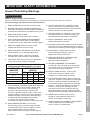
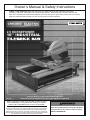
Owner’s Manual & Safety Instructions
Save This Manual Keep this manual for the safety warnings and precautions, assembly,
operating, inspection, maintenance and cleaning procedures. Write the product’s serial number in the
back of the manual near the assembly diagram (or month and year of purchase if product has no number).
Keep this manual and the receipt in a safe and dry place for future reference.
2.5 HORSEPOWER
10" INDUSTRIAL
TILE/BRICK SAW
REV 14h
Blade and stand sold separately.
Visit our website at: http://www.harborfreight.com
Email our technical support at: [email protected]
When unpacking, make sure that the product is intact
and undamaged. If any parts are missing or broken,
please call 1-888-866-5797 as soon as possible.
Copyright© 2011 by Harbor Freight Tools®. All rights reserved.
No portion of this manual or any artwork contained herein may be reproduced in
any shape or form without the express written consent of Harbor Freight Tools.
Diagrams within this manual may not be drawn proportionally. Due to continuing
improvements, actual product may differ slightly from the product described herein.
Tools required for assembly and service may not be included.
Read this material before using this product.
Failure to do so can result in serious injury.
SAVE THIS MANUAL.
Table of Contents
SAFETY
Safety.......................................................... 2
Specifications.............................................. 8
Setup........................................................... 9
Operation.................................................... 12
Maintenance............................................... 15
Parts Lists and Diagram............................. 17
Warranty..................................................... 20
SETUP
WARNING SYMBOLS AND DEFINITIONS
This is the safety alert symbol. It is used to alert you to potential personal injury hazards.
Obey all safety messages that follow this symbol to avoid possible injury or death.
Indicates a hazardous situation which, if not avoided,
will result in death or serious injury.
Indicates a hazardous situation which, if not avoided,
could result in death or serious injury.
Indicates a hazardous situation which, if not avoided,
could result in minor or moderate injury.
OPERATION
Addresses practices not related to personal injury.
MAINTENANCE
Page 2
For technical questions, please call 1-888-866-5797.
Item 69275
IMPORTANT SAFETY INFORMATION
SAFETY
General Tool Safety Warnings
Read all safety warnings and instructions.
Failure to follow the warnings and instructions may result in electric shock, fire and/or serious injury.
Save all warnings and instructions for future reference.
12. SECURE WORK. Use clamps or a vise to hold
work when practical. It’s safer than using your
hand and it frees both hands to operate tool.
4. DON’T USE IN DANGEROUS ENVIRONMENT.
Don’t use power tools in damp or wet locations,
or expose them to rain. Keep work area well lighted.
13. DON’T OVERREACH. Keep proper
footing and balance at all times.
5. KEEP CHILDREN AWAY. All visitors should
be kept safe distance from work area.
6. MAKE WORKSHOP KID PROOF with padlocks,
master switches, or by removing starter keys.
7. DON’T FORCE TOOL. It will do the job better
and safer at the rate for which it was designed.
8. USE RIGHT TOOL. Don’t force tool or attachment
to do a job for which it was not designed.
Table A: RECOMMENDED MINIMUM WIRE
GAUGE FOR EXTENSION CORDS (120 VOLT)
NAMEPLATE
AMPERES
(at full load)
EXTENSION CORD
LENGTH
25′
50′ 100′ 150′
0–6
18
16
16
14
6.1 – 10
18
16
14
12
10.1 – 12
16
16
14
12
12.1 – 16
14
12
Do not use.
9. USE PROPER EXTENSION CORD. Make sure your
extension cord is in good condition. When using
an extension cord, be sure to use one heavy
enough to carry the current your product will
draw. An undersized cord will cause a drop in line
voltage resulting in loss of power and overheating.
Table A shows the correct size to use depending
on cord length and nameplate ampere rating.
If in doubt, use the next heavier gauge.
The smaller the gauge number, the heavier the cord.
10. WEAR PROPER APPAREL. Do not wear
loose clothing, gloves, neckties, rings, bracelets,
or other jewelry which may get caught in moving
parts. Nonslip footwear is recommended.
Wear protective hair covering to contain long hair.
Item 69275
14. MAINTAIN TOOLS WITH CARE. Keep tools sharp
and clean for best and safest performance. Follow
instructions for lubricating and changing accessories.
SETUP
3. KEEP WORK AREA CLEAN.
Cluttered areas and benches invite accidents.
15. DISCONNECT TOOLS before servicing;
when changing accessories, such as
blades, bits, cutters, and the like.
16. REDUCE THE RISK OF UNINTENTIONAL
STARTING. Make sure switch is in
off position before plugging in.
17. USE RECOMMENDED ACCESSORIES.
Consult the owner’s manual for recommended
accessories. The use of improper accessories
may cause risk of injury to persons.
18. NEVER STAND ON TOOL. Serious injury
could occur if the tool is tipped or if the
cutting tool is unintentionally contacted.
19. CHECK DAMAGED PARTS. Before further use
of the tool, a guard or other part that is damaged
should be carefully checked to determine that
it will operate properly and perform its intended
function – check for alignment of moving parts,
binding of moving parts, breakage of parts,
mounting, and any other conditions that may
affect its operation. A guard or other part that is
damaged should be properly repaired or replaced.
20. DIRECTION OF FEED. Feed work into
a blade or cutter against the direction of
rotation of the blade or cutter only.
21. NEVER LEAVE TOOL RUNNING UNATTENDED.
TURN POWER OFF. Don’t leave tool
until it comes to a complete stop.
For technical questions, please call 1-888-866-5797.
Page 3
OPERATION
2. REMOVE ADJUSTING KEYS AND WRENCHES.
Form habit of checking to see that keys and adjusting
wrenches are removed from tool before turning it on.
11. ALWAYS USE SAFETY GLASSES. Also use
face or dust mask if cutting operation is dusty.
Everyday eyeglasses only have impact resistant
lenses, they are NOT safety glasses.
MAINTENANCE
1. KEEP GUARDS IN PLACE and in working order.
Grounding Instructions
SAFETY
TO PREVENT ELECTRIC SHOCK AND DEATH FROM INCORRECT GROUNDING WIRE CONNECTION
READ AND FOLLOW THESE INSTRUCTIONS:
110-120 VAC Grounded Tools: Tools with Three Prong Plugs
1. In the event of a malfunction or breakdown,
grounding provides a path of least resistance for
electric current to reduce the risk of electric shock.
This tool is equipped with an electric cord having an
equipment-grounding conductor and a grounding
plug. The plug must be plugged into a matching
outlet that is properly installed and grounded in
accordance with all local codes and ordinances.
SETUP
2. Do not modify the plug provided – if it will
not fit the outlet, have the proper outlet
installed by a qualified electrician.
3. Improper connection of the equipment-grounding
conductor can result in a risk of electric shock.
The conductor with insulation having an outer
surface that is green with or without yellow
stripes is the equipment-grounding conductor.
If repair or replacement of the electric cord or
plug is necessary, do not connect the equipmentgrounding conductor to a live terminal.
OPERATION
4. Check with a qualified electrician or service
personnel if the grounding instructions are
not completely understood, or if in doubt as
to whether the tool is properly grounded.
5. Use only 3-wire extension cords that
have 3-prong grounding plugs and 3-pole
receptacles that accept the tool’s plug.
6. Repair or replace damaged or worn cord immediately.
Grounding
Pin
Figure A: 125 VAC 3-Prong Plug and Outlet
(for up to 125 VAC and up to 15 A)
7. This tool is intended for use on a circuit that has
an outlet that looks like the one illustrated above
in Figure A: 125 VAC 3-Prong Plug and Outlet.
The tool has a grounding plug
that looks like the plug illustrated above in
Figure A: 125 VAC 3-Prong Plug and Outlet.
8. The outlet must be properly installed and grounded
in accordance with all codes and ordinances.
9. Do not use an adapter to connect
this tool to a different outlet.
MAINTENANCE
Page 4
For technical questions, please call 1-888-866-5797.
Item 69275
Tile Saw Safety Warnings
3. Keep hands out of the line of saw blade.
4. Use an appropriate push-stick when required.
5. Know how to reduce risk of kickback.
6. Do not perform any operation freehand.
7. Never reach around or over saw blade.
8. Make sure the workpiece is supported at all
times while sawing. Use a roller stand (not
provided) with larger workpieces if necessary.
9. To properly understand all safety warnings, be familiar
with the following safety terms and equipment:
a. Featherboard – A block with “fingers” that hold
the workpiece against the fence while sawing.
b. Through-sawing – A cut made from one side of the
workpiece to the opposite side, without stopping.
c. Push-stick – A narrow strip of wood or other soft
material with a notch cut into one end and which
is used to push short pieces of material through
saws. It provides a safe distance between the
hands and the cutting tool. Must be narrower than
the cut width to prevent contact with the blade.
d. Freehand – Feeding a workpiece through the
saw without using a fence or guided support
to guide it. NOT A SAFE METHOD.
e. Kerf – The gap made by the saw in the workpiece.
g. Spreader – A metal plate that follows the
saw blade to keep the kerf (gap) from closing
on the saw blade. Spreaders, except riving
knives, must be aligned to the blade after
blade adjustment to prevent binding.
10. As noted previously, Kickback is a sudden reaction
to a pinched, bound, or misaligned blade, causing an
uncontrolled workpiece to lift up and out of the saw
toward the operator.
Kickback is usually a result of tool misuse and can be
limited or avoided by following the precautions below:
• Fence must be completely
parallel to the saw blade.
SETUP
2. Use saw-blade guard and spreader
for every operation for which it can be
used, including all through sawing.
f. Kickback – A sudden reaction to a pinched,
bound, or misaligned blade, causing
an uncontrolled workpiece to lift up and
out of the saw toward the operator.
• Workpiece must be free from flaws
and from foreign objects.
• Support large workpieces along their
entire length. Large workpieces tend
to bend, grabbing the blade.
• Maintain control of the workpiece. Do not
allow the workpiece to rest against the
moving blade without holding onto it.
• If the blade binds or a cut is interrupted, turn
off the power switch and hold the workpiece
still until the blade stops. Correct the cause
of blade binding before proceeding.
11. Check guards for proper operation with saw
disconnected from power before each use.
Do not disable any guard. Do not operate
saw if any movable guard does not move
freely and close instantly. Make sure any
movable guard does not touch the blade in
all angles, depths of cut, and positions.
OPERATION
1. Wear eye protection.
SAFETY
For Your Own Safety Read Instruction Manual Before Operating Saw
MAINTENANCE
12. Keep the guard in place while throughsawing. Verify that the spreader lines up
with the blade to prevent binding.
Item 69275
For technical questions, please call 1-888-866-5797.
Page 5
Tile Saw Safety Warnings (cont.)
POSITION OF TILE SAW
EXTENSION CORDS
Tile Saw
SAFETY
Power Cord
Drip Loop
SETUP
Figure B: Drip Loop
13. To avoid the possibility of the tool plug or
receptacle getting wet, position tile saw to one
side of a wall mounted receptacle to prevent
water from dripping onto the receptacle or plug.
The user should arrange a “drip loop” in the cord
connecting the saw to a receptacle. The “drip loop”
is that part of the cord below the level of the
receptacle, or the connector if an extension cord
is used, to prevent water traveling along the cord
and coming in contact with the receptacle.
16. Use only extension cords that are intended for
outdoor use. These extension cords are identified
by a marking “Acceptable for use with outdoor
tools; store indoors while not in use.” Use only
extension cords having an electrical rating not
less than the rating of the product. Do not use
damaged extension cords. Examine extension
cord before using and replace if damaged.
Do not abuse extension cords and do not yank
on any cord to disconnect. Keep cord away
from heat and sharp edges. Always disconnect
the extension cord from the receptacle before
disconnecting the product from the extension cord.
17. WARNING – To reduce the risk of electrocution,
keep all connections dry and off the ground.
Do not touch plug with wet hands.
18. Ground Fault Circuit Interrupter (GFCI) protection
should be provided on the circuit(s) or outlet(s)
to be used for the tile saw. Receptacles are
available having built-in GFCI protection and
may be used for this measure of safety.
OPERATION
14. If the plug or receptacle does get wet, DON’T unplug
the cord. Disconnect the fuse or circuit breaker
that supplies power to the tool. Then unplug and
examine for presence of water in the receptacle.
Tile Saw
Power Cord
Drip Loop
Extension
Cord
MAINTENANCE
Figure C: Extension Cord Drip Loop
15. If an extension cord is used, the drip loop must be
before the cord connection and the extension cord
connection must be placed on an elevated surface.
Page 6
For technical questions, please call 1-888-866-5797.
Item 69275
20. The use of accessories or attachments not
recommended by the manufacturer may
result in a risk of injury to persons.
21. When servicing use only identical replacement parts.
22. Do not depress the spindle lock when
starting or during operation.
23. Only use safety equipment that has been approved
by an appropriate standards agency. Unapproved
safety equipment may not provide adequate
protection. Eye protection must be ANSI-approved
and breathing protection must be NIOSH-approved
for the specific hazards in the work area.
24. Stay alert, watch what you are doing and use
common sense when operating a power tool.
Do not use a power tool while you are tired or
under the influence of drugs, alcohol or medication.
A moment of inattention while operating power
tools may result in serious personal injury.
25. Industrial applications must follow OSHA guidelines.
26. Maintain labels and nameplates on the tool.
These carry important safety information.
If unreadable or missing, contact
Harbor Freight Tools for a replacement.
30. WARNING: The cord of this product contains
lead and/or di (2-ethylhexyl) phthalate (DEHP),
chemicals known to the State of California
to cause cancer, and birth defects or other
reproductive harm. Wash hands after handling.
(California Health & Safety Code § 25249.5, et seq.)
31. The warnings, precautions, and instructions
discussed in this instruction manual cannot
cover all possible conditions and situations
that may occur. It must be understood by the
operator that common sense and caution are
factors which cannot be built into this product,
but must be supplied by the operator.
MAINTENANCE
27. Avoid unintentional starting.
Prepare to begin work before turning on the tool.
29. WARNING: Some dust created by power sanding,
sawing, grinding, drilling, and other construction
activities, contains chemicals known to the State
of California to cause cancer and birth defects or
other reproductive harm. Some examples of these
chemicals are:
• Lead from lead-based paints
• Crystalline silica from bricks and cement or other
masonry products
• Arsenic and chromium from chemically
treated lumber
Your risk from these exposures varies, depending
on how often you do this type of work. To reduce
your exposure to these chemicals: work in a well
ventilated area, and work with approved safety
equipment, such as those dust masks that are
specially designed to filter out microscopic particles.
(California Health & Safety Code § 25249.5, et seq.)
SETUP
19. DO NOT OPERATE WITH ANY GUARD DISABLED,
DAMAGED, OR REMOVED. Moving guards
must move freely and close instantly.
28. People with pacemakers should consult their
physician(s) before use. Electromagnetic fields in
close proximity to heart pacemaker could cause
pacemaker interference or pacemaker failure.
OPERATION
ADDITIONAL TILE SAW SAFETY WARNINGS
SAFETY
Tile Saw Safety Warnings (cont.)
Item 69275
For technical questions, please call 1-888-866-5797.
Page 7
Vibration Safety
This tool vibrates during use. Repeated or long-term
exposure to vibration may cause temporary or permanent
physical injury, particularly to the hands, arms and
shoulders. To reduce the risk of vibration-related injury:
SAFETY
1. Anyone using vibrating tools regularly or for an
extended period should first be examined by a
doctor and then have regular medical check‑ups
to ensure medical problems are not being caused
or worsened from use. Pregnant women or
people who have impaired blood circulation to
the hand, past hand injuries, nervous system
disorders, diabetes, or Raynaud’s Disease should
not use this tool. If you feel any medical or
physical symptoms related to vibration (such as
tingling, numbness, and white or blue fingers),
seek medical advice as soon as possible.
2. Do not smoke during use. Nicotine reduces
the blood supply to the hands and fingers,
increasing the risk of vibration-related injury.
3. Use tools with the lowest vibration when there
is a choice between different processes.
4. Include vibration-free periods each day of work.
5. Grip tool as lightly as possible (while still keeping
safe control of it). Let the tool do the work.
6. To reduce vibration, maintain the tool as
explained in this manual. If any abnormal
vibration occurs, stop use immediately.
SETUP
SAVE THESE INSTRUCTIONS.
Specifications
OPERATION
Electrical Rating
120VAC / 15A
Motor No Load Speed
4,000 RPM
Max. Blade Diameter
10″
Arbor Diameter
5/8″
Max. Cutting Depth
3-1/2″ @ 0º
1-1/2″ @ 45º
Max. Cutting Length
24″
Max Diagonal Tile Size
18″
Bevel Cutting Range
0º, 22.5º, 45º
184892
MAINTENANCE
Page 8
For technical questions, please call 1-888-866-5797.
Item 69275
Setup - Before Use:
Read the ENTIRE IMPORTANT SAFETY INFORMATION section at the beginning of this
manual including all text under subheadings therein before set up or use of this product.
Depth
Lock
Miter
Gauge
SETUP
Table
Lock
Lever
Toggle
Table Stop
Pump
Power
Cord
Drain
Plug
Water
Tray
Table
Stop
Water Tray
Frame
OPERATION
Table
Pump
Bracket
Stand
(sold separately)
Power Switch: The Power Switch includes a Key
for safety. The Tile Saw switch cannot be turned
on without the key. Remove the Key after use.
Reset Button: Directly above the Power Switch is
the Reset Button. If the Tile Saw overheats it will shut
down automatically. Allow it to cool down, make sure
there are no loose connections or damaged cords,
and then press the Reset Button to restart the Saw.
Do not force workpieces into the saw and make sure
the blade is properly wetted to reduce overheating.
Item 69275
Toggle Table Stop: This allows the Table to be
removed if needed. Lift the Stop and turn it to
lock/unlock. If the slot is aligned with the Table,
the Table can be removed. If the slot is turned
sideways, the Table is locked into the saw.
Table Lock Lever: To lock the Table in place, line up this
Lever′s pin with the hole in the rail, and press the Lever
towards the rail. Pull out on the Lever to unlock the Table.
For technical questions, please call 1-888-866-5797.
Page 9
MAINTENANCE
Power
Switch
& Key
Pump Outlet
Bevel Lock
Lever
Blade
(sold separately)
Reset
Button
Power
Cord
Depth Stop
Guard
Lock
Depth
Knob
SAFETY
Functions
ASSEMBLY
SAFETY
TO PREVENT SERIOUS INJURY FROM ACCIDENTAL OPERATION:
Turn the Power Switch of the tool to its “OFF” position, remove the key, and unplug the tool
from its electrical outlet before assembling or making any adjustments to the tool.
Note: For additional information regarding the parts listed in the following pages,
refer to the Assembly Diagram near the end of this manual.
Installing the Water Tray Frame to the Leg Stand
Water Tray
Frame
1. Lock the Toggle Table Stop by pulling up on it
and turning it until the slot in the center of
the Stop is horizontal (left to right).
SETUP
2. Pull the Table to the front of the Frame.
From under the right side of the Table, align the
hole in the rail with the pin in the Table Lock Lever.
Push the pin into the rail, locking the Table.
3. Align the holes on the Water Tray Frame with
the holes on the Stand (sold separately).
4. Insert Short Bolts through Washers
and into holes. Tighten securely.
Washer
Short
Bolt
Stand
Figure D: Water Tray Frame Installation
OPERATION
Installing Motor Head and Water Tray Frame
1. Install Handle to end of Water Tray Frame
using Bolts (119) and Washers.
Short
Bolt
2. Align the holes in the Motor Head assembly with
the holes on the side of the Water Tray Frame.
Motor
Head
Long
Bolt
3. Insert two Short Bolts through Washers,
and then into holes on side of Motor Head.
Loosely secure using Lock Nuts.
MAINTENANCE
4. Insert four Long Bolts through Lock Washers
and Washers. Insert into holes on end of
Water Tray Frame, as shown. Finger tighten.
5. Tighten all Bolts securely.
Page 10
Lock
Washer
Washer
Water
Tray Frame
Lock
Nut
Handle
Figure E: Motor Head Installation
For technical questions, please call 1-888-866-5797.
Item 69275
Installing the Particle Tray
1. Unlock the Table Lock Lever. Lift and turn the
Toggle Table Stop so that its slot aligns with the Table.
Figure F: Particle Tray
Table
SAFETY
2. Pull the Table to the front of the Water Tray Frame.
3. Slide the Particle Tray into the Grooves
on the underside of the Table.
4. Return the Table to its working position,
and lift then turn the Toggle Table Stop
so that its slot aligns sideways.
Grooves
Particle Tray
1. From the right side of the saw, place the
Water Tray (drain plug end to the left) on the
lip at the bottom of the Water Tray Frame.
Water Tray
Frame
SETUP
Water Tray and Pump Setup
2. Slide the Water Tray in under the Table
until it rests in place within the tabs.
Water Tray
3. Adjust the flow control on the
Pump to the desired level.
OPERATION
Figure G: Water Tray Installation
4. Place the Pump into the Pump Bracket in the
Pump Basin. It should fit securely into the Bracket.
6. Make sure your hands are dry and the Tile Saw
is unplugged, then attach the Pump Power
Cord to the Pump Outlet on the Motor Head.
7. Fill the Water Tray with clean water up to the
Maximum Fill Line (see Figure H) before every use.
CAUTION: Water level must be kept above Minimum
Fill Line at all times during operation or damage
to the Pump and/or Saw Blade will occur.
Item 69275
Pump
Outlet
Hose Connector
Pump
Power
Cord
Drain Plug
Minimum
Fill Line
Pump
Maximum
Fill Line
Pump
Basin
Water
Tray
Figure H: Pump setup
For technical questions, please call 1-888-866-5797.
Page 11
MAINTENANCE
5. Connect the clear water Hose from under the arm of
the Motor Head to the Hose Connector on the Pump.
Operating Instructions
Read the ENTIRE IMPORTANT SAFETY INFORMATION section at the beginning of this
manual including all text under subheadings therein before set up or use of this product.
SAFETY
TOOL SET UP
TO PREVENT SERIOUS INJURY FROM ACCIDENTAL OPERATION:
Turn the Power Switch of the tool to its “OFF” position, remove the key, and unplug the tool
from its electrical outlet before assembling or making any adjustments to the tool.
TO PREVENT SERIOUS INJURY:
DO NOT OPERATE WITH ANY GUARD DISABLED, DAMAGED, OR REMOVED.
Installing Blade
1. Unplug the saw.
SETUP
Inner
Flange
2. Turn the Guard Knob counterclockwise.
Outer
Flange
3. Open the Guard to expose the Spindle.
4. Loosen the Spindle Nut counterclockwise
and remove the old Blade, if installed.
Spindle
Nut
Blade
5. Place the Inner Flange onto the Spindle.
Install with the cupped side of the
Inner Flange facing the tile saw housing.
Figure I: Blade Assembly
OPERATION
6. Wipe a drop of oil onto the Inner Flange
where it will contact the Blade.
Spindle
Lock
WARNING! TO PREVENT SERIOUS INJURY:
Only use a smooth rim, wet cutting, 10″ Blade rated
to at least 4,000 RPM on this tool.
Do not use a Blade that is too thick to allow Outer Flange
to engage with the flats on the Spindle.
Do not use a Blade that has openings, grooves, or teeth.
Blade
Guard
Guard
Knob
7. Slide the Blade (sold separately) onto Spindle.
8. Place Outer Flange onto the Spindle.
The flats on the Outer Washer align with the
flats on the Spindle. Install with the cupped
side of the Outer Flange facing the blade.
MAINTENANCE
9. Place Spindle Nut on Spindle.
Wrench
Figure J: Securing Blade
10. Press and hold the Spindle Lock in.
11. Wrench-tighten Spindle Nut securely.
Release the Spindle Lock.
12. Close the Guard, and use the
Guard Knob to secure it.
Page 12
For technical questions, please call 1-888-866-5797.
Item 69275
Miter Adjustment
Miter Lock
Lever
1. Place the slot on the underside of the
Miter Gauge on the Table Fence.
Miter Gauge
Gauge
Lock
Knob
2. Lock the Miter Gauge securely to the table by
turning the Gauge Lock Knob clockwise.
3. To adjust angles:
SAFETY
Note: The Miter Gauge can be used from
either the left or the right side of the Blade.
Table
Fence
a. Loosen the Miter Lock Lever.
b. Set to the desired angle by moving
the Guide left or right.
c. Tighten the Miter Lock Lever securely
before turning on the saw.
Figure K: Miter Gauge
SETUP
Bevel Adjustment
1. Slide the Table clear of the Blade
to prevent blade damage.
2. Loosen the Bevel Lock Lever.
3. Adjust the Motor Head to the desired angle:
0º, 22.5º or 45º. Do not set bevel to
any other setting, the slots in the table
are designed only for these cuts.
Bevel Lock
Lever
Figure L: Bevel Lock Lever
4. Tighten the Bevel Lock Lever.
2. Depth Knob: The Depth Knob can be used to
lock the Motor Head at a particular cutting depth;
tighten it to lock the Motor Head in place,
loosen it to allow adjustment.
3. Depth Stop: This controls the maximum cut depth.
If the blade cuts too deeply or too shallowly;
loosen the Depth Stop Lock, adjust the Depth Stop,
and tighten the Depth Stop Lock again.
Depth Stop
Depth Knob
Depth Stop
Lock
Depth
Lock
Figure M: Depth Controls
Work Piece and Work Area Set Up
1. Designate a work area that is clean and well‑lit.
The work area must not allow access by children
or pets to prevent distraction and injury.
2. Route the power cord along a safe route to reach
the work area without creating a tripping hazard
or exposing the power cord to possible damage.
The power cord must reach the work area with
enough extra length to allow free movement
while working. Set up the Power Cord with a drip
loop, see Position of Tile Saw on page 6.
Item 69275
3. There must not be objects, such as utility lines,
nearby that will present a hazard while working.
4. Keep workpieces pressed firmly against
the Table and Fence while cutting.
5. Mark cut lines using waterproof marker or crayon.
Note: This tool is intended for use on
man‑made masonry and tile products only.
For technical questions, please call 1-888-866-5797.
Page 13
MAINTENANCE
1. Depth Lock: Use the Depth Lock to lock the
Motor Head in the down position; press it in while
the Motor Head is down to lock, and pull out
while holding down the Motor Head to unlock.
OPERATION
Depth Adjustment
General Operating Instructions
1. Fill the Water Tray with clean
water up to the Maximum Fill Line
(see Figure H on page 11) before every use.
SAFETY
CAUTION: Water level must be kept above Minimum
Fill Line at all times during operation or damage
to the Pump and/or Saw Blade will occur.
2. Adjust the Miter, Bevel, and Depth
settings as needed, see previous page.
Lock all settings in place.
Figure N: Straight Cut
SETUP
3. Place the workpiece on the Table and firmly
against the Miter Gauge and Fence.
4. Make sure the workpiece is clear of the Blade,
then dry your hands, plug in the Saw, insert the Key
and turn the Power Switch to the ON position.
OPERATION
5. Make sure the pump is supplying enough water
to the Blade. If needed, dry your hands, unplug
the Saw, adjust the Pump′s flow control, dry
your hands again, and plug the Saw back in.
Figure O: Miter Cut
6. Let the Blade build up to full speed before cutting.
7. Hold the material firmly against the rip guide
and feed the material into the Blade.
MAINTENANCE
8. When the cut is made, turn the Saw OFF.
Wait for the Blade to come to a complete stop
before removing any part of the workpiece.
9. To prevent accidents, turn off the Saw, remove the
Key, and unplug the Tile Saw after use. Clean,
then store the Saw indoors out of children’s reach.
Page 14
Figure P: Bevel Cut
For technical questions, please call 1-888-866-5797.
Item 69275
Maintenance and Servicing
SAFETY
Procedures not specifically explained in this manual must
be performed only by a qualified technician.
TO PREVENT SERIOUS INJURY FROM ACCIDENTAL OPERATION:
Turn the Power Switch of the tool to its “OFF” position, remove the key, and unplug the tool from
its electrical outlet before performing any inspection, maintenance, or cleaning procedures.
TO PREVENT SERIOUS INJURY FROM TOOL FAILURE:
Do not use damaged equipment. If abnormal noise or vibration
occurs, have the problem corrected before further use.
1. BEFORE EACH USE, inspect the general condition
of the tool. Check for loose hardware, misalignment
or binding of moving parts, cracked or broken parts,
damaged electrical wiring, and any other
condition that may affect its safe operation.
2. AFTER USE, wipe external surfaces of the tool
with clean cloth. Also, clean the following after
every use, and as needed during extended use:
3. If Blade is out of alignment, Table does not
slide smoothly or other issues interfere with
smooth operation, have the saw serviced by
a qualified technician before further use.
4.
SETUP
Cleaning, Maintenance, and Lubrication
WARNING! If the supply cord of this
power tool is damaged, it must be replaced
only by a qualified service technician.
• Rails
• Particle Tray (see page 11)
OPERATION
• Water Tray (see page 11,
empty out sediment and water)
MAINTENANCE
• Pump filter and housing (see page 11,
can often be rinsed off without opening pump).
Item 69275
For technical questions, please call 1-888-866-5797.
Page 15
Troubleshooting
Problem
Possible Causes
Likely Solutions
Tool will not start. 1. Cord not connected.
2. No power at outlet.
SAFETY
Tool operates
slowly.
1. Check that cord is plugged in.
2. Check power at outlet. If outlet is unpowered,
turn off tool and check circuit breaker.
If breaker is tripped, make sure circuit is right
capacity for tool and circuit has no other loads.
3. Tool’s thermal reset breaker tripped. 3. Turn off tool and allow to cool.
Press reset button on tool.
4. Internal damage or wear. (Carbon
4. Have technician service tool.
brushes or switch, for example.)
Extension cord too long or
Eliminate use of extension cord.
wire size too small.
If an extension cord is needed, use shorter/
heavier gauge cord. See Table A on page 3.
1. Blade dull or damaged.
1. Keep cutting accessories sharp. Replace as needed.
2. Carbon brushes worn or damaged. 2. Have qualified technician replace brushes.
SETUP
Performance
decreases
over time.
Excessive noise Internal damage or wear. (Carbon
or rattling.
brushes or bearings, for example.)
Overheating.
1. Forcing machine to work too fast.
2. Blade misaligned.
3. Blade dull or damaged.
4. Blocked motor housing vents.
5. Motor being strained by long or
small diameter extension cord.
Have technician service tool.
1. Allow machine to work at its own rate.
2. Check and correct Blade alignment to fence and table.
3. Keep cutting blades sharp. Replace as needed.
4. Wear ANSI-approved safety goggles and
NIOSH‑approved dust mask/respirator while
blowing dust out of motor using compressed air.
5. Eliminate use of extension cord.
If an extension cord is needed, use shorter/
heavier gauge cord. See Table A on page 3.
Follow all safety precautions whenever diagnosing or servicing the tool.
Disconnect power supply before service.
OPERATION
PLEASE READ THE FOLLOWING CAREFULLY
THE MANUFACTURER AND/OR DISTRIBUTOR HAS PROVIDED THE PARTS LIST AND ASSEMBLY DIAGRAM
IN THIS MANUAL AS A REFERENCE TOOL ONLY. NEITHER THE MANUFACTURER OR DISTRIBUTOR
MAKES ANY REPRESENTATION OR WARRANTY OF ANY KIND TO THE BUYER THAT HE OR SHE IS
QUALIFIED TO MAKE ANY REPAIRS TO THE PRODUCT, OR THAT HE OR SHE IS QUALIFIED TO REPLACE
ANY PARTS OF THE PRODUCT. IN FACT, THE MANUFACTURER AND/OR DISTRIBUTOR EXPRESSLY
STATES THAT ALL REPAIRS AND PARTS REPLACEMENTS SHOULD BE UNDERTAKEN BY CERTIFIED AND
LICENSED TECHNICIANS, AND NOT BY THE BUYER. THE BUYER ASSUMES ALL RISK AND LIABILITY
ARISING OUT OF HIS OR HER REPAIRS TO THE ORIGINAL PRODUCT OR REPLACEMENT PARTS
THERETO, OR ARISING OUT OF HIS OR HER INSTALLATION OF REPLACEMENT PARTS THERETO.
MAINTENANCE
Record Product’s Serial Number Here:
Note: If product has no serial number, record month and year of purchase instead.
Note: Some parts are listed and shown for illustration purposes only,
and are not available individually as replacement parts.
Page 16
For technical questions, please call 1-888-866-5797.
Item 69275
Parts Lists and Diagram
Item 69275
Size
ST3.5×11
5
4
M16×1.5
Ø254×15.9
ST3.5×6.5
M5×14
4
ST4.2×13
5
M5×50
5
6003
Ø50×2.65
20
A6×10
6202
M5×70
6001
Qty
6
1
1
5
1
1
1
1
1
1
1
3
1
1
7
1
1
4
6
1
1
13
4
1
1
3
1
7
1
1
2
1
1
1
2
1
1
1
1
1
1
2
1
1
1
1
1
2
2
Part
51
52
53
54
55
56
57
58
59
60
61
62
63
64
65
66
67
68
69
70
71
72
73
74
75
76
77
78
79
80
81
82
83
84
85
86
87
88
89
90
91
92
93
94
95
96
97
98
99
100
Description
Brush Holder
Motor Housing
Set Screw
Hex Bolt
Rear Cover
Cross Head Screw
Bevel Angle Plate
Bolt
Washer
Bevel Lock Lever
Cross Head Screw
Flat Washer
Arm Cover
Cross Head Screw
Spring Washer
Ground Terminal
Star Washer
Cord Clip
Bolt
Cord Strain Relief
Power Cord
Cord Clamp
Bolt
Flat Washer
Cord Strain Relief
Cord Protection Tube
Ext. Cord
Water Hose
Cord Protection Ring
Arm
Locknut
Cross Head Screw
Protection Sleeve
Pin
Power Switch & Key
Switch Bracket
Overload Switch
Set Screw
Shaft
Cord Clamp
Cross Head Screw
Terminal Box
Terminal Pole
Cross Head Screw
Depth Knob
Set Screw
Spring Insert
Torsion Spring
Angle Bracket
Nut
For technical questions, please call 1-888-866-5797.
Size
Qty
M5×8
M5×20
ST4.2×9.5
M6×12
8
M4×14
4
M4×10
4
4
4
M5×12
M20
M10×52
10
M16
Ø6
M10
M4×35
6.3
6.3
CB-8/B
SCP-15A
M5×15
M4×12
PA12
ST2.9×18
M5×8
M6
2
1
2
4
1
4
1
4
4
1
10
23
1
7
5
2
2
2
2
1
1
1
2
6
1
1
1
1
3
1
2
4
4
4
1
1
1
2
2
1
8
1
1
1
1
2
2
1
1
3
Page 17
SETUP
Description
Cross Head Screw
Press Plate
Guard Knob
Big Washer
Right Guard Cover
E-Clip
Guard Screw
Nut
Outer Flange
Blade (sold separately)
Inner Flange
Outlet
Cross Head Screw
Outlet Connector
Hose Cover
Bolt
Left Guard Cover
Splash Guard
Big Washer
Cross Head Screw
Lower Handle Cover
Upper Handle Cover
Flat Washer
Cross Head Screw
Depth Stop
Depth Stop Lock
Spring Washer
Bearing Bracket
Bearing Screw
Bearing
O Type Ring
C-Clip
Ring
Output Shaft
Gear
Key
Oilless Bushing
Shaft Lock Pin
Spring
Felted Wool Washer
Gear Box
Bearing
Bolt
Stator
Bearing
Pad
Strain Relief
Motor Inside Cord
Brush Cover
Carbon Brush
OPERATION
1
2
3
4
5
6
7
8
9
10
11
12
13
14
15
16
17
18
19
20
21
22
23
24
25
26
27
28
29
30
31
32
33
34
35
36
37
38
39
40
41
42
43
44
45
46
47
48
49
50
MAINTENANCE
Part
SAFETY
Main Parts List (parts 1-100)
Main Parts List (continued, parts 101+)
Part
SAFETY
SETUP
OPERATION
101
102
103
104
105
106
107
108
109
110
111
112
113
114
115
116
117
118
119
120
121
122
123
124
125
126
127
128
129
130
131
132
133
134
135
136
137
Description
Size
Bolt
Angle Pointer
O Type Ring
Depth Lock Pin
Depth Lock
Bolt
Front Limited Block
Locknut
Bolt
Spring Washer
Handle Asm.
Left Rail
Bolt Sleeve, B
Insert A
Insert B
Frame
Flat Washer
Cross Head Screw
Bolt
Front Panel
Locknut
Back Limited Block
Press Spring, A
Limited Bolt
Right Rail
Bolt
Rubber Pad A
Rubber Pad B
Rubber Pad C
Rubber Pad I
Rubber Pad II
Rubber Pad III
Spring Washer
Bolt
Side Working Table
Bearing Screw, A
C-clip
M6×20
Ø6.7×1.8
M6×75
M6
M10×75
10
8
ST4.2×35
M8×40
M8
M8×65
8
M8×30
22
Qty
2
1
1
1
1
2
1
5
4
4
1
1
4
2
2
1
10
5
2
1
7
1
1
1
1
8
1
2
1
1
2
1
2
2
1
3
6
Part
138
139
140
141
142
143
144
145
146
147
148
149
150
151
152
153
154
155
156
157
158
159
160
161
162
163
164
165
166
167
168
169
170
171
172
173
Description
Bearing
Wheel A
Bearing Washer, A
Bolt Sleeve A
Eccentric Screw
Working Table
Wheel, B
Bearing Screw, C
Eccentric Screw, B
Bearing Washer, B
Pin Handle
Pin
Ball
Press Spring, B
Particle Tray
Set Screw (Glued)
Support Plate
Plate
Cross Head Bolt
Miter Lock Lever
Miter Lock Screw
Miter Gauge Screw
Miter Gauge
Ball
Press Spring, C
Gauge Lock Knob
Angle Plate
Clamp Plate
Chain Connector
Ring
Chain Asm.
Ring
Plug
Hose
Pump
Water Tray
Size
608-RS
Ø4
M6×8
M6×10
Ø8
Ø8
Qty
9
3
2
1
3
1
3
1
2
3
1
1
1
1
1
1
1
1
1
1
1
1
1
1
1
1
1
1
1
2
1
1
1
1
1
1
Stand Parts List
Note: Stand sold separately.
Part
MAINTENANCE
1a
2a
3a
4a
5a
6a
Description
Hex Bolt
Insert C
Bolt
Front Support Leg Asm.
Foot
Flat Washer
Page 18
Size
M8×55
M8×20
8
Qty
2
2
2
1
2
4
Part
7a
8a
9a
10a
11a
12a
Description
Locknut
Rear Support Leg Asm.
Flat Washer
Wheel
Flat Washer
Locknut
For technical questions, please call 1-888-866-5797.
Size
M8
12
10
M10
Qty
2
1
2
2
2
2
Item 69275
Assembly Diagram
2a
SAFETY
1a
3a
6a
3a
7a
SETUP
2a
4a
5a
8a
MAINTENANCE
OPERATION
1a
6a
9a 10a 11a 12a
Item 69275
For technical questions, please call 1-888-866-5797.
Page 19
Limited 90 Day Warranty
Harbor Freight Tools Co. makes every effort to assure that its products meet high quality and durability standards,
and warrants to the original purchaser that this product is free from defects in materials and workmanship for the
period of 90 days from the date of purchase. This warranty does not apply to damage due directly or indirectly,
to misuse, abuse, negligence or accidents, repairs or alterations outside our facilities, criminal activity, improper
installation, normal wear and tear, or to lack of maintenance. We shall in no event be liable for death, injuries
to persons or property, or for incidental, contingent, special or consequential damages arising from the use of
our product. Some states do not allow the exclusion or limitation of incidental or consequential damages, so the
above limitation of exclusion may not apply to you. THIS WARRANTY IS EXPRESSLY IN LIEU OF ALL OTHER
WARRANTIES, EXPRESS OR IMPLIED, INCLUDING THE WARRANTIES OF MERCHANTABILITY AND FITNESS.
To take advantage of this warranty, the product or part must be returned to us with transportation charges
prepaid. Proof of purchase date and an explanation of the complaint must accompany the merchandise.
If our inspection verifies the defect, we will either repair or replace the product at our election or we may
elect to refund the purchase price if we cannot readily and quickly provide you with a replacement. We will
return repaired products at our expense, but if we determine there is no defect, or that the defect resulted
from causes not within the scope of our warranty, then you must bear the cost of returning the product.
This warranty gives you specific legal rights and you may also have other rights which vary from state to state.
3491 Mission Oaks Blvd. • PO Box 6009 • Camarillo, CA 93011 • 1-888-866-5797