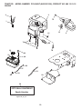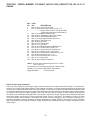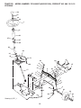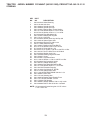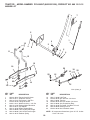
1
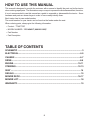
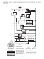
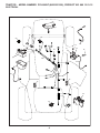
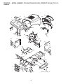
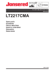
IMPORTANT MANUAL
DO NOT THROW AWAY
5000
REPAIR PARTS MANUAL
MODEL:
PO14542LT
WARNING:
Read this Manual and follow all Warnings
and Safety Instructions. Failure to do so
can result in serious injury.
LAWN TRACTOR
ALWAYS WEAR EYE PROTECTION DURING OPERATION
Visit our website: www.poulan.com
532 44 42-57
05.31.11 BD
Printed in the U.S.A.
HOW TO USE THIS MANUAL
This manual is designed to provide the customer with a means to identify the parts on his/her tractor
when ordering repair parts. The illustrations may or may not represent the actual assemblies; therefore,
it is not recommended to use this manual as a guide to assemble or disassemble the tractor. Some
hardware and parts are drawn larger in order to more readily identify them.
Each tractor has its own model number.
The model number for your tractor can be found on the fender under the seat.
When ordering parts, always give the following information:
• Product - “TRACTOR”
• MODEL NUMBER - “PO14542LT (96012011202)”
• Part Number
• Part Description
TABLE OF CONTENTS
SCHEMATIC ................................................................................................................ 3
ELECTRICAL ............................................................................................................4-5
CHASSIS ..................................................................................................................6-7
DRIVE........................................................................................................................8-9
ENGINE .................................................................................................................10-11
STEERING ............................................................................................................12-13
SEAT .......................................................................................................................... 14
DECALS ..................................................................................................................... 15
MOWER DECK .....................................................................................................16-17
MOWER LIFT ............................................................................................................. 18
WARRANTY............................................................................................................... 19
2
TRACTOR - MODEL NUMBER PO14542LT (96012011202), PRODUCT NO. 960 12 01-12
SCHEMATIC
SCH03
BATTERY
S O LE NO ID
RED
A
RED
STARTER
RED
M
FUSE
AMMETER
(OPTIONAL)
B S M
A1
L A2
WHITE
BLUE
G
CLUTCH / BRAKE
(PEDAL UP)
ATTACHMENT CLUTCH
(CLUTCH OFF)
BLACK
BLACK
SEAT SWITCH
(NOT OCCUPIED)
BLACK
BLACK
GRAY
GRAY
REVERSE SWITCH
NOT IN REVERSE
SHORTING CONNECTOR
BLACK
BLACK
HOUR
METER
BLUE
FUEL
LINE
BLACK
(OPTIONAL)
CHARGING SYSTEM OUTPUT
3 AMP DC @ 3600 RPM
BLUE
RED
SPARK PLUGS
GAP
(2 PLUGS
ON TWIN CYL. ENGINES)
IGNITION
UNIT
BLACK/WHITE
28 VOLTS AC MIN. @ 3600 RPM
(CHARGING SYSTEM DISCONNECTED)
FUEL SHUT-OFF
SOLENOID
LIGHTING SYSTEM OUTPUT
5 AMP AC @ 3600 RPM
LIGHT SWITCH
DIODE
STATOR
ORANGE
14 VOLTS AC MIN. @ 3600 RPM (LIGHTS OFF)
BROWN
IGNITION SWITCH
POSITION
CIRCUIT
OFF
RUN/OVERRIDE
M+G+A1
B+A1
RUN
START
B+A1
B + S + A1
“MAKE”
L+A2
BLACK
NOTE
YOUR TRACTOR IS
EQUIPPED WITH A SPECIAL
ALTERNATOR SYSTEM.
THE LIGHTS ARE NOT
CONNECTED TO THE
BATTERY, BUT HAVE THEIR
OWN ELECTRICAL SOURCE.
BECAUSE OF THIS, THE
BRIGHTNESS OF THE LIGHTS
WILL CHANGE WITH ENGINE
SPEED. AT IDLE THE LIGHTS
WILL DIM. AS THE ENGINE IS
SPEEDED UP, THE LIGHTS
WILL BECOME THEIR BRIGHTEST.
3
HEADLIGHTS
NON-REMOVABLE
CONNECTIONS
REMOVABLE
CONNECTIONS
WIRING INSULATED CLIPS
NOTE: IF WIRING INSULATED CLIPS
WERE REMOVED FOR SERVICING OF
UNIT, THEY SHOULD BE RE-INSTALLED
TO PROPERLY SECURE YOUR WIRING.
TRACTOR - MODEL NUMBER PO14542LT (96012011202), PRODUCT NO. 960 12 01-12
ELECTRICAL
L02
22
79
21
33
90
34
30
27
26
24
43
41
42
2
40
25
28
16
16
94
29
92
93
4
TRACTOR - MODEL NUMBER PO14542LT (96012011202), PRODUCT NO. 960 12 01-12
ELECTRICAL
KEY
NO.
PART
NO.
DESCRIPTION
1
2
8
16
21
22
24
25
26
27
28
29
30
33
34
40
41
42
43
79
90
92
93
94
532 16 34-65
874 76 04-12
532 17 66-89
532 17 61-38
532 17 56-88
532 00 41-52
532 42 12-97
532 42 12-99
532 17 51-58
873 51 04-00
532 42 12-98
532 19 27-49
532 19 33-50
532 41 19-33
532 11 07-12
532 19 74-28
871 11 04-08
532 13 15-63
532 19 25-07
532 17 52-42
532 43 53-95
532 19 66-15
532 19 25-40
532 19 18-34
Battery
Bolt Hex Hd 1/4-20 unc x 3/4
Box Battery
Switch Interlock
Harness Asm Light w/4152j
Bulb Light #1156
Cable Battery
Cable Battery 6 Ga. 11" Red
Fuse 20 AMP
Nut Keps Hex 1/4-20 unc
Cable Ground 6 Ga. 12" Black
Switch Seat
Switch Ign
Key/Chain
Switch Light/Reset
Harness Ign
Bolt Blk Fin Hex 1/4-20
Cover Terminal Red
Solenoid
Socket Asm. Bulb Twistlock
Cover Terminal Battery
Harness Pigtail
Screw Plastite 10-14 x 2.0
Module Reverse ROS
NOTE: All component dimensions given in U.S. inches
1 inch = 25.4 mm.
5
TRACTOR - MODEL NUMBER PO14542LT (96012011202), PRODUCT NO. 960 12 01-12
CHASSIS
29
159
30
212
17
24
18
39
28
24
25
26
5
25
26
5
31
209
209
278
9
11
208
209
208
13
207
64
26
209
35
1
209
33
208
10
142
115
37
145
37
209
35
114
2
209
142
141
205
35
34
38
26
209
38
205
6
Chassis-stlt_Alpha_18
TRACTOR - MODEL NUMBER PO14542LT (96012011202), PRODUCT NO. 960 12 01-12
CHASSIS
KEY
NO.
PART
NO.
DESCRIPTION
1
2
5
9
10
11
13
17
18
24
25
26
28
29
30
31
33
34
35
37
38
39
64
114
115
141
142
145
159
205
207
208
209
212
278
---
532 17 46-19
532 17 65-54
532 15 52-72
532 43 33-53
872 14 06-08
532 17 49-96
532 18 17-19
532 40 61-79
532 18 49-21
874 78 06-16
819 13 13-12
873 80 06-00
532 42 67-41
532 19 54-02
532 19 45-89
532 13 66-19
532 18 25-07
532 18 25-08
872 11 06-06
817 49 05-08
532 17 57-10
532 18 75-68
532 15 47-98
532 15 81-12
817 06 06-20
873 90 06-00
532 17 57-02
532 40 91-67
532 18 56-35
817 49 06-08
817 67 05-08
817 67 06-08
817 00 06-12
532 18 75-69
532 41 63-58
532 00 54-79
532 18 78-01
Chassis
Drawbar, Stretch
Bumper, Hood/Dash
Dash
Bolt, Carriage 3/8-16 x 1
Panel Dash LH
Panel Slkscr Dash RH
Hood
Bumper Hood
Bolt Fin Hex 3/8-16 unc x 1 Gr. 5
Washer 13/32 x 13/16 x 12 Ga.
Nut Lock Hex w/Ins 3/8-16 unc
Grille
Lens Grille Bar
Fender
Bracket Fender Repl 109873X
Footrest Pnt LH
Footrest Pnt RH
Bolt Rdhd Sht Sqnk 3/8-16 x 3/4
Screw Thdrol 5/16-18 x 1/2 TYT
Bracket Asm. Pivot Mower
Bracket Pivot
Dash Lower
Keeper Belt Rear LH
Screw 3/8-16 x 1-1/4
Nut Lock Flg. 3/8-16 unc
Plate Reinforcement
Rod Pivot Chassis/Hood
Cupholder
Screw Thdrol 3/8-16 x 1/2
Screw 5/16-18 x 1/2
Screw Thdrol 3/8-16 x 1/2
Screw Hex Wsh Thdrol 3/8-16
Insert Lens Reflect
Screw #10 x 0.750 BOS Thread
Plug Button Blk 359 Dia Choke
Plug Dome Plastic
NOTE: All component dimensions given in U.S. inches
1 inch = 25.4 mm.
7
TRACTOR - MODEL NUMBER PO14542LT (96012011202), PRODUCT NO. 960 12 01-12
DRIVE
57
120
89
63
69
197
120
81
70
116
66
84
159 158
198 161
65
162
21
85
112
169
13
14
10
80
14
168
82
3
85
55
202
50
18 113
4
8
64
41
83
163
112
56
165
51
166
156
150
38
48
5
11
18
79
16
52
49
32
30
32 170
30
47
6
52
62
6
77
151
51
27
39
6
35
36
120
37
34
25
19
28
24
36
26
2
15
77
96
35
53
26
74
78
29
76
10
27
22
1
26
75
drive-stlt_Peerless_fender_13_r1
8
TRACTOR - MODEL NUMBER PO14542LT (96012011202), PRODUCT NO. 960 12 01-12
DRIVE
KEY
NO.
PART
NO.
1
– – – – – – Transaxle Peerless 206-545C
(165670) (Order parts from
transaxle manufacturer)
532 14 66-82 Spring Return Brake T/a Zinc
532 12 36-66 Pulley Transaxle 18" Tires
812 00 00-28 Ring Retainer # 5100-62
532 12 15-20 Strap Torque 30 Degrees
817 06 05-12 Screw 5/16-18 x 3/4
532 19 27-06 Rod Shift Fender Adjust Lt
876 02 04-16 Pin Cotter 1/8 x 1 Cad
532 10 57-01 Washer Plate Shf 388 Sq Hole
874 55 04-12 Bolt 1/4-28 unf Gr. 8 w/Patch
810 04 04-00 Washer Lock Hvy Helical
874 49 05-40 Bolt Hex FLGHD 5/16-18 Gr. 5
873 80 05-00 Nut Lock Hex w/ins 5/16-18
874 78 06-16 Bolt, Fin Hex 3/8-16 unc x 1 Gr. 5
873 80 06-00 Nut Lock 3/8-16 unc
532 10 69-33 Knob
532 13 08-04 Rod Brake Blk Zinc 26 840
873 35 06-00 Nut Hex Jam 3/8-16 unc
532 10 68-88 Spring Rod Brake 2 00 Zinc
819 13 13-16 Washer 13/32 x 13/16 x 16 Ga.
876 02 04-12 Pin Cotter 1/8 x 3/4 Cad
532 17 57-65 Rod Brake Parking LT/YT
532 07 16-73 Cap Brake Parking
532 16 95-92 Bracket Mtg Transaxle
874 76 05-12 Bolt Hex Hd 5/16-18 unc x 3/4
532 17 55-78 Shaft Asm Pedal Foot
532 12 01-83 Bearing Nylon Blk 629 Id
819 21 16-16 Washer 21/32 x 1 x 16 Ga.
532 12 49-63 Pin Roll 3/16 x 1"
532 17 91-14 Pulley Composite Flat
872 11 06-22 Bolt RDHD 3/8-16 unc x 2-3/4 Gr. 5
532 17 55-56 Keeper Belt Flat Idler
532 12 77-83 Pulley Idler V Groove Plastic
532 15 44-07 Bellcrank Asm
532 12 32-05 Retainer Belt Style Spring
872 11 06-12 Bolt Carr. Sh. 3/8-16 x 1-1/2 Gr. 5
873 68 06-00 Nut Crownlock 3/8-16 unc
873 68 05-00 Nut Crownlock 5/16-18 unc
532 19 96-52 Link Clutch
532 10 57-09 Spring Return Clutch 6 75
817 06 06-20 Screw 3/8-16 x 1-1/4
532 13 82-55 V-Belt Ground Drive
532 12 48-72 Cover Pedal Blk Round
2
3
4
5
6
8
10
11
13
14
15
16
18
19
21
22
24
25
26
27
28
29
30
32
34
35
36
37
38
39
41
47
48
49
50
51
52
53
55
56
57
62
DESCRIPTION
KEY
NO.
PART
NO.
DESCRIPTION
63
64
65
66
69
70
74
75
76
77
78
79
80
81
82
83
84
85
89
96
112
113
116
120
150
151
156
158
159
161
162
163
165
166
168
169
170
197
198
202
532 17 54-10
532 17 39-37
810 04 07-00
532 15 47-78
532 14 24-32
532 13 46-83
532 13 70-57
532 12 17-49
812 00 00-01
532 12 35-83
532 12 17-48
532 12-50-96
532 14 50-90
532 16 55-92
532 16 57-11
819 17 12-16
532 16 62-31
532 15 03-60
532 19 49-71
532 12 47-88
819 09 12-10
532 12 72-85
872 14 06-08
873 90 06-00
532 17 54-56
819 13 32-10
532 16 60-02
532 43 74-58
532 18 39-00
872 14 04-06
873 68 04-00
874 78 04-16
532 43 82-50
817 49 05-10
532 16 54-92
532 16 55-80
532 18 74-14
532 16 96-13
532 16 95-93
872 11 06-14
Engine Pulley
Bolt Hex
Washer Lock Hvy Hlcl Spr 7/16
Keeper Belt Engine Foolproof
Screw Hex wsh HiLo 1/4 x 1/2 unc
Guide Belt Mower Drive RH
Spacer Axle
Washer 25/32 x 1 1/4 x 16 Ga.
E-ring #5133-75
Key Square 2 0 x 1845/ 1865
Washer 25/32 x 1-5/8 x 16 Ga.
Key Woodruff #9 3/16 x 3/4
Arm Shift
Shaft Asm Cross Tapered PMST/20
Spring Torsion T/a
Washer 17/32 x 3/4 x 16 Ga.
Link Transaxle
Nut Lock Center 1/4 - 28 FNTHD
Console Shift STLT
Retainer Spring 1"
Washer 9/32 x 3/4 x 10 Ga.
Strap Torque LT
Bolt Rdhd Sq Neck 3/8-16 x 1
Nut Lock Flg. 3/8-16 unc
Spacer Retainer
Washer 13/32 x 2 x 10
Washer Srrted 5/16ID x 1.125
Bracket Shift Mount
Hub Tapered Flange Shift Lt
Bolt Rdhd Sqnk 1/4-20 x 3/4
Nut Crownlock 1/4-20 unc
Bolt Hex Fin 1/4-20 unc x 1 Gr. 5
Bracket Pivot Lever
Screw 5/16-18 x 5/8
Bolt Shoulder 5/16-18 x .561
Plate Fastening
Keeper Belt Transaxle Gear
Nyliner Snap-In
Washer Nyliner
Bolt RdHd 3/8-16 unc x 1-3/4 Gr. 5
NOTE: All component dimensions given in U.S. inches
1 inch = 25.4 mm
9
TRACTOR - MODEL NUMBER PO14542LT (96012011202), PRODUCT NO. 960 12 01-12
ENGINE
3
2
72
1
13
81
78
122
78
32
44
31
46
33
37
45
111
33
23
40
29
OPTIONAL EQUIPMENT
Spark Arrester
engine-stlt_bs_24
10
4
TRACTOR - MODEL NUMBER PO14542LT (96012011202), PRODUCT NO. 960 12 01-12
ENGINE
KEY
NO.
PART
NO.
1
2
3
532 17 05-51 Control Th/ch Flag
817 72 04-08 Screw Hex Thd Cut 1/4-20 x 1/2
– – – – – – Engine, B&S 31A507-1405-B1 (431930)
(Order parts from engine manufacturer)
532 13 73-52 Muffler Exhaust B&S
532 16 52-91 Gasket Eng 1 313 Id Tin Plated
532 16 98-37 Shield BRN/DBR Guard
532 13 71-80 Kit Spark Arrestor (Flat Scrn)
532 43 30-03 Tank Fuel Front
532 43 85-96 Cap Fuel
532 12 34-87 Clamp Hose
532 40 11-37 Line Fuel
532 12 40-28 Bushing Snap Nyl Blk Fuel Line
817 67 04-12 Screw Thdrol 1/4-20 x 3/4
817 00 06-12 Screw Hex Wsh Thdrol 3/8-16
819 09 14-16 Washer 9/32 x 7/8 x 16 Ga.
532 19 23-34 Screw Socket Head 5/16-18 x 3/4
817 06 06-20 Screw 3/8-16 x 1-1/4
873 51 04-00 Nut Keps Hex 1/4-20 unc
532 41 41-19 Purge Line
532 42 19-22 Extension Drain Oil
4
13
23
29
31
32
33
37
40
44
45
46
72
78
81
111
122
DESCRIPTION
NOTE: All component dimensions given in U.S. inches
1 inch = 25.4 mm
For engine service and replacement parts, call the toll free
number for your engine manufacturer listed below:
Briggs & Stratton
1-800-233-3723
Engine Power Rating Information
The gross power rating for individual gas engine models is labeled in accordance with SAE (Society of Automotive Engineers) code J1940 (Small Engine Power & Torque Rating Procedure), and rating performance has been obtained and
corrected in accordance with SAE J1995 (Revision 2002-05). Torque values are derived at 3060 RPM; horsepower values
are derived at 3600 RPM. Actual gross engine power will be lower and is affected by, among other things, ambient operating conditions and engine-to-engine variability. Given both the wide array of products on which engines are placed and
the variety of environmental issues applicable to operating the equipment, the gas engine will not develop the rated gross
power when used in a given piece of power equipment (actual “on-site” or net power). This difference is due to a variety
of factors including, but not limited to, accessories (air cleaner, exhaust, charging, cooling, carburetor, fuel pump, etc.),
application limitations, ambient operating conditions (temperature, humidity, altitude), and engine-to-engine variability.
Due to manufacturing and capacity limitations, Briggs & Stratton may substitute an engine of higher rated power for this
Series engine.
11
TRACTOR - MODEL NUMBER PO14542LT (96012011202), PRODUCT NO. 960 12 01-12
STEERING
38
97
34
39
1
41
42
37
37
36
44
88
91
43
71
67
68
46
8
29
67
6
13
9
2
17
65
46
7
82
9
5
8
9
6
7
9
40
68
32
5
29
26
3
43
11
15
29
43
28
10
4
95
8
Steering-lt_OPP_1
30
12
TRACTOR - MODEL NUMBER PO14542LT (96012011202), PRODUCT NO. 960 12 01-12
STEERING
KEY
NO.
PART
NO.
DESCRIPTION
1
2
3
4
5
6
7
8
9
10
11
13
15
17
26
28
29
30
32
34
36
37
38
39
40
41
42
43
44
46
65
67
68
71
82
88
91
95
97
532 42 45-43
532 41 81-68
532 16 98-40
532 16 98-39
532 12 49-31
532 12 17-48
819 27 20-16
812 00 00-29
532 12 49-37
532 17 51-21
810 04 06-00
532 13 65-18
873 90 06-00
532 41 13-86
532 12 68-47
819 13 14-16
817 00 06-12
876 02 04-12
532 19 27-57
810 04 05-00
532 15 50-99
532 15 29-27
532 42 46-91
819 11 38-12
873 54 06-00
532 18 67-37
532 16 96-33
532 12 17-49
532 19 07-52
532 12 12-32
532 41 47-36
872 11 06-18
532 16 98-27
532 17 51-46
532 19 99-78
532 17 51-18
532 17 55-53
532 18 89-67
532 42 89-82
Wheel Steering
Axle Asm
Spindle Asm LH
Spindle Asm RH
Bearing Race Thrust Harden
Washer 25/32 x 1-5/8 x 16 Ga.
Washer 27/32 x 1-1/4 x 16 Ga.
Ring Klip #t5304-75
Bearing Col Strg Blk
Link Drag
Washer Lock Hvy Hlcl Spr 3/8
Spacer Brace Axle
Nut lock Flg. 3/8-16 unc
Shaft Asm Strg
Bushing Link Drag Blk LR
Washer 13/32 x 7/8 x 16 Ga.
Screw 3/8-16 x 3/4
Pin Cotter 11/32 ID x 2 3/8 OD x 12 Ga.
Rod Tie Wire Form 19 75 Mech
Washer Lock 5/16
Bushing Strg 5/8 Id Dash
Screw
Cap Wheel Steer
Washer 11/32 x 2 3/8 OD x 12 Ga.
Nut Crownlock 3/8-24
Adaptor Wheel Strg
Boot Dash Mtl Steering Blk
Washer 25/32 x 1 1/4 x 16 Ga.
Extension Steering
Cap Spindle Fr Top Blk
Spacer Brace Axle
Bolt RDHD SQNK 3/8-16 x 2-1/4
Brace Axle
Steering Asm.
Bracket Susp Chassis Front
Bolt Shoulder 7/16-20
Clip Steering
Washer Harden .793 x 1.637 x 060
Bolt Fin Hex 5/16-18 x 4 w/Patch
NOTE: All component dimensions given in U.S. inches
1 inch = 25.4 mm.
13
TRACTOR - MODEL NUMBER PO14542LT (96012011202), PRODUCT NO. 960 12 01-12
SEAT
1
8
8
9
14
9
7
7
10
5
6
22
21
2
24
5
16
25
15
11
4
13
17
3
12
seat-stlt_knob_1
KEY
NO.
1
2
3
4
5
6
7
8
9
10
11
12
PART
NO.
532 40 10-42
532 14 05-51
871 11 06-16
819 13 16-10
532 14 50-06
873 80 06-00
532 12 41-81
817 00 06-16
819 13 16-14
532 19 55-30
532 16 63-69
532 17 46-48
KEY
NO.
13
14
15
16
17
21
22
24
25
DESCRIPTION
Seat
Bracket Seat Pivot
Bolt Hex 3/8 - 16 x 1
Washer 13/32 x 1 x10 Ga.
Clip Push-In Hinged
Nut Lock Hex w/Ins 3/8 - 16
Spring Seat Cprsn 2 250 Blk Zi
Screw 3/8-16 x 1.5
Washer 13/32 x 1 x 14 Ga.
Pan Pnt Seat
Knob Seat
Bracket Pnt Mounting Switch
PART
NO.
532 12 12-48
872 05 04-12
532 13 43-00
532 12 12-50
532 12 39-76
532 17 18-52
873 80 05-00
819 17 19-12
532 12 70-18
DESCRIPTION
Bushing Snap Blk Nyl
Bolt Rdhd Sht Nk 1/4 - 20 x 1 -1/2
Spacer Split .28 x .96
Spring Cprsn
Nut Lock 1/4 Lge Flg
Bolt Shoulder 5/16-18 unc-2A
Nut Lock Hex w/Ins 5/16 - 18
Washer 17/32 x 1-3/16 x 12 Ga.
Bolt Shoulder 5/16-18 x .62
NOTE: All component dimensions given in U.S. inches
1 inch = 25.4 mm.
14
TRACTOR - MODEL NUMBER PO14542LT (96012011202), PRODUCT NO. 960 12 01-12
DECALS
7
2
12
6
12
15
9
4
11
5
11
5
3
10
KEY
NO.
PART
NO.
DESCRIPTION
KEY
NO.
PART
NO.
DESCRIPTION
2
3
4
5
6
7
9
10
532 19 46-91
532 43 10-89
532 17 05-63
532 43 19-85
532 41 16-57
532 43 19-82
532 43 19-86
532 16 03-96
Decal, Replacement
Decal, Engine HP
Decal, Warning
Decal, Fender
Decal, Fender Warning (E&F)
Decal, Ins Str Wh
Decal, Fender
Decal, V-Belt Sch.
11
12
15
------
532 43 84-87
532 43 19-83
532 14 50-05
532 18 10-90
532 18 10-91
532 13 83-11
532 43 85-11
532 44 42-57
Decal, Lower Dash
Decal, Hood RH/LH
Decal, Caution, Battery
Pad Footrest RH
Pad Footrest LH
Decal, Handle Lft Height Adj.
Manual, Operator's, English/Spanish
Manual, Parts, English/Spanish
KEY
NO.
PART
NO.
DESCRIPTION
1
2
3
4
5
6
7
8
9
10
11
--
532 05 91-92
532 06 51-39
532 10 62-22
532 05 99-04
532 43 87-27
532 12 49-57
532 12 49-59
532 43 87-26
532 42 05-31
532 12 49-26
532 19 32-68
532 14 43-34
Cap, Tire Valve
Stem, Valve
Tire, Front
Tube, Front (Service item only)
Rim Assembly, 6" Front
Fitting, Grease (Front wheel only)
Bearing, Flange (Front wheel only)
Rim Assembly, 8" Rear
Tire, Rear
Tube, Rear (Service item only)
Cap, Hub Axle
Sealant, Tire (10 oz. Tube)
WHEELS & TIRES
1
2
5,8
4,10
7
3,9
6
11
NOTE: All component dimensions given in U.S. inches
1 inch = 25.4 mm
wheel_1
15
TRACTOR - MODEL NUMBER PO14542LT (96012011202), PRODUCT NO. 960 12 01-12
MOWER DECK
67
40
158
36
40
185
143
144
159
42
_c
lu
tc
h_
m
od
_7
152
45
150
68
40
46
145
44
184
59
56
53
52 55
54
48
142
147
148
146
33
32
31
30
1
21
21
34
21
147
23
2
24
25
21
26
142
29
2 15
14
3
4
5
20
149
18
13
6
19
18
11
21
8
?DECK?STD?
16
28
27
TRACTOR - MODEL NUMBER PO14542LT (96012011202), PRODUCT NO. 960 12 01-12
MOWER DECK
KEY
NO.
PART
NO.
1
2
3
4
5
6
8
532 16 58-92
872 14 05-06
532 13 80-17
532 16 54-60
532 12 46-70
532 17 80-24
532 19 30-03
11
532 13 89-71
13
14
15
18
19
20
21
23
24
25
26
27
28
29
30
31
32
33
34
36
40
44
45
46
48
532 19 28-72
532 18 72-81
532 11 04-85
872 14 05-05
532 13 28-27
532 15 97-70
873 68 05-00
532 17 75-63
532 10 53-04
532 12 37-13
532 11 04-52
532 17 18-59
819 11 10-16
532 13 14-91
532 17 39-84
532 18 76-90
532 15 35-35
532 40 02-34
872 11 06-12
532 13 14-94
873 90 06-00
532 14 00-88
532 12 47-88
532 13 77-29
532 13 39-44
KEY
NO.
DESCRIPTION
52
53
54
55
56
59
67
68
142
143
144
145
146
147
148
149
150
152
158
159
184
185
208
--
Mower Deck Assembly, 42"
Bolt
Bracket Asm Fr. Sway Bar 3/42
Bracket Asm Deck 42" Sway Bar
Retainer Spring
Bar Sway Deck
Bolt/Washer Asm. 7/16-20 unf
(The following Blades are available)
Blade Mower 42” Hi-Lift (for bagging and discharging)
Shaft Asm. Mandrel
Housing Mandrel
Bearing, Ball, Mandrel
Bolt, Carriage 5/16-18 x 5/8
Bolt, Shoulder
Baffle, Vortex
Nut
Bracket, Deflector Mower 42"
Cap, Sleeve 80 x 112 Blk Mower
Spring, Torsion, Deflector 2 52
Nut, Push Phos & Oil
Shield, Deflector 42" Blk
Washer 11/32 x 5/8 x 16 Ga.
Rod, Hinge 42" 6 75 w/G
Screw Thdrol
Washer, Spacer Mower Vented
Pulley, Mandrel
Nut, Toplock
Bolt Carr SH 3/8-16 x 1-1/2 Gr.5
Pulley, Idler, Flat
Nut Lock 3/8-16
Guard, Mandrel, LH
Retainer
Screw, Thdrol 1/4-20 x 5/8 T
Washer, Hardened
--
PART
NO.
DESCRIPTION
532 13 98-88
532 18 49-07
532 17 85-15
532 15 50-46
532 16 57-23
532 14 10-43
532 10 69-32
532 14 49-59
532 19 57-84
532 15 71-09
532 15 86-34
532 16 58-88
532 17 19-77
532 13 13-35
532 16 90-22
532 16 58-98
819 09 12-10
532 16 96-76
817 72 04-08
872 14 06-14
819 13 14-10
532 18 82-34
817 67 06-08
532 19 28-70
Bolt, Shoulder 5/16-18 unc
Arm Assembly, Pad, Brake
Washer, Hardened
Arm, Idler
Spacer, Retainer
Guard TUV Idler
Knob Round
V-Belt, 42" Mower
Anchor Spring Brake Mower
Bracket Arm Idler 42"
Keeper Belt 42" Clutch Cable
Pulley Idler Flat
Bolt Carriage Idler
Spring Extension
Spring Return Idler
Retainer Spring Yellow
Washer 9/32 x 3/4 x 10 Ga.
Clutch Cable 42"
Screw Hex Thd Cut 1/4-20 x 1/2
Bolt Rdhd Sqn 3/8-16 unc x 1-3/4
Washer 13/32 x 7/8 x 10 Ga.
Head Asm Cable Clutch
Screw 3/8-16 x 1/2
Mandrel Assembly (Includes housing, shaft assembly, and bearing
only - pulley/nut/washer and blade
bolt/washers not included)
532 41 80-31 Replacement Mower, Complete
NOTE: All component dimensions given in U.S. inches
1 inch = 25.4 mm
17
TRACTOR - MODEL NUMBER PO14542LT (96012011202), PRODUCT NO. 960 12 01-12
MOWER LIFT
7
8
5
1
3
13
2
4
6
6
11
5
4
12
13
19
20
20
31
32
13
15
DESCRIPTION
1
2
3
4
5
6
7
8
11
12
13
532 40 49-81
532 15 94-71
532 10 57-67
812 00 00-02
819 21 16-21
532 12 01-83
532 12 56-31
532 12 45-26
532 13 98-65
532 13 98-66
532 12 46-70
Plunger Asm Lift Lever
Shaft Asm Lift RH
Pin Groove 1 500 Zinc
E Ring #5133-62
Washer 21/32 x 1 x 21 Ga.
Bearing Nylon Blk 629 Id
Grip Handle
Button Plunger Black
Link Lift LH Fixed Length
Link Lift RH Fixed Length
Retainer Spring
20
15
31
32
PART
NO.
16 17
20
19
KEY
NO.
18
lift-rh.1piece_3
18
KEY
NO.
PART
NO.
DESCRIPTION
15
16
17
18
19
20
31
32
532 17 32-88
873 35 08-00
532 17 56-89
873 80 08-00
532 13 98-68
532 19 42-09
532 16 98-65
873 54 06-00
Link Front
Nut Jam Hex 1/2-13 unc
Trunnion
Nut Lock w/Wsh 1/2-13 unc
Arm Suspension Rear
Pin Cotter 7/16 Bow Tie Lock
Bearing Pvt Lift
Nut Crownlock 3/8-24
NOTE: All component dimensions given in U.S. inches
1 inch = 25.4 mm.
LIMITED WARRANTY
The Manufacturer warrants to the original consumer purchaser that this product as manufactured is free from defects in materials and workmanship. For a period of two (2) years from date of purchase by the original consumer purchaser, we will repair
or replace, at our option, without charge for parts or labor incurred in replacing parts, any part which we find to be defective
due to materials or workmanship. This Warranty is subject to the following limitations and exclusions.
1.
This warranty does not apply to the engine, transaxle/transmission components, battery (except as noted below) or components parts thereof. Please refer to the applicable manufacturer's warranty on these items.
2.
Transportation charges for the movement of any power equipment unit or attachment are the responsibility of the purchaser. Transportation charges for any parts submitted for replacement under this warranty must be paid by the purchaser unless such return is requested by the manufacturer.
3.
Battery Warranty: On products equipped with a Battery, we will replace, without charge to you, any battery which we find
to be defective in manufacture, during the first ninety (90) days of ownership. After ninety (90) days, we will exchange the
Battery, charging you 1/12 of the price of a new Battery for each full month from the date of the original sale. Battery must
be maintained in accordance with the instructions furnished.
4.
The Warranty period for any products used for rental or commercial purposes is limited to 90 days from the date of original purchase.
5.
This Warranty applies only to products which have been properly assembled, adjusted, operated, and maintained in accordance with the instructions furnished. This Warranty does not apply to any product which has been subjected to alteration, misuse, abuse, improper assembly or installation, delivery damage, or to normal wear of the product.
6.
Exclusions: Excluded from this Warranty are belts, blades, blade adapters, normal wear, normal adjustments, standard
hardware and normal maintenance.
7.
In the event you have a claim under this Warranty, you must return the product to an authorized service dealer.
Should you have any unanswered questions concerning this Warranty, please contact:
In Canada contact:
HOP
Outdoor Products Customer Service Dept.
9335 Harris Corners Parkway
Charlotte, NC 28269 USA
HOP
5855 Terry Fox Way
Mississauga, Ontario
L5V 3E4
giving the model number, serial number and date of purchase of your product and the name and address of the authorized
dealer from whom it was purchased.
THIS WARRANTY DOES NOT APPLY TO INCIDENTAL OR CONSEQUENTIAL DAMAGES AND ANY IMPLIED WARRANTIES ARE LIMITED TO THE SAME TIME PERIODS STATED HEREIN FOR OUR EXPRESSED WARRANTIES. Some areas
do not allow the limitation of consequential damages or limitations of how long an implied Warranty may last, so the above
limitations or exclusions may not apply to you. This Warranty gives you specific legal rights, and you may have other rights
which vary from locale to locale.
This is a limited Warranty within the meaning of that term as defined in the Magnuson-Moss Act of 1975.
19
PARTS AND SERVICE
This product has been expertly engineered and carefully manufactured to rigid quality standards. As with all mechanical
products, some adjustments or part replacement may be necessary during the life of your unit.
For Parts and service, contact our authorized distributor: call 1-800-849-1297
•
For replacement parts, have available the following information:
a. Model Number/Manufacturer's I.D. Number
b. Description of part.
For Technical Assistance: call 1-800-829-5886
For a Parts Manual, go to our website: www.poulan.com
NOTE:
HOP provides parts and service through its authorized distributors and dealers; therefore, all
requests for parts and service should be directed to your local dealer(s). The philosophy of HOP
is to continually improve all of its products. If the operating characteristics or the appearance
of your product differs from those described in this Manual, please contact your local dealer
for updated information and assistance.
20