1
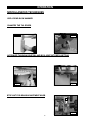
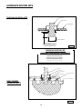
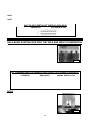
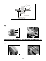
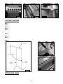
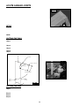
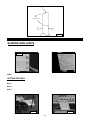
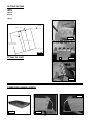
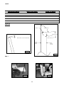
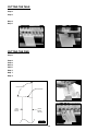
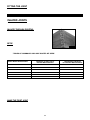
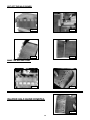
12" (305 mm)
DOVETAIL JIG
Gabarit de queues d'aronde
de 305 mm (12 po)
Guí de 305 mm (12 pulg)
para cola de milano
Advanced Instruction Manual
www.deltaportercable.com/jigs
4210
4212
4216
TABLE OF CONTENTS
SAFETY GUIDELINES
3
IMPORTANT SAFETY INSTRUCTIONS
3
ADDITIONAL SPECIFIC SAFETY RULES
4
BACKGROUND INFORMATION
4
OPERATION
5
MISCELLANEOUS TECHNIQUES
5
THROUGH-DOVETAILS WITH CLAMPING BOARDS
6
THROUGH-DOVETAILS WITH UNLIMITED BOARD WIDTH
8
ALTERNATIVE METHOD - THROUGH-DOVETAILS WITH UNLIMITED BOARD WIDTH
10
HALF-BLIND DOVETAILS WITH CLAMPING BOARDS
11
USING A ROUTER TABLE
13
ALTERNATE ROUTER BITS
14
HALF-BLIND DOVETAIL TAILBOARDS THICKER THAN 7/8"
17
MITERED THROUGH-DOVETAILS
18
THROUGH-DOVETAIL, SKIPPED PIN METHOD
19
HALF-BLIND DOVETAIL, SKIPPED PIN METHOD
20
SAW KERF ALLOWANCE METHOD
22
MULTIPLE SPACER METHOD
24
END-TO-END JOINTS
24
DRAWERS WITH SLIDING DOVETAILS
25
WOODEN HINGES
26
ANGLED JOINTS
29
ACUTE ANGLED JOINTS
32
SLANTED SIDE JOINTS
33
COMPOUND ANGLED JOINTS
34
INLAYED THROUGH-DOVETAILS
37
INLAYED HALF-BLIND DOVETAIL JOINTS
38
INLAYED BOX JOINTS
40
TABLES OF COMMONLY AVAILABLE ROUTER BIT SIZES
41
TROUBLESHOOTING
42
MAINTENANCE
42
SERVICE
42
ACCESSORIES
42
WARRANTY
43
Back Cover
SERVICE CENTER LOCATIONS
2
SAFETY GUIDELINES - DEFINITIONS
This manual contains information that is important for you to know and understand. This information relates to protecting YOUR SAFETY and PREVENTING EQUIPMENT PROBLEMS. To help you recognize this information, we use
the symbols to the left. Please read the manual and pay attention to these sections.
Indicates an imminently hazardous situation which, if not avoided, will result in death or serious injury.
Indicates a potentially hazardous situation which, if not avoided, could result in death or serious injury.
Indicates a potentially hazardous situation which, if not avoided, may result in minor or moderate injury.
Used without the safety alert symbol indicates potentially hazardous situation which, if not avoided, may
result in property damage.
IMPORTANT SAFETY INSTRUCTIONS
Read and understand all instructions. Failure to follow all instructions listed below, may
result in electric shock, fire and/or serious personal injury.
SAVE THESE INSTRUCTIONS.
There are certain applications for which this tool was designed. Porter-Cable strongly recommends that this
tool NOT be modified and/or used for any application other than for which it was designed. If you have any questions relative to
its application DO NOT use the tool until you have written Porter-Cable and we have advised you.
Technical Service Manager
Porter-Cable Corporation
4825 Highway 45 North
Jackson, TN 38305
1.
2.
3.
4.
5.
6.
7.
8.
9.
10.
11.
12.
13.
14.
15.
KEEP WORK AREA CLEAN. Cluttered areas and benches invite injuries.
AVOID DANGEROUS ENVIRONMENT. Don’t expose power tools to rain. Don’t use power tools in damp or wet
locations. Keep area well lit. Avoid chemical or corrosive environment. Do not use tool in presence of flammable
liquids or gases.
GUARD AGAINST ELECTRIC SHOCK. Prevent body contact with grounded surfaces. For example: pipes,
radiators, ranges, refrigerator enclosures.
KEEP CHILDREN AWAY. Do not let visitors contact tool or extension cord. All visitors should be kept away from
work area.
STORE IDLE TOOLS. When not in use, tools should be stored in dry, and high or locked-up place – out of reach
of children.
DON’T FORCE TOOL. It will do the job better and safer at the rate for which it was intended.
USE RIGHT TOOL. Don’t force small tool or attachment to do the job of a heavy duty tool. Don’t use tool for
purpose not intended – for example – do not use a circular saw for cutting tree limbs or logs.
DRESS PROPERLY. Do not wear loose clothing or jewelry. Loose clothing, draw strings and jewelry can be
caught in moving parts. Rubber gloves and non-skid footwear are recommended when working outdoors. Wear
protective hair covering to contain long hair.
USE ANSI Z87.1 SAFETY GLASSES. Wear safety glasses or goggles while operating power tools. Also face or
dust mask if operation creates dust. All persons in the area where power tools are being operated should also
wear safety glasses and face or dust mask.
DON’T ABUSE CORD. Never carry tool by cord or yank it to disconnect from receptacle. Keep cord from heat,
oil, and sharp edges. Have damaged or worn power cord and strain reliever replaced immediately. DO NOT
ATTEMPT TO REPAIR POWER CORD.
SECURE WORK. Use clamps or a vise to hold work. It’s safer than using your hand and it frees both hands to
operate tool.
DON’T OVERREACH. Keep proper footing and balance at all times.
MAINTAIN TOOLS WITH CARE. Keep tools sharp and clean for better and safer performance. Follow
instructions for lubricating and changing accessories. Inspect tool cords periodically and if damaged, have
repaired by authorized service facility. Inspect extension cords periodically and replace if damaged. Have all
worn, broken or lost parts replaced immediately. Keep handles dry, clean and free from oil and grease.
DISCONNECT TOOLS when not in use, before servicing, and when changing accessories such as blades, bits, cutters, etc.
REMOVE ADJUSTING KEYS AND WRENCHES. Form habit of checking to see that keys and adjusting
wrenches are removed from the tool before turning it on.
3
16. AVOID UNINTENTIONAL STARTING. Do not carry a plugged-in tool with finger on switch. Be sure switch is off
when plugging in. Keep hands, body and clothing clear of blades, bits, cutters, etc. when plugging in the tool.
17. OUTDOOR USE EXTENSION CORDS. When tool is used outdoors, use only extension cords marked “Suitable
for use with outdoor appliances – store indoors when not in use.” If an extension cord is to be used outdoors it
must be marked with the suffix W-A or w following the cord type designation.
18. STAY ALERT. Watch what you are doing. Use common sense. Do not operate tool when you are tired or while
under the influence of medication, alcohol or drugs.
19. CHECK DAMAGED PARTS. Before further use of the tool, a guard or other part that is damaged should be
carefully checked to determine that it will operate properly and perform its intended function. Check for alignment
of moving parts, binding of moving parts, breakage of parts, mounting, and any other conditions that may affect
its operation. A guard or other part that is damaged should be properly repaired or replaced by an authorized
service center unless otherwise indicated elsewhere in this instruction manual. Have defective switches replaced
by authorized service center. Do not use tool if switch does not turn it on and off.
20. WEAR ANSI S3.19 EAR PROTECTION to safeguard against possible hearing loss.
ADDITIONAL SAFETY RULES
FAILURE TO FOLLOW THESE RULES MAY RESULT IN SERIOUS PERSONAL INJURY.
1.
2.
3.
4.
5.
6.
7.
READ AND FOLLOW ALL SAFETY INSTRUCTIONS in the instruction manual supplied with your router.
SECURE WORK. Be sure Dovetail Fixture/Jig and work is anchored securely to prevent movement.
BE SURE CORD SET IS FREE and will not hang up during routing operations.
KEEP HANDS CLEAR of cutter when motor is running to prevent personal injury.
MAINTAIN FIRM GRIP on router when starting motor to resist starting torque.
STAY ALERT and keep cutter free, clear of all foreign objects while motor is running.
BE SURE MOTOR HAS COMPLETELY STOPPED before removing router from Dovetail Fixture/Jig and setting
Dovetail Fixture/Jig down between operations.
8. NEVER REMOVE ROUTER MOTOR from router base while template guide and dovetail bit are installed. dovetail
bit may not fit through hole in template guide.
9. TIGHTEN TEMPLATE GUIDE LOCKNUT SECURELY.
10. SOME WOOD CONTAINS PRESERVATIVES WHICH CAN BE TOXIC. Take extra care to prevent inhalation and
skin contact when working with these materials. Request, and follow, any safety information available from your
material supplier.
CALIFORNIA PROPOSITION 65
Some dust created by power sanding, sawing, grinding, drilling, and other construction
activities contains chemicals known to cause cancer, birth defects or other reproductive harm.
Some examples of these chemicals are:
• lead from lead-based paints,
• crystalline silica from bricks and cement and other masonry products, and
• arsenic and chromium from chemically-treated lumber.
Your risk from these exposures varies, depending on how often you do this type of work. To reduce your
exposure to these chemicals: work in a well ventilated area, and work with approved safety equipment, always
wear NIOSH/OSHA approved, properly fitting face mask or respirator when using such tools.
REPLACEMENT PARTS
When servicing use only identical replacement parts.
BACKGROUND INFORMATION
The details for basic joints are found in the instruction manual for the 4210, 4212 or 4216 Dovetail Jig, along
with information regarding the use of various router bits and/or template guides, and will not be repeated in this
supplemental manual. The purpose of this document is to provide you with an advanced knowledge of the jig and
to promote that knowledge, along with your creativity, to produce beautiful woodworking projects that can stand
the test of time.
4
OPERATION
MISCELLANEOUS TECHNIQUES
Using these techniques can simplify your dovetailing projects.
USE A DEAD-BLOW HAMMER
Use a plastic dead-blow hammer to join your workpieces together to help prevent the marring of wood (Fig. 1A).
CHAMFER THE TAIL EDGES
Chamfering the inner tail edges can make the joints go together easier and may prevent damage to the pins (Fig.
1B). Make the chamfers with a file or a chisel. Since the chamfers are located on the inside of the joint, they will
be invisible.
Fig. 1A
Fig. 1B
ALTERNATE THROUGH DOVETAIL AND BOX JOINT BIT DEPTH SETTING
This method of setting your router bit depth on through dovetails or box joints is very accurate for creating pins or
tails that are flush, and is especially good for inlay work. Use a board that is the same thickness as your workpiece
to be joined and draw a line.
Fig. 2B
Fig. 2A
Set the router on the template and lower the router bit until it reaches the line. Make sure that the scrap material
used in the horizontal position to support the template is at least as thick as the router bit depth-of-cut.
STOP NUT FOR BRASS ADJUSTMENT KNOB
A
If using the same setup repeatedly, you can use a 3/8"-16 nut (A)
Fig. 3A (not supplied) to keep the brass adjustment knobs from
moving.
Fig. 3A
5
TEMPLATES MOUNTED TO CLAMPING BOARDS
You can mount the jig templates to clamping boards and take the templates to the workpiece to make the joint. The
benefits of this operation are:
1. You can maneuver a mounted template onto a large workpiece easier than clamping a large workpiece to the jig.
This process allows you to join boards wider than 12" by routing a part of the joint, sliding the mounted template
just past the original cut, and routing the remainder of the joint.
Fig. 4B
Fig. 4A
Fig. 4C
2. By using the clamping boards, you can rout boards that
are too short to clamp in the jig base, allowing you to
dovetail small decorative boxes.
3. You can make half-blind joints in thicker wood than the jig can handle.
4. You can make steeply-angled joints with the clamping boards.
5. You can make joints using a router table by inverting the mounted templates.
THROUGH-DOVETAILS WITH CLAMPING BOARDS
You can use both the normal through-dovetail template (included with the 4212 Jig and the 4213 Accessory Kit),
and the miniature through-dovetail template (included with the 4215 Accessory Kit) with a clamping board.
NOTE: You can modify these clamping board methods to make box joints.
SETUP
Step 1 - Make a clamping board 2" x 3" x 19". Make
sure that all four sides are square (You may need
to glue thinner sections of wood together and
plane them to make the 2" board).
Step 2 - Drill the pilot holes for #10 screws on the face of
the board as indicated in the drawing (Fig. 6A).
Step 3 - Remove the brackets from the template (Fig.
6B).
Step 4 - Align the lines of the template with the edges
of the clamping board. You should be able to
see the pilot holes in the elongated slot of the
template Fig. 6C).
Step 5 - Drive two #10 wood screws through the
elongated slots of the template into the clamping
board (Fig. 6D).
6
Fig. 6A
DRILL PILOT HOLES
FOR #10 WOOD SCREWS
1"
13 "
3"
19 "
WOOD GRAIN
3"
2"
Fig. 6B
Fig. 6C
Fig. 6D
CUTTING THE TAILS
Step 1 - Clamp the tail board with the outside surface facing away from the clamping board (Fig. 7A). Align
the tail board, using the instructions in your basic manual in the section “OPERATION”. Look under
“POSITIONING THE WOOD”, STEP 4.
Step 2 - This step is optional. Clamp stop blocks to the clamping board for rapid setups of repeated cuts.
Step 3 - Use a small square and a pencil to draw a line along the bottom of the clamping board (Fig. 7B). Align the
line with an edge of the tail board. (This line will be used to set up the pin board).
Step 4 - Use the width of the pinboard to mark the depth of the router bit on the tailboard (Fig. 7C).
DISCONNECT THE TOOL FROM THE POWER SOURCE.
Step 5 - Set the router bit depth, using the pencil mark from STEP 4.
Step 6 - Connect your router to the power source and cut the tails (Fig. 7D).
Fig. 7B
Fig. 7A
7
Fig. 8A
Fig. 8B
Fig. 8C
Fig. 8D
FITTING THE JOINT
Step 1 - Orient the template so that the “PINS” side is
facing you (Fig. 9A).
Step 2 - Loosen the two #10 screws.
Step 3 - If the joint is too loose, move the template
toward you slightly.
Step 4 - If the joint is too tight, move the template away
from you slightly.
Step 5- Tighten the screws loosened in STEP 2.
Step 6 - Cut the pin board again and check for fit.
Fig. 9A
THROUGH-DOVETAILS WITH UNLIMITED BOARD WIDTH
You can cut dovetails in boards wider than the templates mounted on clamping boards by cutting the first part of
the joint, sliding the template down the workpiece, and cutting the rest of the joint.
NOTE: Become familiar with the procedure for cutting through-dovetails with a template on a clamping board before
attempting working with unlimited board width.
SETUP
Remove the half-blind depth bracket. Other than that, the setup is identical to the previous setup.
8
CUTTING THE TAILS
Step 1 - Clamp the tail board with the outside surface facing away from the clamping board (Fig. 10A).
Step 2 - If the board is a width in 1" increments, (12", 13", etc.), center the edge of the board exactly between the
two fingers of the template farthest to the left (Fig. 10B).
Step 3 - If the board is not in 1" increments, take the fraction of an inch that is greater than 1" and divide it by two.
Then move the tailboard to the left of the center of the fingers by that amount (Fig. 10C). EXAMPLE: IF
the board width is 16-1/2", take the 1/2", divide it by two. You would then move the tail board to the left
of the center of the fingers by 1/4" and clamp it in place.
Step 4 - Use a piece of wood the same thickness as the pin board to mark the router bit depth.
DISCONNECT THE TOOL FROM THE POWER SOURCE.
Set
the
router bit depth, using the pencil mark from STEP 4.
Step 5 Step 6 - Connect your router to the power source and cut the pins as far as the template will allow.
Fig. 10B
Fig.10A
Fig. 10C
Step 7 - Unclamp the template, slide it down, and center the last cut
between the two straight fingers and reclamp (Fig. 10D).
Step 8 - Repeat STEPS 6 and 7 until the pins are cut across the entire
board.
CUTTING THE PINS
Fig. 10D
Step 1 - Clamp the pin board with the outside surface facing away from the clamping board.
Step 2 - If the board is a width in 1" increments, (12", 13", etc.), center the edge of the board exactly in line with the
finger of the template farthest to the left (Fig. 11A).
Step 3 - If the board is not in 1" increments, take the fraction of an inch that is greater than 1" and divide it by two.
Then move the pin board to the left of center of the fingers by that amount. EXAMPLE: IF the board width
is 16-1/2", take the 1/2", divide it by two. You would then move the tail board to the left of the leftmost
finger by 1/4" and clamp it in place (Fig. 11B).
Step 4 - Use a piece of wood the same thickness as the pin board to mark the router bit depth.
DISCONNECT THE TOOL FROM THE POWER SOURCE.
Step 5 - Set the router bit depth, using the pencil mark from STEP 4.
Step 6 - Connect your router to the power source and cut the pins as far as the template will allow.
Fig. 11A
Fig. 11B
9
Step 7 - Unclamp the template, slide it down, and center the last cut between the two angled fingers and reclamp
(Fig. 11D).
Step 8 - Repeat STEPS 6 and 7 until the pins are cut across the entire board.
Step 9 - Remove the pin board and check the fit with the tailboard.
FITTING THE JOINT
Fitting the joint is identical to the previous section (Fig. 12A).
Fig. 11D
Fig. 12A
ALTERNATE METHOD
THROUGH-DOVETAILS WITH UNLIMITED BOARD WIDTH
This alternate method may be more accurate for correctly cutting the tail and pin boards.
Step 1 - Clamp the tail and pin boards together with a 2" wide block (Fig. 13A).
Step 2 - Use a square to align an edge of the tail and pin boards (Fig. 13B).
Step 3 - Cut the pins and the tails as far as the template will allow (Fig. 13C).
Step 4 - Slide the template, aligning the last cut in between the fingers of the template (Fig. 13D).
Step 5 - Repeat STEPS 3 and 4 until both boards are completely cut.
Fig. 13A
Fig. 13B
Fig. 13D
Fig. 13C
10
HALF-BLIND DOVETAILS WITH CLAMPING BOARDS
You can mount your half-blind template that comes with the 4210 and 4212 jigs and the 4211 accessory kit to a
board. This method, however, limits your workpiece width capacity to 8".
SETUP
Items needed to setup for the half-blind dovetails:
1.
2.
3.
4.
5.
6.
Wood to make the clamping board parts
Clamps
2" #10 wood screws (2)
1/4-20 threaded T-nut
1/4-20 x 4" bolt
1/4" washer
NOTE: These instructions can be modified for making half-blind dovetails
with the through dovetail template and for the miniature dovetail template
(See the section “HALF-BLIND DOVETAILS WITH TAIL BOARDS THICKER
THAN 7/8").
Fig. 14A
Step 1 - Make a main clamping board 1-1/2" x 3-1/4" x 16".
DRILL A 5/16 " HOLE
Square all of the sides. Make a mortise through the
board and drill pilot holes for #10 wood screws (Fig.
15A).
Step 2 - NOTE: Threaded inserts and #10 flathead machine
screws can be used in place of the #10 wood
screws.
Make the offset clamping block. Make a counterbore
for the threaded T-nut (Fig. 15B).
NOTE: If your pin board is thinner than 3/4", modify
the dimension. You may need to use extra washers
to prevent the bolt from sticking out.
THROUGH THE BLOCK
FOR THE THREADED T-NUT
2-1/4 "
MAKE A COUNTERBORE
FOR THE THREADED
T-NUT
1-5/8 "
1/2 "
Fig. 15A
2-1/4
"
2"
3/8" WIDE MORTISE GOES
THROUGH BLOCK. MORTISE
IS CENTERED ON BLOCK.
1-1/2"
3/4"(IF THE PIN BOARD IS LESS THAN 3/4" THICK,
THEN REDUCE THIS DIMENSION ACCORDINGLY)
1/2 "
1-1/8
"
13-3/4
"
DRILL PILOT HOLES
FOR #10 WOOD SCREWS
WOOD GRAIN
1-1/2 "
WOOD GRAIN
16 "
3-1/4
1-1/2
"
1-1/2"
1-1/2"
"
5”
Step 3 - Insert the threaded nut into the offset clamping
block (Fig. 15C).
Fig. 15C
11
Fig. 15D
Step 4 - Make the straight clamping block. If the
workpiece is thinner than 3/4", you will need
to modify the dimension (Fig. 15D).
Step 5 - Make two thickness blocks the same thickness
as the pin board. Drill a hole big enough for the
wood screw to go through (Fig. 15E).
Assemble the board-mounted half-blind
Step 6 - template (Fig. 15F).
NOTE: You will not need to remove the halfblind depth bracket.
3/4 " (IF THE PIN BOARD IS LESS THAN 3/4" THICK,
THEN REDUCE THIS DIMENSION ACCORDINGLY)
1-1/2
WOOD GRAIN
1-1/2
1-1/2
"
1-1/2
5"
Fig. 15E
1-1/2
"
"
"
2" LONG #10 WOOD SCREWS
Fig. 15F
"
DRILL A
1/4 " HOLE
THROUGH THE BLOCK
WOOD GRAIN
1/2 "
HALF-BLIND TEMPLATE
1"
1/4" T-NUT
THICKNESS
BLOCKS
OFFSET CLAMPING BLOCK
STRAIGHT CLAMPING BLOCK
3/4 "
MAIN CLAMPING BOARD
1/4" WASHER
MAKE THIS DIMENSION THE
THICKNESS OF THE PIN BOARD
THAT IS TO BE DOVETAILED
MAKE TWO OF THESE BLOCKS
4" LONG 1/4-20 BOLT
CUTTING THE JOINT
Step 1 - Clamp the tail board (drawer side) to the main clamping board with the outside surface facing the board
(Fig. 16A).
Step 2 - Move the offset clamping block to the right until it touches the tail board (Fig. 16B). Tighten the 1/4-20 x
4" bolt that holds the offset clamping block.
Step 3 - Insert the pin board (drawer front) flush against the tail board and the offset clamping block (Fig. 16C).
Fig. 16A
Fig. 16B
12
Fig. 16C
Step 4 - Slide the straight clamping block to the left so that it contacts the pin board (Fig. 16D). Hook the straight
clamping block over the front and back of the main clamping board.
Step 5 - Secure the pin board by clamping it between the offset and straight clamping blocks (Fig. 16E).
Step 6 - Loosen the #10 wood screws, align the template lines with the line where the pin board and tail board
meet, and retighten the #10 wood screws (Fig. 16F).
DISCONNECT THE TOOL FROM THE POWER SOURCE.
Step 7 - Set the router bit depth, using the bit depth guide.
Step 8 - Cut the joint. Fitting the joint is identical to a standard half-blind dovetail.
NOTE: You can cut the pin and tail board separately, if you prefer.
Fig. 16D
Fig. 16F
Fig. 16E
USING A ROUTER TABLE
You can use board-mounted templates with your router table. However,
the templates must be inverted. Similarly, invert all operations (setting
the router bit, etc.).
Use protective handles to keep your hands away from the
router bit. Grip the handles only on the opposite side of
the workpiece.
12 "
5"
2"
1"
RADIUS
3/4 "
1/2 "
1-1/2
2"
MAKE FROM 3/4" STOCK
"
1"
1/2 "
DRILL HOLES FOR SCREWS
13
ROUND OVER EDGES
ALTERNATE ROUTER BITS
You are not limited to using the router bits supplied with your jig. Other router bits can be used to produce a different
look or to work with thicker woods. Using alternate bits can help you produce more advanced joints (inlayed
dovetails, etc.). Since 1/2" shank bits are stronger and are much less prone to deflection than the 1/4" shank bits,
we recommend that you use the 1/2" shank bits with the 4210 and 4212 dovetail jigs, and with the 4211 and 4213
accessory kits.
THROUGH-DOVETAIL BITS
If you choose to purchase alternate
through-dovetail bits, keep in mind
the following:
1. The dovetail bit must have a 7°
angle. This angle matches the
tapered fingers used to guide
the straight bit.
2. The sum of the diameters
of the dovetail and straight
bits must equal 15/16". For
example, a 5/8" dovetail bit
must have a 5/16" straight bit
- the sum of both equalling
15/16".
3. The length of the cutter
determines the maximum
thickness of wood that can be
cut. The length of the cutter on
the dovetail bit is the maximum
thickness of the pin board.
The length of the cutter on the
straight bit is the maximum
thickness of the tail board. If
your bits have 1" cutters, you
can make through-dovetails
with 1" thick boards.
4. Purchase bits that will not
cut into the template guides.
The template guide used with
the dovetail bit has an inside
diameter of 21/32". Use bits
that will fit into this dimension.
Some larger bits might work,
but with minimal depth (Fig.
18A).
5. The inside diameter of the
template guide used with the
straight bit is 17/32". Use
straight bits that are smaller
than that dimension.
DOVETAIL BIT
TEMPLET GUIDE
ROUTER SUB BASE
21/32"
DOVETAIL BIT DIAMETER
THERE IS A MINIMUM DEPTH OF CUT
WHEN THE DIAMETER OF THE ROUTER
BIT IS GREATER THAN THE INSIDE
DIAMETER OF THE TEMPLET GUIDE
Fig. 18A
THROUGH-DOVETAIL BIT
COMBINATIONS (READILY AVAILABLE)
3/4"
5/8"
9/16"
17/32"
3/16"
5/16"
3/8"
13/32"
DOVETAIL BIT
TEMPLET GUIDE
ROUTER SUB BASE
HALF-BLIND TEMPLET
WOOD FOR HALF-BLIND JOINT
DEPTH OF CUT FOR A HALF-BLIND JOINT
HALF-BLIND
DOVETAIL BITS
The difference in using alternate
bits and standard bits in making
half-blind dovetails is in the
depth-of-cut.
Fig. 19A
14
Some items to consider when purchasing alternate bits for half-blind dovetails are:
1.
2.
3.
A shallow angle of the bit requires a deeper cut. A steeper angle requires a shallower cut.
The diameter of the bit should be slightly greater than 1/2". The greater the diameter, the deeper the cut.
The bit should have a cutting length at least as long as the cutting depth.
NOTE: When using alternate bits, ensure that the pin board (drawer front) is thicker than the depth of cut.
NOTE: When using alternate bits, ensure that the bit will not cut into the base of the jig. For deep cuts, take out
most of the material with a straight bit, then follow up with the half-blind dovetail bit.
HALF-BLIND DOVETAIL BIT (READILY AVAILABLE)
DOVETAIL BIT
17/32", 7°
17/32", 14°
9/16", 7°
5/8", 14°
APP. DEPTH OF CUT
13/32"
3/16"
3/4"
9/16"
HALF-BLIND DOVETAIL BITS WITH THE TAILS AND PINS CUT SEPARATELY
Using two different-sized dovetail bits to make half-blind dovetails
requires separate cuts, similar to cutting the rabbeted half-blind
dovetail. This method provides a more hand-cut look and is an
important step in creating inlayed half-blind dovetails.
Fig. 20A
Some items to consider:
1.
2.
3.
The two bits must have the same angle.
A shallower angle requires a deeper cut, while a steeper angle requires a shallower cut.
When the diameters of the two bits are added together, the sum must be slightly greater than 1". The closer
the sum is to 1", the shallower the depth of cut will be. The larger the sum, the deeper the cut.
BIT COMBINATIONS FOR SEPARATE HALF-BLIND CUTS (READILY AVAILABLE)
LARGER BIT
3/4", 14°
5/8", 14°
5/8", 7°
5/8", 7°
9/16", 7°
SMALLER BIT
APPROX. DEPTH-OF-CUT
1/2" 14°
1/2" 14°
17/32",7°
9/16", 7°
17/32", 7°
9/16"
3/8"
7/8"
1"
5/8"
SETUP
The only difference between cutting this joint and cutting the
standard half-blind is the use of two router bits. If you use one
router, you will have to set the depth-of-cut for each router bit. You
can make a simple depth guide as illustrated in Fig. 21A.
If you have two routers, you will not have to go through the process
of changing the bit each time you make a different cut. This method
requires, however, two 3/4" OD template guides and two template
guide locknuts, available from Porter-Cable.
Fig. 21A
15
CUTTING THE TAILS
Cut the tail board (drawer side) similar to cutting the rabbeted half-blind dovetail, but remove the spacer and move
the left offset guide directly against the tail board.
NOTE: Support the template with a scrap workpiece thick enough to prevent the cutter from contacting the base.
CUTTING THE PINS
Cut the pin board (drawer front) similar to cutting the rabbeted half-blind dovetail. (If you use the alternate method
of aligning the pin board with secondary board. Make sure the secondary board does not have a rabbet).
NOTE: Ensure that the pin board (drawer front) is thicker than the depth of cut to prevent the cutter from contacting
the base.
FITTING THE JOINT
Fit the joint the same as you would a standard rabbeted half-blind dovetail.
NOTE: If a change in depth-of-cut is required, change it on both bits.
BOX JOINT BITS
You can make box joints with different diameter router bits for the two workpieces. The process is identical to
making standard box joints except that you will need to change the bit for the second board. Two routers will make
this job easier. However, this two-router method will require two 3/4" OD template guides and two template guide
lock nuts, available from Porter-Cable.
In selecting straight bits for these modified box joints, keep in mind the following:
1.
2,
The sum of the diameters of the two straight bits must equal 1".
The length of the bit used to cut the first board determines the maximum thickness of the second board.
(Example: if a 3/8" diameter bit used on the first board has a 1/2" long cutter, the maximum thickness of the
second board would be 1/2").
BOX JOINT BITS (READILY AVAILABLE)
LARGER STRAIGHT BIT
SMALLER STRAIGHT BIT
1/2"
9/16"
5/8"
1/2"
7/16"
3/8"
SLIDING DOVETAIL BITS
Any dovetail bit can be used to make sliding dovetails as long as the bit does not cut into the template guide or the
base of the jig. The process is identical to that of the standard sliding dovetail. Also, you can use template guides
smaller than 3/4" OD which will have the effect of making the dado slot wider than the bit diameter.
NOTE: Any template guide bushing surface must not extend more than 1/4" from the base.
16
DOVETAIL BIT
TEMPLET GUIDE
ROUTER SUB BASE
I.D. OF TEMPLET GUIDE
DOVETAIL BIT DIAMETER
THERE IS A MINIMUM DEPTH OF CUT
WHEN THE DIAMETER OF THE ROUTER
BIT IS GREATER THAN THE INSIDE
DIAMETER OF THE TEMPLET GUIDE
Fig. 22A
Cutting a dado with a template guide that has an OD smaller than 3/4" requires two passes.
1. Start on the left side. Keep the router toward the back edge of the dado slot, and cut to the right until you have
completed the cut.
2. Start on the right side. Keep the router towards the front edge of the dado slot, and cut to the left until you
complete the cut.
3. Leave the router in the dado slot until the bit stops spinning.
NOTE: For deep cuts, use a straight bit first.
NOTE: Cut the tenon just as you would a standard tenon.
1/4" Maximum
Fig. 23B
Fig. 23A
HALF-BLIND DOVETAILS WITH TAIL BOARDS THICKER THAN 7/8"
For tail boards thicker than 7/8", you can use the template normally used for through dovetails (instead of that used
for half-blind dovetails) to provide deeper pins and tails (Fig. 24A).
The procedure is the same as that for a normal half-blind dovetail.
NOTE: Use the “half-blind” line for aligning the template.
Fig. 24A
Fig. 24B
With the wood clamped to the base of the jig, the maximum thickness will be 1-1/8". By using a template mounted
to a clamping board, you can use much thicker wood, producing a strong joint.
17
MITERED THROUGH-DOVETAIL
You can make a through-dovetail with a mitered edge, creating
a molded edge that goes the whole way to the joint. This joint
is very attractive on serving trays or decorative boxes without
lids.
Fig. 25A
NOTE: Depending on the depth of the molded edge, you may want to make the boards slightly wider to account
for the molded depth. If so, mount the tail board so that the mitered edge will end with the thicker half-pin. With the
offset guide set against the tail board, the pin board will automatically be cut correctly.
CUTTING THE TAILS
Cut the tails as you would a standard through-dovetail, except
do not make the tail cut on the edge from the proposed
miter.
CUTTING THE PINS
Step
Step
Step
Step
1
2
3
4
-
Fig. 26A
Cut all the pins normally.
Remove the template, turn it horizontally so that the straight fingers are facing you.
Adjust the board so that the edge where the miter will be cut is to the left.
Adjust the board so that only the triangular part of the half-pin will be cut off with the router and straight
bit, leaving a squared-off pin (Figs. 27A and 27B).
Step 5 - For repeated cuts, slide the left offset guide until it touches the pin board and secure it.
Step 6 - Cut the triangular area off (Fig. 27C).
Fig. 27B
Fig. 27A
Fig. 27C
MITERING THE PINS
Step 1 - On the inside surface, use a square and pencil to draw a line from the base of the pins to the edge
where the miter will be cut (Fig. 28A).
Step 2 - Use a table saw with the miter gauge set to 45° to miter the squared-off half pin (Figs. 28B and
28C).
18
Fig. 28A
Fig. 28C
Fig. 28B
MITERING THE TAILS
Step 1 - On the inside surface, use a square and pencil to draw a line from the base of the tails to the edge where
the miter will be cut (Fig. 29A).
Step 2 - Set the table saw blade so that the height of cut of the saw blade is the same as the thickness of the
mitered half-pin.
Step 3 - Use a table saw with the miter gauge set to 45° to miter the tails. You will need to make several passes
to cut out the material (Fig. 29B).
NOTE: A dado head could be used to make this cut in one pass.
Fig. 29B
Fig. 29A
Fig. 29C
FITTING THE JOINT
You may need to trim the miter cuts by hand for a good fit. Files, chisels, shoulder planes, and rabbet planes work
well. Otherwise, adjust the tightness of the joint the same as you would for a normal through dovetail.
THROUGH-DOVETAIL, SKIPPED-PIN METHOD
This method is very similar to cutting standard through- dovetails (Fig. 30A).
CUTTING THE TAILS
Cut the tails as normal, except do not cut into the areas where you do not want a pin to appear.
Fig. 31A
Fig. 30A
19
CUTTING THE PINS
Step 1 - Hold the pin board against the tail board and mark the edges of the tails on the end of the pin board
(Fig. 32A).
Step 3 - Shade in the areas on the end of the pin board where the tails will be (Fig. 32B).
Step 4 - Cut all the pins (Fig. 32C).
Step 5 - Slide the pin board to the right 1/4" (Fig. 32D).
Step 6 - Cut in between the fingers of the template to cut only in the shaded area (A) Fig. 32D.
Repeat STEPS 4 and 5 until all of the material between the pins has been removed.
Fig. 32A
Fig. 32B
A
Fig. 32C
Fig. 32D
FITTING THE JOINT
Fig. 32D
Fit the joint the same as you would a standard through
dovetail.
HALF-BLIND DOVETAIL, SKIPPED PIN METHOD
This method is similar to making standard half-blind dovetails,
except that the tails and pins are cut separately.
Cut the tails first. Use a scrap workpiece (thick enough
to prevent contact with the base of the jig) to support the
template.
Fig. 33A
20
Step
Step
Step
Step
Step
Step
Step
1
2
3
4
5
6
7
-
Make a climb cut from right to left.
Cut only between the fingers where you want the pins to be (Fig. 34A).
Use the router to round over the ends of the cuts (Fig. 34B).
The joint will hide any accidental excess material cut (A) Fig. 34C.
Use a pencil to mark the location of the ends of the template fingers on the wood (Fig. 34D).
Remove the template. Install the half-blind template so that its straight edge is facing you.
Adjust the template back and forth to align the edge of the template with the marks on the wood(B) Fig.
34E.
Step 8 - Make a cut from left to right removing the remainder of the excess material (Fig. 34F).
A
Fig. 34B
Fig. 34A
Fig. 34C
B
Fig. 34E
Fig. 34D
Fig. 34F
CUTTING THE PINS
Step 1 - Cut the tails. Clean out all of the areas between the fingers(Fig. 35A).
Step 2 - Use a pencil to mark the location of the half-circle between the fingers of the templates (C) Fig. 35B.
Step 3 - Remove the pin board and hold it next to the tail board.
C
Fig. 35B
Fig. 35A
21
Fig. 35C
Step
Step
Step
Step
Step
Step
Step
45678910 -
Shade the pins that will be removed (Fig. 35C).
Place the pin board back in the jig.
Install the half-blind template so that its straight edge faces you.
Adjust the pin board so that the marks align with the straight edge of the template (D) Fig. 35D.
Make the cuts with the router to remove the shaded pins (Fig. 35E).
Remove all excess material.
If you remove a bit more material than necessary, remember that it will be hidden in the joint (E) Fig.
35F.
E
D
Fig. 35F
Fig. 35E
Fig. 35D
FITTING THE JOINT
Fit the joint the same as you would the half-blind dovetail.
SAW KERF ALLOWANCE METHOD
An effective way to match the grain in a decorative box is to make the box from one piece of wood and then cut
the lid with a table saw. However, if the dovetails are evenly spaced, they may be unattractive because the saw kerf
removed needed material.
Fig. 37A
Fig. 37B
NOTE: For this method, you will need a spacer block equal to the thickness of the saw kerf, typically 1/8" on a
standard saw blade. Also, make the boards wider than the final size of the box by the same thickness.
NOTE: This method is very similar to making standard through-dovetails.
22
CUTTING THE TAILS
Step 1 - Center and clamp the tailboard as normal, but use the spacer on the left side of the board (A) Fig.
38A. (The spacer will cause the board to move slightly off center to the right).
Step 2 - Mark between the two fingers on the template where you want the kerf to be (B) Fig. 38B.
Step 3 - Cut the tails from the far left to the right. Stop at the mark (Fig. 38C).
Step 4 - Remove the spacer and slide the tail board to the left.
Step 5 - Cut the rest of the tails, starting with the tail that has the mark (Fig. 38D).
A
B
Fig. 38A
Fig. 38B
Fig. 38C
Fig. 38D
CUTTING THE PINS
Step 1 - Clamp the pin board with the spacer on the left (Fig. 39A).
Step 2 - Mark the pin the saw kerf will go through (Fig. 39B). (Use the tail board for comparison.)
Step 3 - Cut the tails from left to right. Stop right before the mark (Fig. 39C).
Fig. 39B
Fig. 39A
23
Fig. 39C
Step 4 - Remove the spacer and slide the pin board to the left (Fig. 39D).
Step 5 - Start with the pin to the right of the mark and cut the rest of the pins to the right (Fig. 39E).
Fig. 39D
Fig. 39E
FITTING AND CUTTING THE JOINT
Fitting the joint is the same as fitting the standard dovetail.
Once the box is glued and dried, separate the box lid and
bottom with a table saw.
Fig.40B
MULTIPLE SPACER METHOD
The saw kerf allowance method can be modified by using
multiple spacers on the same joint to create more varied
spacing of the pins and tails.
However, when removing or adding a spacer, continue cutting
the NEXT tail (instead of cutting the SAME tail as described
in “CUTTING THE TAILS” - STEP 5), and continue with the
SAME pin (instead of cutting the NEXT pin as described in
“CUTTING THE PINS” - STEP 5).
Fig. 41A
END-TO-END JOINTS
You can use the 4200 series dovetail jigs to join boards end-to-end to increase length and to make visually
interesting larger panels.
BOX END-TO-END JOINTS
End-to-end and standard box joints are the same except in the
joining of the boards. You can use any depth of cut with your
router as long as you use the same depth on both boards.
NOTE: When you set your depth-of-cut, set it so that the bit
won’t cut into the base of the jig.
Fig. 42A
24
The standard joint is shown is Fig. 42B and the end-to-end joint is shown in Fig. 42C.
Fig. 42B
Fig. 42C
DOVETAIL END-TO-END JOINTS
A dovetail end-to-end joint is a combination of a box joint and a half-blind dovetail joint. the workpieces are
mounted to the jig in the same way as for a box joint. However, the router bit and bit depth are set-up for a halfblind dovetail.
NOTE: The tightness of the joint is adjusted by the depth of the router bit.
Fig. 43A
Fig. 43B
Fig. 43C
DRAWERS WITH SLIDING DOVETAILS
Drawers can be made with dovetailed dados (sliding dovetails). Lay out the parts as shown is Fig. 44A. Assembled,
the drawers will look the same as Fig. 44B
◗
◗
◗
◗
◗
◗
The drawer front will have two dados, one for each drawer side.
The drawer sides will have a tenon on the front end and a dado near the rear facing the center of the drawer.
The drawer back will have a tenon on each end.
The drawer front and sides will have a cut groove to accept the drawer bottom.
The drawer back will be cut narrower for ease of inserting the drawer bottom into the drawer.
Use brads up through the drawer back to fix the drawer bottom in place.
Fig. 44A
Fig. 44B
To hide the joint, cut the dado normally, but stop before you reach the top (Fig. 44C).
NOTE: You can clamp a stop to the template if you are making multiple cuts (Fig. 44C).
To further hide the joint, you can cut the top corner of the tenon off (Fig. 44A).
NOTE: If the sides and back are the same thickness, you can cut all of the tenons with one setup.
25
Fig. 44C
WOODEN HINGES
A wooden hinge can be used to make hinged table leafs or hinged legs for a collapsible table. The hinge pins are
normally are made of stainless steel, but you can use other materials, including wood for that purpose.
180° HINGES WITH A DRILLED HOLE
The workpiece for this simple hinge must be narrow enough to make the hole for the hinge pin with a drill bit.
This hinge has at least a range of motion of 180° (Figs. 45A and 45B).
Fig. 45A
Fig. 45B
Step 1 - Round over the ends of the two workpieces (Fig. 45C).
Step 2 - Use a drill press to drill a hole in the center of each board for the hinge pin (Fig. 45D).
Step 3 - Make an end-to-end box cut. (Make the depth-of-cut slightly deeper than the thickness of the boards
(Fig. 45E).
Step 4 - Make the length of the hinge pin narrower than the width of the boards
Step 5 - Hold the boards together, align the holes, and insert the pin (Fig. 45F).
Step 6 - Glue wooden plugs in the workpiece to hold the pins in place.(Fig. 45G).
Step 7- Cut off the protruding part of the plugs and sand (Fig. 45H).
Fig. 45C
Fig. 45D
Fig. 45E
Fig. 45F
Fig. 45G
Fig. 45H
26
270° HINGES WITH A DRILLED HOLE
Follow the previous directions for 180° Hinge and use the following photos to help you make a hinge that will have
270° or more range of motion. Cut the boards as shown in Fig. 46A.
Fig. 46A
Fig. 46B
Fig. 46C
180° HINGES WITH ROUTER-MADE GROOVES
When the width of the workpieces are too wide for a drill
bit to make the hole, use this method.Two boards compose
each hinge half. Make a half-round dado at the end of the
workpieces. When you glue the boards together, these two
dados make the hole for the hinge pin.
Fig. 47A
Step 1 - Use a router to make a half-round dado near the end of each of the four boards. Make the diameter of
the groove equal to the diameter of the hinge pin, and the depth of cut half the diameter of the hinge pin
(Fig. 48A).
Step 2 - Insert the metal rod (long enough to stick out of both ends of the board) in one of the dados.
Step 3 - Glue a second workpiece to the first (Fig. 48B).
Step 4 - Repeat Steps two and three for the other half of the hinge.
Step 5 - After the glue dries, remove the metal rod.
Step 6 - Round over the ends of the glued boards.
Step 7- Make the rest of the hinge the same as you would with the 180° Hinge With a Drilled Hole.
Fig. 48A
Fig. 48B
27
270° HINGES WITH ROUTER-MADE GROOVES
This method uses two pieces of wood glued together for each
hinge-half. One of the pieces is very short.
Fig. 49A
Step 1 - Use a router to make a half-round dado near the end of a board. Make the diameter of the groove equal
to the diameter of the hinge pin, and the depth of cut half the diameter of the hinge pin(Fig. 49B).
Round over the ends of the boards (Fig. 49C).
Step 2 - Cut off the ends of the boards. The length of the cut-off should be twice the thickness of the board (Fig.
49D).
Step 3 - Repeat Step 1 for the remaining longer boards.
Step 4 - For both hinge halves, glue the short board to the long board with the metal hinge rod in the grooves and
sticking out both sides of the wood (Fig. 49E)
Step 5 - After the glue dries, remove the metal rod.
Step 6 - Make the rest of the hinge the same as you would with the 180° Hinge With a Drilled Hole.
Fig. 49B
Fig. 49C
Fig. 49D
Fig. 49E
28
ANGLED JOINTS
You can join boards at angles other than 90°. Four different methods are shown below by using the through dovetail
procedure.
OBTUSE ANGLED JOINTS
The simplest of these angled joints is the obtuse-angled
dovetail. In this joint, two boards are joined together at an
angle greater than 90°.
Joint
Angle
This joint can be made with either the template mounted to the
base of the jig or to a clamping board. If the angle is 100° or
greater, you must use the clamping board method.
Fig. 50A
SETUP WITH THE TEMPLATE MOUNTED TO THE BASE OF THE JIG
Step 1 - Make an angled insert according to one of the drawings (Figs. 51A and 51B).Match the angle of the insert
with the joint angle. If the workpiece is wider than 6" use the 12" insert.
Step 2 - Make sure that the 1/4-20 flat-head screw does not protrude (A) Fig. 51C.
Step 3 - Remove the small front knobs, the front clamping rod, and the front clamping U channel. Leave the
springs.
Step 4 - Use two 1/2" 1/4-20 flat-head screws to secure the angled insert to the front of the base of the jig, with
the thicker edge of the insert up. If you are using the 6" insert, install it in the 2 holes on the right (Fig.
51C).
Step 5 - Replace the hardware that was removed in STEP 3.
Fig. 51A
MAKE TWO COUNTERSINKS FOR
1/4-20 FLATHEAD SCREWS.
THE 1/4-20 SCREWS MUST NOT
PROTRUDE PAST THE OUTER
SURFACE OF THE INSERT.
DRILL TWO
1/4 " HOLES
INSERT ANGLE
1-1/8
"
9/16 "
12 "
1"
14 "
1/4 "
Fig. 51B
DRILL TWO
Fig. 51C
MAKE TWO COUNTERSINKS FOR
1/4-20 FLATHEAD SCREWS.
THE 1/4-20 SCREWS MUST NOT
PROTRUDE PAST THE OUTER
SURFACE OF THE INSERT.
1/4 " HOLES
INSERT ANGLE
1-1/8
"
A
9/16 "
4"
1"
7"
1/4 "
29
SETUP WITH THE TEMPLATE MOUNTED TO A CLAMPING BOARD
Step 1 - Make an angled clamping board according to the drawing (Fig. 52B). Match the angle of the
clamping board to the joint angle.
Step 2 - If necessary, create flat places on the clamping board parallel with the opposite side so that the
clamps can grab.
Step 3 - Attach the template to the clamping board with #10 wood screws. Position the angled surface on
the side of the template with the straight fingers (Fig. 52A).
Fig. 52A
DRILL PILOT HOLES
FOR #10 WOOD SCREWS
Fig. 52B
1"
13 "
3"
2"
19 "
WOOD GRAIN
ANGLE OF
BOARDS
3"
CUTTING THE TAILS
Step 1 - Cut the end of the tail board according to the instructions in the drawing (Fig. 53A). You can make these
cuts on a table saw with the blade beveled (Fig. 53B). Set the miter gauge at 90° for the first cut, then use
a tenoning jig for the second cut (Fig. 53C).
Step 2 - If you use the template mounted to the base of the jig, mount the board with the outside face toward the
base of the jig. Center the edges of the board between two fingers (Fig. 53D).
Step 3 - If you use the board-mounted template, clamp the board with the outside face toward the angled surface
of the clamping board. Center the board between two fingers.
Step 4 - Align the template using the “tails” line.
Step 5 - If the angle is steep, the “tails” line may not align with the wood. The joint will be fine if you place the straight
portion of the template fingers directly over the tail board (A) Fig. 53E. Otherwise, you may have to use an
angled clamping board.
Step 6 - Set the router bit depth where the sides of the board are at a slight angle (Fig. 53F).
Step 7- Cut the tails and remove the tail board.
THICKNESS OF PIN BOARD
FIRST CUT
90°
SECOND CUT
Fig. 53B
ANGLE BETWEEN BOARDS
OUTSIDE
SURFACE
OF BOARD
INSIDE
SURFACE
OF BOARD
Fig. 53C
Fig. 53A
30
Fig. 53D
Fig. 53E
Fig. 53F
CUTTING THE PINS
Step 1 - Cut the end of the pin board according to the drawing (54A).
Step 2 - If you use the template mounted to the base of the jig and a 12" angled insert, remove the small front knobs,
clamping rod and clamping U channel. Then remove the angled insert and reinstall the hardware.
Step 3 - Hold the boards together and mark the end of the pin board along the edges of the tails (Fig. 54B).
Step 4 - Rotate the template so that the angled fingers are facing toward you.
Step 5 - If you use the template mounted to the base of the jig, mount the pin board with the outside surface facing
away from the base of the jig. Center the marks on the end of the board between the angled fingers of
the template (Fig. 54C).
Step 6 - If you use the template mounted on a clamping board, clamp the pin board with the outside surface
facing away from the straight surface of the clamping board. Center the marks on the end of the board
between the angled fingers of the template.
Step 7- Use the "PINS” line to align the template with the edge of the pin board.
Step 8- Set the router bit depth slightly more than the thickness of the tail board. Make sure that the bit does not
contact the base of the jig.
Step 9- Cut the pins and remove the pin board.
MAKE ANGLED CUT
Fig. 54B
ANGLE BETWEEN BOARDS
INSIDE
SURFACE
OF BOARD
OUTSIDE
SURFACE
OF BOARD
Fig. 54C
Fig. 54A
FITTING THE JOINT
Fitting the joint is the same as fitting the standard dovetail. With the angled template fingers facing you, move the
template toward you for a tighter joint or away for a looser joint.
31
ACUTE ANGLED JOINTS
Fig. 55A
An acute angle joint joins two boards together at an angle less
than 90°. The acute angled joint is very similar in construction
to the the obtuse angled joint and can be used with the obtuse
angled joint to make boxes with angles other than 90°.
Joint
Angle
SETUP
Use the same setup as you would for the obtuse angled joint. Use 180° minus the joint angle for the insert angle
when you make your angled insert or your angled clamping board.
NOTE: If the acute angle and the obtuse angle add up to 180°, use the same setup for both joints.
CUTTING THE TAILS
Step 1 - Cut the end of the tail board according to the instructions on the drawing (Fig. 56A). Steep angles or thin
wood will make for a weak joint. Make this cut on a table saw with the blade beveled. Set the miter gauge
at 90° for the first cut and use a tenoning jig for the second cut (Fig. 56B).
Step 2 - Clamp the workpiece as you did for the obtuse-angled joint, except face the outside surface of the board
away from the base of the jig.
Step 3 - Step 3 is identical to Step 5 in "CUTTING THE TAILS" of the obtuse-angled section.
Step 4 - Set the router bit depth to where the step is in the tail board.
Step 5 - Cut the tails and remove the tail board.
FIRST CUT
SECOND CUT
THICKNESS OF PIN BOARD
THIRD CUT
(IF NECESSARY)
ANGLE BETWEEN BOARDS
Fig. 56B
OUTSIDE
SURFACE
OF BOARD
INSIDE
SURFACE
OF BOARD
Fig. 56A
CUTTING THE PINS
Step 1 - Cut the end of the pin board according to the instructions on the drawing (Fig. 57A). Steep angles or thin
wood will make for a weak joint. Make this cut on a table saw with the blade beveled, and with the miter
gauge set at 90°.
Step 2 - Clamp the workpiece as you did for the obtuse-angled joint.
Step 3 - Hold the boards together and mark the end of the pin board at the edges of the tails.
Step 4 - The remainder of the steps, including fitting the joint, are identical to the obtuse-angled joint section.
32
MAKE ANGLED CUT
ANGLE BETWEEN BOARDS
INSIDE
SURFACE
OF BOARD
OUTSIDE
SURFACE
OF BOARD
Fig. 57A
SLANTED-SIDE JOINTS
Two boards joined at 90°, with one board slanted to the side is known as a slanted-side joint. This method is used to
make a box with the ends at right angles to the table, but with the sides tilted outward (cradles, planters, magazine
racks).
Fig. 58A
Fig. 58B
NOTE: Usually, the tails are cut into the ends and the pins are cut into the sides.
CUTTING THE TAILS
Step 1 - Cut the ends of the tail board at the desired angle. Note that when the angle is approaching 15° that the
tails weaken (Fig. 59A).
Step 2 - Mount the board so that the outside surface faces the base of the jig and the edge is against the template
(Fig. 59B).
Step 3 - Cut the tails in the same manner as you would the standard dovetails.
Fig. 59B
Fig. 59A
33
CUTTING THE PINS
Cut the pin board according to Fig. 60A.
Hold the boards together and mark the pin board at the edges of the tails (Fig. 60B).
Rotate the template so that the tapered fingers for cutting the pins is facing you.
Mount the pin board with the outside surface facing away from the base of the jig. Center the
marks from STEP 2 between the tapered fingers (A) Fig. 60C.
Step 5 - Cut the pins in the same manner as you would with standard dovetails.
Step 1 Step 2 Step 3 Step 4 -
TAIL BOARD
EXTRA WIDTH FOR BEVEL
PIN BOARD
Fig. 60B
EDGE OF TAIL BOARD
PIN BOARD WIDTH IS EQUAL TO
EDGE OF TAIL BOARD PLUS
EXTRA WIDTH FOR BEVEL
Fig. 60A
A
FITTING THE JOINT
Fig. 60C
Fitting the joint is the same as fitting the standard dovetail.
HINT: Use pieces of scrap wood the same thickness
and species of wood to make test pin boards until the
template is adjusted for a perfect fit.
Fig. 61A
COMPOUND-ANGLE JOINTS
Two boards joined at 90°, with both boards slanted to the side is known as a compound-angle joint. This method is
used to make serving trays or planters.
Fig. 62C
Side
Angle
Fig. 62A
Fig. 62B
34
Side
Angle
NOTE: The instructions given here are for templates mounted to the base of the jig. However, this joint can also be
made with templates mounted to angled clamping boards. You must use the angled clamping board for steeper
angles.
Use the following table for setting up your table saw for these cuts:
DESIRED SIDE ANGLE
MITER gauge ANGLE
BLADE TILT ANGLE
85°
85.0°
89.6°
80°
80.1°
88.3°
75°
75.5°
86.2°
70°
71.1°
83.3°
65°
67.1°
79.7°
SETUP
Use the same setup as you would for the obtuse
angled joint. Use the blade tilt angle for making the
angle insert or the angled clamping block. Bevel the
edges according to the drawing (Fig. 63A).
FIRST CUT
BLADE TILT ANGLE
THICKNESS OF PIN BOAR
90.0°
SECOND CUT
BEVEL THE EDGES OF THE TAIL AND PIN BOARDS
OUTSIDE
SURFACE
OF BOARD
INSIDE
SURFACE
OF BOARD
Fig. 63A
Fig. 64A
Step 1 -
Cut the end of the tail board according to the drawing (Fig. 64A). Set the miter gauge and tilt the blade to
the values in the above table. Make the first cut with the board flat on the table surface and guide it with
the miter gauge (Fig. 64B). Make the second cut with a tenoning jig (Fig. 64C).
Fig. 64B
Fig. 64C
35
CUTTING THE TAILS
Step 2 - With the angled insert attached to the base of the jig, mount the tail board with the outside surface of the
board facing the jig and with the board centered between the fingers of the template (Fig. 64D).
Step 3 - Align the template using the “Tails” alignment line. If the angle is so steep that the “Tails” alignment line
will not work, you may have to use an angled clamping board. However, as long as the rounded part of
the fingers go past the edge of the wood, the set up will work fine as is.
Step 4 - Set the router bit depth to where the sides of the board go off at a slight angle (Fig. 64E).
Step 5 - Cut the tails and remove the tail board.
Fig. 64D
Fig. 64E
CUTTING THE PINS
Step 1 - Cut the end of the tail board according to the drawing (Fig. 65A). Set the miter gauge and tilt the blade to
the values in the previous table. Remember that the miter gauge for the tailboard must be tilted opposite
for the pin board.
Step 2 - If you are using the 12" long angled insert, remove it from the jig.
Step 3 - Hold the outside surfaces of the boards together and mark the pin board at the edges of the tail (Fig.
Step 4 - 65B).
Step 5 - Rotate the template so that the angled fingers for cutting the pins is facing you.
Mount the pin board with the outside surface facing away from the base of the jig. Center the marks on
Step 6 - the end of the board between the angled fingers of the template (A) Fig. 65C.
Step 7 - Use the "PINS" alignment line to align the template with the edge of the pin board.
Set the router bit depth to slightly more than the thickness of the tail board, but prevent the bit from
Step 8 - contacting the base of the jig..
Cut the pins and remove the pin board.
BLADE TILT ANGLE
MAKE ANGLED CUT
Fig. 65B
INSIDE
SURFACE
OF BOARD
OUTSIDE
SURFACE
OF BOARD
A
Fig. 65A
Fig. 65C
36
FITTING THE JOINT
Fitting the joint is the same as fitting the standard dovetail. HINT: Use pieces of scrap wood the same thickness and
species of wood to make test pin boards until the template is adjusted for a perfect fit.
INLAYED JOINTS
The 4200 series dovetail jigs will allow you to make joints with inlays of different colored wood for a very unique
look.
INLAYED THROUGH DOVETAIL
The inlayed through dovetail is produced by utilizing 2
through dovetails, one on top of the other.
SETUP
Fig. 67A
Select two sets of router bit combinations from the table for “Through Dovetail Router Bit Combinations" in the
section "TABLES OF COMMONLY AVAILABLE ROUTER BIT SIZES". Use the following table to determine the
thickness of the inlay line
Router Bit Set Combinations
Thickness of Inlay Line in
Decimal Measurements
Approximate Thickness
in Fractional Measurements
T1 & T2
0.056
7/128
T1 & T3
0.083
11/128
T1 & T4
0.097
3/32
T2 & T3
0.028
1/32
T2 & T4
0.042
5/128
T3 & T4
0.014
1/64
Use the set with the bigger dovetail bit for the first joint. Make sure that the length of the cutter on the bit is at least
the thickness of the pin board plus the thickness of the inlay line. At the same time, make sure that the length of the
cutter on the straight bit is at least the thickness of the tail board.
Use the set with the smaller dovetail bit for the second joint. Make sure that the length of the cutter is at least the
thickness of the pin board. At the same time, make sure that the length of the cutter on the straight bit is at least
the thickness of the tail board plus the thickness of the inlay line.
Plane the inlay board the same thickness as the thickness of the pin board plus the thickness of the inlay line from
the table above.
MAKE THE FIRST JOINT
Make the first joint the same way that you would make a standard through dovetail (Fig. 68A).
If the jig is set up to make through dovetails with the tails and pins slightly protruding or recessed, use the alternate
method of setting the router bit depth found in the section on “MISCELLANEOUS TECHNIQUES”.
Glue the joint together and let it dry.
37
CUT OFF THE INLAY BOARD
After the joint has dried, cut the inlay board to an amount equal to the thickness of the inlay (Fig. 68B).
Fig. 68A
Fig. 68B
If desired, you can cut off the small area shown from the remainder of the inlay wood (Fig. 68C). If left on, the
completed joint will have an extra amount of material on the inside. another alternative is to bevel this extra material
(Fig. 68D).
Fig. 68C
Fig. 68D
MAKE THE SECOND JOINT
Make the second joint the same way as you would a standard through dovetail. HINT: Do not move the offset guides
after making the first joint.
Fig. 69B
Fig. 69A
INLAYED HALF-BLIND DOVETAIL
Make this joint by producing two half-blind dovetails on
top of each other.
Fig. 70B
38
SETUP
Select one set of dovetail bits from the table for Combinations for Half-blind dovetails with the pins and the tails cut
separately in the section"TABLES OF COMMONLY AVAILABLE ROUTER BIT SIZES". Use the following table to
determine the thickness of the inlay line:
Dovetail Bit Set
Thickness of Inlay Line in
Decimal Measurements
Approximate Thickness
in Fractional Measurements
H1
0.100
13/128
H2
0.050
3/64
H3
0.042
5/128
H4
0.028
1/32
H5
0.014
1/64
NOTE: If the thickness of the inlay line is very thin, you may have difficulty cutting the inlay correctly.
MAKE THE FIRST JOINT
The first joint is identical to that described in the section on Half-Blind Dovetail Bits with the Pins and Tails Cut
Separately under the chapter “ALTERNATE ROUTER BITS”. Use the inlay material as the pin board (normally the
drawer front). For the first joint, cut the tail board with the larger dovetail bit and the pin board with the smaller
dovetail bit.
Glue the joint and let it dry.
CUT OFF THE INLAY BOARD
After the joint has dried, cut off the inlay board. Cut off the pin board flush
with the inside edge of the tail board (Fig. 71B). Then cut off the front edge of
the inlay board (Fig. 71C), making sure that the remainder of the inlay (A) Fig
71D is cut so that the thickness is equal to the thickness found in the table
on the previous page.
Fig. 71A
A
Fig. 71B
Fig. 71C
39
Fig. 71D
MAKE THE SECOND JOINT
The second joint is also identical to that described in the section on Half-Blind Dovetail Bits with the Pins and Tails
Cut Separately under the chapter “ALTERNATE ROUTER BITS”. Use the board from the previous section as the tail
board. Cut the tail board with the smaller dovetail bit and the pin board with the larger dovetail bit.
HINT: Using two routers to make these joints will make your work easier.
Fig. 72A
Fig. 72B
INLAYED BOX JOINT
This joint is made by cutting two box joints on top of each other.
SETUP
Select one set of dovetail bits from the table for “Box Joint Bit Combinations" in the section"TABLES OF COMMONLY
AVAILABLE ROUTER BIT SIZES". Use the following table to determine the thickness of the inlay line:
Straight Bit Set
Thickness of Inlay Line
B2
1/16"
B3
1/8"
NOTE: If the thickness of the inlay line is very thin, you may have difficulty in cutting the inlay correctly.
You must plane the inlay board to the thickness of the second board plus the thickness of the inlay line.
MAKE THE FIRST JOINT
The first joint is identical to a box joint with alternate router bit sizes as found in the section “ALTERNATE ROUTER
BITS”. Make a box joint with the first board and the inlay board. Use the larger straight bit with the first board and
the smaller bit with the inlay board.
If the jig is set up to make through dovetails with the tails and pins slightly protruding or recessed, use the alternate
method of setting the router bit depth found in the section on “MISCELLANEOUS TECHNIQUES”.
NOTE: For the tails and pins to be flush, be careful to make the bit depth very precise.
CUT OFF THE INLAY BOARD
After the joint has dried, cut off most of the inlay board. Leave an amount equal to the thickness of the inlay.
MAKE THE SECOND JOINT
The second joint is also identical to a box joint with alternate router bit sizes as found in the section “ALTERNATE
ROUTER BITS”. Make a box joint with the board from the previous section and the second board. Use the smaller
straight bit with the board from the previous section and the larger bit with the second board.
HINT: this section of your project (aligning the joint) is easier if you do not move the offset guides after making the
first joint.
40
TABLES OF COMMONLY AVAILABLE ROUTER BIT SIZES
THROUGH DOVETAIL ROUTER BIT COMBINATIONS
Combination Number
7° Dovetail Bit
Straight Bit
T1
T2
T3
T4
3/4"
5/8"
9/16"
17/32"
3/16"
5/16"
3/8"
13/32"
HALF-BLIND DOVETAIL BITS
Bit (Diameter and Angle)
17/32"
17/32"
9/16"
5/8"
Approximate* Depth of Cut
7°
14°
7°
14°
13/32"
3/16"
3/4"
9/16"
COMBINATIONS FOR HALF-BLIND DOVETAILS
WITH THE PINS AND THE TAILS CUT SEPARATELY.
Combination
Number
Small Dovetail Bit
(Diameter and Angle)
Large Dovetail Bit
(Diameter and Angle)
Approximate*
Depth of Cut
H1
3/4"
14°
1/2"
14°
9/16"
H2
5/8"
14°
1/2"
14°
3/8"
H3
5/8"
7°
17/32"
7°
7/8"
H4
5/8"
7°
9/16"
7°
1"
H5
9/16"
7°
17/32"
7°
5/8"
actual depth-of-cut may be a little deeper or shallower than what appears on this table. Since vendors use
different manufacturing tolerances on bit dimensions, use the manufacturer’s advertised bit dimensions only
* The
as a guide. Remember that a small amount of variation within tolerances can have a large impact on the final
depth-of-cut.
BOX JOINT BIT COMBINATIONS
Combination Number
Larger Straight Bit
Smaller Straight Bit
B1
B2
B3
1/2"
9/16"
5/8"
1/2"
7/16"
3/8"
41
TROUBLESHOOTING
For assistance with your tool, visit our website at www.deltaportercable.com for a list of service centers, or call the Porter-Cable
Customer Care Center at (888) 848-5175.
MAINTENANCE
To reduce the risk of serious personal injury, turn tool off and disconnect tool from power source before installing and removing accessories, before adjusting or changing set-ups or when making repairs. An accidental start-up can
cause injury.
REPAIRS
For assistance with your tool, visit our website at www.deltaportercable.com for a list of service centers, or call the Porter-Cable
Customer Care Center at (888) 848-5175.
CLEANING
Periodically blowing dust and chips out of the motor housing using clean, dry compressed air is a suggested maintenance procedure. To reduce the risk of serious personal injury, ALWAYS wear ANSI Z87.1 safety glasses while using compressed
air.
When cleaning, use only mild soap and a damp cloth on plastic parts. Many household cleaners contain chemicals
which could seriously damage plastic. Also, do not use gasoline, turpentine, lacquer or paint thinner, dry cleaning fluids or similar
products which may seriously damage plastic parts. NEVER let any liquid get inside the tool; NEVER immerse any part of the tool
into a liquid.
SERVICE
REPLACEMENT PARTS
Use only identical replacement parts. For a parts list or to order parts, visit our website at servicenet.porter-cable.com. You can also
order parts from your nearest Porter-Cable Factory Service Center or Porter-Cable Authorized Warranty Service Center. Or, you can
call our Customer Care Center at (888) 848-5175.
SERVICE AND REPAIRS
All quality tools will eventually require servicing and/or replacement of parts. For information about Porter-Cable, its factory service
centers or authorized warranty service centers, visit our website at www.deltaportercable.com or call our Customer Care Center
at (888) 848-5175. All repairs made by our service centers are fully guaranteed against defective material and workmanship. We
cannot guarantee repairs made or attempted by others.
You can also write to us for information at PORTER-CABLE, 4825 Highway 45 North, Jackson, Tennessee 38305 - Attention:
Product Service. Be sure to include all of the information shown on the nameplate of your tool (model number, type, serial number,
etc.).
ACCESSORIES
A complete line of accessories is available from your Porter-Cable Factory Service Center or a Porter-Cable Authorized Warranty
Service Center. Please visit our Web Site www.deltaportercable.com for a catalog or for the name of your nearest supplier.
Since accessories other than those offered by Porter-Cable have not been tested with this product, use of such accessories could be hazardous. For safest operation, only Porter-Cable recommended accessories should be used with this product.
42
WARRANTY
THREE YEAR LIMITED WARRANTY
PORTER-CABLE will repair, without charge, any defects due to faulty materials or workmanship for three years from the date of
purchase. This warranty does not cover part failure due to normal wear or tool abuse. For further detail of warranty coverage and
warranty repair information, visit www.deltaportercable.com or call (888) 848-5175. This warranty does not apply to accessories or
damage caused where repairs have been made or attempted by others. This warranty gives you specific legal rights and you may
have other rights which vary in certain states or provinces.
In addition to the warranty, PORTER-CABLE tools are covered by our:
1 YEAR FREE SERVICE: PORTER-CABLE will maintain the tool and replace worn parts caused by normal use, for free, any time
during the first year after purchase.
90 DAY MONEY BACK GUARANTEE: If you are not completely satisfied with the performance of your PORTER-CABLE Power
Tool, Laser, or Nailer for any reason, you can return it within 90 days from the date of purchase with a receipt for a full refund – no
questions asked.
LATIN AMERICA: This warranty does not apply to products sold in Latin America. For products sold in Latin America, see country
specific warranty information contained in the packaging, call the local company or see website for warranty information.
To register your tool for warranty service visit our website at www.deltaportercable.com.
WARNING LABEL REPLACEMENT
If your warning labels become illegible or are missing, call (888) 848-5175 for a free replacement.
PORTER-CABLE, Jackson TN 38305
TO REDUCE THE RISK OF INJURY, USER
MUST READ INSTRUCTION MANUAL
BEFORE OPERATING PRODUCT.
AFIN DE RÉDUIRE LE RISQUE
DE BLESSURES, L’UTILISATEUR
DOIT LIRE LE MODE D’EMPLOI AVANT D’UTILISER LE PRODUIT.
PARA REDUCIR EL RIESGO DE
LESIONES, EL USUARIO DEBE LEER
EL MANUAL DE INSTRUCCIONES ANTES DE OPERAR EL PRODUCTO.
A4594
Model 42XX
12" Dovetail Jig
43
The following are PORTER-CABLE trademarks for one or more power tools and accessories: a gray and black color scheme; a ✦ “four point
star” design; and three contrasting/outlined longitudinal stripes. The following are also trademarks for one or more Porter-Cable and Delta products:
Les éléments ci-dessous sont des marques de commerce des outils et des accessoires de PORTER-CABLE : un agencement de couleurs
grise et noire; un motif d’ « étoile à quatre pointes » ✦ et trois bandes longitudinales contrastantes/à contours. Les marques suivantes sont
également des marques de commerce se rapportant à un ou plusieurs produits Porter-Cable ou Delta : Las siguientes son marcas comerciales
PORTER-CABLE que distinguen a una o más herramientas y accesorios: un gráfico de color gris y negro; un diseño de ✦ “estrella de cuatro
puntas” y tres franjas longitudinales contrastantes/delineadas. Las siguientes también son marcas comerciales para uno o más productos de
Porter-Cable y Delta: 2 BY 4®, 890™, Air America®, AIRBOSS™, Auto-Set®, B.O.S.S.®, Bammer®, Biesemeyer®, Builders Saw®, Charge Air®, Charge Air
Pro®, CONTRACTOR SUPERDUTY®, Contractor's Saw®, Delta®, DELTA®, Delta Industrial®, DELTA MACHINERY & DESIGN™, Delta Shopmaster and
Design®, Delta X5®, Deltacraft®, DELTAGRAM®, Do It. Feel It.®, DUAL LASERLOC AND DESIGN®, EASY AIR®, EASY AIR TO GO™, ENDURADIAMOND®,
Ex-Cell®, Front Bevel Lock®, Get Yours While the Sun Shines®, Grip to Fit®, GRIPVAC™, GTF®, HICKORY WOODWORKING®, Homecraft®, HP FRAMER
HIGH PRESSURE®, IMPACT SERIES™, Innovation That Works®, Jet-Lock®, Job Boss®, Kickstand®, LASERLOC®, LONG-LASTING WORK LIFE®,
MAX FORCE™, MAX LIFE®, Micro-Set®, Midi-Lathe®, Monsoon®, MONSTER-CARBIDE™, Network®, OLDHAM®, Omnijig®, PC EDGE®, Performance
Crew™, Performance Gear®, Pocket Cutter®, Porta-Band®, Porta-Plane®, Porter Cable®, Porter-Cable Professional Power Tools®, Powerback®, POZISTOP™, Pressure Wave®, PRO 4000®, Proair®, Quicksand and Design®, Quickset II®, QUIET DRIVE TECHNOLOGY™, QUIET DRIVE TECHNOLOGY
AND DESIGN™, Quik-Change®, QUIK-TILT®, RAPID-RELEASE™, RAZOR®, Redefining Performance®, Riptide®, Safe Guard II®, Sand Trap and Design®,
Sanding Center®, Saw Boss®, Shop Boss®, Sidekick®, Site Boss®, Speed-Bloc®, Speedmatic®, Stair Ease®, Steel Driver Series®, SUPERDUTY®, T4 &
DESIGN®, THE AMERICAN WOODSHOP®, THE PROFESSIONAL EDGE®, Thin-Line®, Tiger Saw®, TIGERCLAW®, TIGERCLAW AND DESIGN®, TorqBuster®, TRU-MATCH®, T-Square®, Twinlaser®, Unifence®, Uniguard®, UNIRIP®, UNISAW®, UNITED STATES SAW®, Veri-Set®, Versa-Feeder®, VIPER®,
VT™, VT RAZOR™, Water Driver®, WATER VROOM®, Waveform®, Whisper Series®, X5®, YOUR ACHIEVEMENT. OUR TOOLS.®
Trademarks noted with ® are registered in the United States Patent and Trademark Office and may also be registered in other countries. Other
trademarks may apply. Les marques de commerce suivies du symbole ® sont enregistrées auprès du United States Patent and Trademark
Office et peuvent être enregistrées dans d’autres pays. D’autres marques de commerce peuvent également être applicables. Las marcas
comerciales con el símbolo ® están registradas en la Oficina de patentes y marcas comerciales de Estados Unidos (United States Patent and
Trademark Office), y también pueden estar registradas en otros países. Posiblemente se apliquen otras marcas comerciales registradas.
4825 Highway 45 North
Jackson, TN 38305
(888) 848-5175
www.deltaportercable.com
Part No. A24605 - 10-19-07
Copyright © 2007 Porter-Cable