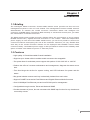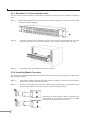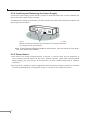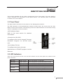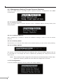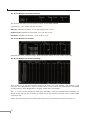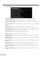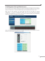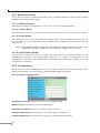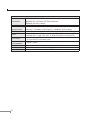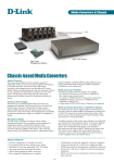
1
Trademarks Copyright PLANET Technology Corp. 2002. Contents subject to revision without prior notice. PLANET is a registered trademark of PLANET Technology Corp. The information in this manual is subject to change without notice. All other trademarks belong to their respective owners. FCC Warning This equipment has been tested and found to comply with the regulations for a Class A digital device, pursuant to Part 15 of the FCC Rules. These limits are designed to provide reasonable protection against harmful interference when the equipment is operated in a commercial environment. This equipment generates, uses, and can radiate radio frequency energy and, if not installed and used in accordance with this user’s guide, may cause harmful interference to radio communications. Operation of this equipment in a residential area is likely to cause harmful interference, in which case the user will be required to correct the interference at his own expense. CE Mark Warning This is a Class A product. In a domestic environment, this product may cause radio interference, in which case the user may be required to take adequate measures. REVISION User’s manual for PLANET Intelligent Media Converter Chassis For Models: WMC-1600R, WMC-1600R48 Rev 1.0 (Dec. 2002) Part No. EM-WMCv1 Table of Contents Chapter 1 INTRODUCTION 1 1.1 Briefing 1 1.2 Features 1 Chapter 2 UNPACKING AND INSTALL 3 2.1 Unpacking 3 2.2 Installation 3 2.3 Deciding How to Install the System 3 Chapter 3 IDENTIFYING FRONT PANEL 7 3.1 Front Panel 7 3.2 LED Indicators 7 Chapter 4 CONFIGURING THE SYSTEM 9 4.1 Configure Through Terminal Emulator/TELNET Program 4.2 Management through Web browser 15 TECHNICAL SPECIFICATIONS 21 Chapter 5 9 Chapter 1 Introduction 1.1 Briefing The Intelligent Media Converter Chassis WMC-1600R series provides 16-slot and one management system in the 19”-rack chassis. The management function enable network administrator to monitor the media converter connection status and configure the converter via SNMP agent, Telnet and Web remotely or via RS-232 console port, yet eases the maintenance of media conversion. The WMC-1600R series media converter chassis allows the connectivity of up to sixteen PLANET Smart Fast / Gigabit Ethernet Converter in one chassis. With the independent power supply on each slot of the WMC-1600R series, you can freely install or remove the converters without interrupting the rest of the networks. Moreover, it’s very flexible that each bay of the media converter chassis can be deployed with PLANET’s smart media converter family. Redundant power supply is also provided to enhance the reliability with option of either 100~240V AC power or -48V DC power. 1.2 Features • High quality 19” Rack-Mountable Chassis installation • Supports up to sixteen slide-in modular media converters hot-swappable • Two power slots for redundant power support with options of 100~240V AC or -48V DC • Reduce the effort of converter maintenance and management, diagnose the status at one time • Two fans brings the air-flow for system cooling, and LED indicators for system and fan status • Bay power isolation ensure each bay is electrically isolated from each other • Support PLANET smart series Fast Ethernet and Gigabit Ethernet Media Converter • One 10/100Mbps Fast Ethernet port and one RS-232 port for management • Configurable through console, Telnet and Web and SNMP • Provide the status of power, fan and converters with SNMP trap function for any chassis and connectivity events. 1 2 Chapter 2 UNPACKING AND INSTALL This chapter provides unpacking and setup information for the Media Converter Chassis. 2.1 Unpacking Open the box of the WMC-1600R and carefully unpack it. The box should contain the following items: • One Intelligent Media Converter Chassis with one power supply installed • One RS-232 Cable • One Power Cord • CD-ROM • Rack mounting Kit • This User’s Manual If any item is found missing or damaged, please contact your local reseller for replacement. 2.2 Installation The site where you place the chassis system may greatly affect its performance. When installing, take the following into your consideration: As with any electric device, you should place the equipment where it will not be subjected to extreme temperatures, humidity, or electromagnetic interference. Specifically, the site you select should meet the following requirements: - The ambient temperature should be between 32 and 104 degrees Fahrenheit (0 to 40 degrees Celsius). - The relative humidity should be less than 90 percent, non?condensing. - Surrounding electrical devices should not exceed the electromagnetic field (RFC) standards for IEC 801?3, Level 2 (3V/M) field strength. - Make sure that the equipment receives adequate ventilation at the rear. Do not block the fan exhaust holes on the rear of the chassis. - The power outlet should be within 1.8 meters of the chassis. 2.3 Deciding How to Install the System We strongly suggest that you install the chassis first, as this is more convenient for you to install media converters into the chassis with ease. The accessories supplied in the product package include: rack-mount screws (8 pcs) and rack-mount brackets (2 pcs). This well-built chassis can be installed in the following ways: 3 2.3.1 Mounted to 19-inch standard rack Use the rack-mount brackets and screws to install the chassis into any EIA 19" standard rack. Step 1: Attach the brackets to each side of the chassis. Apply four screws to each side and secure them tightly. Step 2: Carefully position the chassis into the rack. Align the brackets to the side holes on the rack and use rack screws to secure the chassis with the rack. Step 3: Proceed to the “Connecting to Power” section. 2.3.2 Installing Media Converter The chassis is equipped with sixteen media converter carriers, each of which is fitted into bays of the chassis. Step 1: To install a media converter module onto the chassis, you have to unscrew the bay cover from the desired bay first. Step 2: Unscrew the hand screw counter clockwise by using hand or screwdriver and pull out the media converter out the carrier as shown below. Unscrew the hand screw counter clockwise by using hand or screwdriver and pull the media converter module out on the carrier 4 Step 3: Carefully slide in the module and fasten the hand screw clockwise by using hand or screwdriver until it is fully and firmly fitted into the slot of the chassis. Insert the media converter module into an available slot and fasten the hand screw clockwise by using hand or screwdriver. 2.3.3 Connecting to Power (Power Supply) The chassis ships with only one power supply, and a second power supply option is at your discretion. When the chassis is equipped with two power supplies, you can have the following advanced performance. Hot Swappable – The design of the power system is based on an idea of providing maximum flexibility and redundancy. In this way, you may remove any of the two power supplies without turning off the system. Redundancy – During operation, both power supplies are switched on and share the current load. In case that one of them should fail, the other will instantaneously take 100% of the load without any loss. Similarly, if one power supply is removed from servicing, it can be switched off and removed while the chassis continues functioning. Protection System – The power of each converter bay comes from the two shared power supplies. Each bay is isolated from each other under a certain protection mechanism, so that it is free from any problem that might occur to the power supplies or faulty converter bay. This is the best solution to protect your investment in media converters. Note : There is an optional solution for the backup power, -48 volt DC to DC Power Supply. The chassis system is equipped with one power supply and allows one additional power supply for redundancy. For reliable operation, we suggest that you run the chassis system with two power supplies are in place. Step 1: Connect the supplied AC power cord to the back of the chassis. Step 2: Attach the plug into a standard AC outlet with a voltage range from 100~240 VAC. Step 3: Turn on the chassis system by flipping the switch beside the receptacle to ON position. The LED on the front panel of power supply will come on then. 5 2.3.4 Installing and Removing the Power Supply To remove a power supply out the chassis, you have to loose the hand screw counter clockwise and pull out the power supply from the chassis. To install a power supply to the chassis, you have to fasten the hand screw clockwise and slide in the power supply to the chassis. You can slide in and out the power supply from the bay, fasten or loose the hand screw clockwise or counter clockwise by using hand or screwdriver. Note: If the Chassis System needs to work alone, you can stick up four Rubber foot below the chassis! 2.3.5 Power Notice: 1.The device is a power-required device, it means, it will not work till it is powered. If your networks should active all the time, please consider using UPS (Uninterrupted Power Supply) for your device. It will prevent you from network data loss or network downtime. 2.In some area, installing a surge suppression device may also help to protect your switch from being damaged by unregulated surge or current to the media converter. 6 Chapter 3 IDENTIFYING FRONT PANEL This section identifies all the major components of the front panel. The front panel is shown, followed by a description of each panel feature. The indicator panel is described in detail in the next chapter. 3.1 Front Panel The figure below shows the front panels of the Management Module. The LED indicators of the Management Module include Power On, Power Fail, Fan Fail, MGM, Console and Link/ACT. The following shows the LED indicators for the Switch along with an explanation of each indicator. •LED Indicator Panel Refer to the next section for detailed information. •Console Port (RS-232) To configure the device through Terminal Emulation Program via RS-232 serial port. •10/100Base-TX Port To configure the device through Web Browser or TELNET program via LAN Ethernet. 3.2 LED Indicators There are two powers at the rear and will indicate on the front panel the status of the power and fan: PWR On PWR Fail Fan Fail MGM Console LNK/ACT Lights Lights Lights Blinks Lights Blinks Blinks Lights Blinks Green Amber Amber Green Amber Green Amber Green Green when when when when when when when when when the power is inserted the power is inserted and it is fail the fan is fail to work the device CPU is working the CPU works fail the data is transmitting transmitting the wrong data link to networking Ethernet link is activity 7 8 Chapter 4 CONFIGURING THE SYSTEM This chapter provides network managers and system administrators with information about how to configure the WMC-1600R via the Management interface. 4.1 Configure Through Terminal Emulator/TELNET Program 4.1.1 Console and Terminal Emulator program setting The WMC-1600R can be accessible using a terminal or terminal emulator attached to the RS-232 serial port. 1.Locate correct DB9 serial port cable with female DB9 connector. 2.Attach the DB9 serial port female cable connector to the male DB9 serial port connector on the chassis system. 3.Attach the other end of the DB9 serial port cable to a remote the workstation. 4.By default, the Management Module uses the following serial port parameter values: Bits per second 57600 Stop bits 1 Data bits 8 Parity NONE Flow Control NONE The default Login name and password is both “root". 4.1.2 TELNET program setting The WMC-1600R can be accessible using TELNET through LAN. 1. Run TELNET program. 2. Enter the IP address "192.168.1.1" (the factory-default IP address setting). 3. The default Login name and password is both "root". 9 4.1.3 Management Setting Through Terminal Emulator There are three items in the Main Menu, System Function, Configuration and SNMP Configuration. 4.1.3.1 System Function There are three items in System Function menu, “Software Reboot, Factory Reset, and Image Update. 4.1.3.1.1 Software Reboot After configuring, it needs to reboot the software setting in order to run the device properly. 4.1.3.1.2 Factory Reset This function is to set the device back to the default setting in case of the messy setting. 4.1.3.1.3 Image Update The section is to set the TFTP Server IP Address first, and the default address was set to “192.168.1.2”. The Image File can be updated by uploading the image file from the TFTP server. Note: The content of the image file will write the whole firmware of the management module, please be sure that the image file is correct. 4.1.3.2 Configuration To set the Software Reboot, Factory Reset and Image Update. 10 There are four items in the Configuration menu, “General Configuration, System Configuration, Media Converter Chassis and Media Converters. 4.1.3.2.1 General Configuration Hardware revision: noted the version of the hardware. BIOS revision: noted the version of the BIOS. Firmware revision: noted the version of the firmware. Change Password: the changing of the admit password. Confirm Password: to confirm the setting of admit password. System Name: to authorize the device system name. Location: to show the device where it is located. Refresh time: to set the refreshing time of the device through the web. 4.1.3.2.2 System Configuration MAC Address: will show out the MAC address of the device. IP Address: to allocate an IP address for the device, the default IP is “192.168.1.1”. Subnet Mask: to set the Subnet Mask, the default is “255.255.255.0”. Default Gateway: to set the gateway address, the default is “192.168.1.254”. NOTE: After configuring the system device, need to press the save button to save the setting. 11 4.1.3.2.3 Media Converter Chassis The screen will show out the power status of the WMC-1600R. V stands for “yes” and X stands for “No”. Plug in: indicates if Power 1 or 2 was plugged in or not. Power Fail: indicates if the Power 1 or 2 is fail or not. Fan Fail: indicates if the Fan 1 or 2 is fail or not. 4.1.3.2.4 Media Converters Indicates the Link, Duplex mode, Speed and Fail status of each media converter. 4.1.3.2.5 Media Converters Setting This screen is to set the Device function of LLCF and Link Enable; the Media 1 LLR function, Auto-Negotiation, Speed, Duplex Mode, Flow Control and Link Enable; the Media 2 LLR function, Auto-Negotiation, Duplex mode and Link Enable. The “*” in the screen stands for N/A (not available), and the management interface will detect if the slot has the function in it and will let you set the function exist on the media converter slot. Select the slot and press the space bar button to choose which function to open up. 12 Device LLCF: Link Loss Carry Forward, “on” or “off”. Enable: to enable the link of the Device, “on” or “off”. Media 1 LLR: Link Loss Return, “on” or “off”. Auto: “A” for Auto-Negotiation or “F” for “forced Mode”. Speed: to select the speed of the copper port, “10M”, “100M” or “1G”. Dup: Duplex mode, “F” for Full Duplex or “H” for Half Duplex. FC: Flow Control, “on” or “off”. Enable: to enable the link of the Media 1, “on” or “off”. Media 2 LLR: Link Loss Return, “on” or “off”. Auto: “A” for Auto-Negotiation or “F” for “forced Mode”. Dup: Duplex mode, “F” for Full Duplex or “H” for Half Duplex. Enable: to enable the link of the Media 1, “on” or “off”. Note: Some of the function can be control only depends on the Smart Media Converter 4.1.3.2.6 Redundant Backup Setting The redundant function is to change the master line to the slave line in case of the linking fails happen. The Redundant functions were set fixed, the master slot is slot 1 (odd number slot) and the slave slot is slot 2 (even number slot), and there are eight redundant groups in all. The “Act” will indicate what slot is active. When the slave slot is active, and we need to transfer again to the master slot, push on the restart button. 13 4.1.3.3 SNMP Configuration Get Community Name: to get the device community name (default = public). Set Community Name: to set the device community name (default = private). Trap Community Name: to authorize the device trap community name (default = public). Trap Host IP Address: to set the trap host IP address (same as monitoring station IP address). Cold Start trap: to set the trap for rebooting the device (default = enable). Warm Start trap: to set the trap when the device had been reset (default = enable). Authentication Fail Trap: to set the warning trap when the community name of the device and workstation are different (default = enable). Power Fail Trap: to set the Power Fail Trap (default = enable). Fan Fail Trap: to set the fan fail trap (default = enable). MC Plug-in Trap: to set the trap when a Media Converter module has been plugged in (default = enable). MC Pullout Trap: to set the trap when the Media Converter module has been pulled out (default = enable). MC Broken trap: to set the trap when the Media Converter module was broken (default = enable). MC Link up trap: to set the trap when a linking is connected (default = enable). MC Link down trap: to set the trap when a linking is disconnected (default = enable). MC Active Slot Xchg trap: to set the trap when there is a redundant function activated (default = enable). MC Active Slot Lose trap: to set the trap when the redundant function is fail (default = enable). 14 4.2 Management through Web browser The WMC-1600R is accessible using a Web browser (IE explorer, Netscape Communications, etc.) to open up the chassis monitoring system. The default IP Address for the chassis system is “192.168.1.1”, and the default Login name and password is both “root”. After enter its web interface, the Home Page will show out the page for general configuration. To set the management system, click on the left side menu, System Function and Configuration, the center screen will then show the status and configuration screen for the menu you clicked on the left side. Click on the Media Converter slot and it will appear a screen for you to monitor or control, depend on what media converter you are using. 15 4.2.1 System Function There are four items in System Function menu, “Software Reboot, Factory Reset, Image Update and Configuration Update. 4.2.1.1 Software Reboot Reboot the management module in order to run the new setting properly. 4.2.1.2 Factory Reset This function is to set the device back to the default setting in case of the messy setting. 4.2.1.3 Image Update The section is to set the TFTP Server IP Address first, and the default address was set to “192.168.1.2”. The Image File can be updated by uploading the image file from the TFTP server. Note: The content of the image file will write the whole firmware of the management interface, please be sure that the image file is correct. 4.2.1.4 Configuration Update The section is explaining how to upload and download the configure setting of the management interface. The Configuration Upload is to restore a setting file to the management interface. The Configuration Download is to backup the setting from the management interface. 4.2.2 Configuration There are five items in Configuration menu, General Configuration, System Configuration, SNMP Configuration, Location Setting and Redundant Backup Setting. 4.2.2.1 General Configuration Hardware revision: noted the version of the WMC-1600R. BIOS revision: noted the version of the BIOS. Firmware revision: noted the version of the firmware. Change Password: the changing of the administrator password. Confirm Password: to confirm the setting of administrator password. 16 System Name: to authorize the device system name. Location: to show the WMC-1600R where it is located. Refresh time: to set the refreshing time of the device through the web. NOTE: After configuring the system device, need to press the save button to save the setting. 4.2.2.2 System Configuration MAC Address: will show out the MAC address of the Management interface. IP Address: to allocate an IP address for the Management interface, the default IP is “192.168.1.1”. Subnet Mask: to set the Subnet Mask, the default is 255.255.255.0”. Default Gateway: to set the gateway address, the default is “192.168.1.254”. NOTE: After configuring the system device, need to press the save button to save the setting. 4.2.2.3 SNMP Configuration Get Community Name: to get the device community name (default = public). Set Community Name: to set the device community name (default = private). Trap Community Name: to authorize the device trap community name (default = public). Trap Host IP Address: to set the trap host IP address (same as monitoring station IP address). Cold Start trap: to set the trap for rebooting the device (default = enable). 17 Warm Start trap: to set the trap when the device had been reset (default = enable). Authentication Fail Trap: to set the warning trap when the community name of the device and workstation are different (default = enable). Power Fail Trap: to set the Power Fail Trap (default = enable). Fan Fail Trap: to set the Fan fail trap (default = enable). MC Plug-in Trap: to set the trap when a Media Converter Module has been plugged in (default = enable). MC Pullout Trap: to set the trap when the Media Converter Module has been pulled out (default = enable). MC Broken trap: to set the trap when the Media Converter Module was broken (default = enable). MC Link up trap: to set the trap when a linking is connected (default = enable). MC Link down trap: to set the trap when a linking is disconnected (default = enable). MC Active Slot Xchg trap: to set the trap when there is a redundant function activated (default = enable). MC Active Slot Lose trap: to set the trap when the redundant function is fail (default = enable). 4.2.2.4 Location Setting Assign each slot’s location or name in order to remember in where each slot was connected. 18 4.2.2.5 Redundant Backup Setting The redundant function is to change the master line to the slave line in case of the linking fails happen. The Redundant functions were set fixed, the master slot is slot 1(odd number slot) and the slave slot is slot 2(even number slot), and there are eight redundant groups in all. The “Act” will indicate what slot is active. When the slave slot is active, and we need to transfer again to the master slot, we need to push on the restart button. 19 20 Chapter 5 TECHNICAL SPECIFICATIONS Capacity Material Chassis System Sixteen bays for housing up to sixteen media converters Steel One power supply provided, hot-swappable Power *A second power supply for load-sharing is optional, also hot- Cooling Dimensions Net Weight swappable Two fans mounted together with the power supply or alone at the rear W415 mm × D 390mm × H89 mmStandard 19” size, 2 U 7.2kg approx. (*Only one power supply included) Rated Voltage Speed Air Delivery Noise Level Bearing System Dimensions Inputs Power Consumption Temperature Humidity Overload Protection Emissions Fan 12V DC 3200 RPM +/- 250 RPM 42.5 CFM per min. 36.5dB(A) Precise ball bearing system 80 × 80 × 25 mm Power Supply 100 to 240 VAC, universal power supplyor -48V DC 150 watts. (max.) Operating:0°~40°C, Storage: -10°~50° C Operating:10% ~ 90%, Storage: 5% ~ 90% All outputs protected from short circuit condition, automatic recovery FCC Class A, CE Mark Class A, VCCI Class A 21 Management Module IEEE802.3 10Base-T Ethernet Standards IEEE802.3u 100 Base-TX Fast Ethernet Protocol Data IEEE802.3x flow control CSMA/CD Ethernet: 10Mbps (half duplex), 20Mbps (full duplex)Fast Transfer Rate LED Indicators Cable Fixed Ports Power Consumption Temperature Humidity Emissions 22 Ethernet: 100Mbps (half duplex), 200Mbps (full duplex) Power On, Power Fail, Fan Fail, MGM, Console, LNK/ACT 10BaseT: 2-pair UTP Cat. 3,4,5; EIA/TIA- 568 100-ohm STP 100Base-TX: 2-pair UTP Cat. 5; EIA/TIA-568 100-ohm STP 1 x 10/100Base-TX port 1 x 9 pin RS-232 Console port 3 watts. (Max.) Operating: 0° ~ 50° C, Storage: -10° ~ 70° C Operating: 10% ~ 90%, Storage: 5% ~ 90% FCC Class A, CE Mark Class A, VCCI Class A Part No.:EM-WMCv1