1
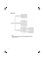
Digital High Definition Tuner
SH-DT510
Operating instructions
1
Safety First
VENTILATION CAUTION
When installing this unit, make sure to leave space
around the unit for ventilation to improve heat
radiation (at least 8 cm at top, 5 cm at rear, and 5
cm at each side).
WARNING
Slots and openings in the cabinet are provided for
ventilation to ensure reliable operation of the
product, and to protect it from overheating. To
prevent fire hazard, the openings should never be
blocked or covered with items (such as newspapers,
table-cloths, curtains) or by operating the
D3-4-2-1-7b_A_En
equipment on thick carpet or a bed.
2
CAUTION
The STANDBY/ON switch on this unit will not
completely shut off all power from the AC outlet.
Since the power cord serves as the main disconnect
device for the unit, you will need to unplug it from
the AC outlet to shut down all power. Therefore,
make sure the unit has been installed so that the
power cord can be easily unplugged from the AC
outlet in case of an accident. To avoid fire hazard,
the power cord should also be unplugged from the
AC outlet when left unused for a long period of time
D3-4-2-2-2a_A_En
(for example, when on vacation).
STANDBY/ON Button
STANDBY: When set to the STANDBY position, the
main power flow is cut and the unit is no longer
fully operational. A minute flow of power feeds
the unit to maintain operation readiness.
STANDBY Indicator
The red indicator is lit when the unit is in the
standby mode.
WARNING
This product equipped with a three-wire grounding
(earthed) plug - a plug that has a third (grounding)
pin. This plug only fits a grounding-type power
outlet. If you are unable to insert the plug into an
outlet, contact a licensed electrician to replace the
outlet with a properly grounded one. Do not
defeat the safety purpose of the grounding plug.
D3-4-2-1-6_A_En
3
TABLE OF CONTENTS
Safety First .............................................................................. 2
Chapter 1: Introduction ......................................................... 6
Summary of Features ........................................................................................ 6
Getting Started ................................................................................................... 7
Menu Tree .......................................................................................................... 8
Chapter 2: Installation ........................................................... 9
Introduction ...................................................................................... 9
Package Contents ............................................................................. 9
Description of Equipment ............................................................... 9
Remote Control Unit (RCU) ................................................................................ 9
Functions Of RCU Buttons ............................................................................. 10
Front Panel ........................................................................................................... 11
Rear Panel ............................................................................................................ 11
Physical Installation ............................................................................................ 12
Sample Configurations ....................................................................................... 13
HDMI Connection ........................................................................................... 13
High Definition TV(Y/Pb/Pr) Connection ..................................................... 13
S-Video Connection ........................................................................................ 14
Composite Video Connection ......................................................................... 14
Antenna Loop Connection .............................................................................. 15
Digital Audio Connection ............................................................................... 15
Chapter 3: Channel Setting ................................................. 16
Introduction .................................................................................... 16
INSTALLATION ............................................................................ 17
QUICK SCAN ..................................................................................................... 17
AUTO SCAN ........................................................................................................ 18
MANUAL SCAN ................................................................................................. 19
CLEAR ALL DATA ............................................................................................ 19
4
General Setting ............................................................................... 20
TIME SETUP ...................................................................................................... 20
AUDIO SETUP .................................................................................................... 20
i - PLATE SETUP ............................................................................................... 21
SOFTWARE ........................................................................................................ 22
CURRENT VERSION .................................................................................... 22
INSTALL NEW S/W ...................................................................................... 22
Chapter 4: Using the Tuner ................................................. 23
Introduction .................................................................................... 23
Switching the Tuner On and Off .................................................. 23
Using the Menus and Remote Control Unit (RCU) .................... 23
Selecting Favorite Channels ............................................................................... 24
Favorite Channel List ......................................................................................... 24
PARENTAL GUIDANCE ................................................................................... 25
CHANGE PASSWORD ...................................................................................... 25
i-PLATE (INFORMATION PLATE) ............................................................... 26
TELETEXT / Closed Caption ........................................................................... 27
SLEEP .................................................................................................................. 28
Appendix A: Interference with The HDTV Tuner ............. 29
Appendix B: Troubleshooting .............................................. 30
Appendix C: DTV CHANNEL TABLE .............................. 32
Appendix D: Specifications .................................................. 34
Glossary ................................................................................. 36
5
Chapter 1: Introduction
Digital High Definition Tuner's Functions
The SH-DT510 digital High Definition tuner opens up a new world of free-toair terrestrial programming. This tuner can receive channels from
VHF/UHF band TV station's digital signals. All the major terrestrial free-to-air
digital station numbers currently available in your area are listed in the onscreen menu. To access the high quality digital programs, simply select
the channel number on your remote control.
The SH-DT510 tuner is MPEG 2 / DVB-T (digital video broadcast-terrestrial)
compliant, delivering crisp video images and excellent sound. It supports a
broad signal range from 51-858 MHz, and can be easily programmed for all
the channels within the VHF/UHF frequency spectrum.
Summary of Features
The SH-DT510 supports digital functions that are MPEG 2-DVB compliant.
Just follow the friendly On-Screen Display (OSD) to guide you through all
the steps necessary to configure your tuner ; then begin enjoying all the
video and audio channels with crisp picture quality and the crystal clear
sound.
The key features of the receiver are described below:
Front Panel
The Front Panel of the tuner includes an LED display with important
channel information. For more information on the Front Panel refer to
Chapter 2
Remote Control Unit ( RCU )
The Remote Control Unit (RCU) provides access to a full range of the
system features. In addition to providing access to terrestrial programs with
the channel and volume controls, it can also be used to access all the
system menus.
In particular, the RCU has to be used to configure the transmission
parameter settings, select the channels you want to include in the program
list, as well as access many other configuration options. For more
information on using the RCU, refer to Chapter 2 and to the various system
operations described in Chapter 3.
6
System Menus
All the tuner's features can be accessed through the system menus. These
menus can be accessed with simple point and click actions, using the
navigation and select buttons on the RCU. The menus include items such as
Transmission Parameter Configuration, Channel List, Audio Options, and
Parental Lock. For more information on using the menu system, refer to the
simple "Menu Tree" described later in this chapter, or refer to the more
detailed menu descriptions in Chapters 3 and 4.
Parental Lock
Channels which are not suitable for viewing by children can be protected by
using the parental lock feature. (Password is initially set to "0000".)
Getting Started
This section provides a brief introduction to the SH-DT510 tuner. If a
service provider or professional system installer has already installed your
digital High Definition tuner and antenna, then this section should provide all
the
information you need to start using the tuner. For more information on basic
operations, refer to Chapter 3.
Before connecting any devices to the tuner, refer to the
"Safety First" page.
7
Menu Tree
Note:
You need to enter a " Password " to access some of the functionality in the menu.
Password is initially set to "0000". For more information, please refer Chapter 4
"CHANGE PASSWORD".
8
Chapter 2: Installation
Introduction
If your service provider or system installer has already set up the antenna and
connected the tuner, then you can start the operations specified in Chapter 4.
However, if you are setting up the system by yourself, please read through this
section and be sure you follow all of the precautions listed under "Safety First".
Package Contents
Unpack the tuner and check that all of the items listed below are included.
•
•
•
•
•
•
•
SH-DT510 Digital High Definition tuner
Remote Control Unit (with 2 AAA batteries)
Audio Cable
Video Cable
Y/Pb/Pr cable
Power Cable
Operating instructions
Description of Equipment
The SH-DT510 digital High Definition tuner is designed to receive Free-To-Air
digital programming from VHF/UHF terrestrial TV channels. Please see the following
description:
Remote Control Unit (RCU)
The RCU provides easy access to all of the tuner's functions, including selecting
channels and using the menus. It uses infrared signals and must be operated at a
distance of three to four meters from the receiver. When using the RCU, be sure that
there is a direct line of sight to the tuner.
The batteries for the RCU are packaged separately. Before
you start using the tuner, please install these batteries with
+/- terminals aligned as per the picture below.
2
Note:
• To avoid damaging the RCU through battery leakage,
1
discard any depleted or old batteries.
• When disposing of used batteries, please comply
with governmental regulations or environmental public
instruction's rules that apply in your country/area.
9
Functions Of RCU Buttons
The buttons on the remote control are described as follows:
• STANDBY/ON: Switches the tuner between ON and
STANDBY modes.
• Numeric Buttons: For entering channel number or
password.
• INFO: Displays i-Plate providing information about the
current channel.
• MENU: Activates the On-Screen Menu.
• FAV.: Selects the Favorite channel list.
• Direction buttons: Move through menus or submenus.
• ENTER: Displays channel list or enters highlighted menu
feature.
• CH+/CH-: Selects viewing channel one up or down in
program list.
• VOL+/VOL-: Raises or lowers audio volume.
• A.RATIO: Adjusts the picture height/width ratio between
16:9 and 4:3.
- 16:9(Wide Screen Display) : to display 16:9 program on 16:9
TV screen to display 4:3 program on 4:3 TV screen.
- 4:3(16:9 Letterbox): to display 16:9 program on 4:3 TV screen
in letterbox.
- 4:3(16:9 Crop) : to display 16:9 program cropped on 4:3 TV
screen.
MUTE
SLEEP
1
2
3
4
5
6
7
8
9
AUDIO
0
INFO
FAV.
LIST
STANDBY
/ON
V. FORMAT
A.RATIO
TELETEXT
TTX
RETURN
CH
ENTER
MENU
VOL
DIGITAL TUNER
• V.FORMAT: Toggle between "PAL (625i)", "1080i50(1125i)", "720P-50(750P)", and "576P-50(625P)" video format through Y/
Pb/Pr video format connector to optimise resolution.
Note:
PAL, 625i and 720x576i are identical,
1080i-50, 1125i and 1920x1080i are identical,
720P-50, 750P and 1280x720p are identical,
576P-50, 625P and 720x576p are identical.
• MUTE: Audio mute toggle.
• TTX: For Teletext Emulation and DVB Subtitle.
• RETURN: Exits main menu or one level up from submenus, and exits from the
EPG and information screens.
• LIST: Displays the complete channel /program list.
• AUDIO: Show the multiple table to move / buttons for selecting language
• Colour buttons: 4 colour buttons are prepared to be used for TELETEXT operations.
Use for fast access a group or block of Teletext pages.
• SLEEP: Sets the sleep timer.
10
Front Panel
The buttons and indicators on the Front Panel of your SH-DT510 are
described in the following picture and table:
Standby / On
LED Display
DIGITAL HIGH DEFINITION TUNER
SH-DT510
STANDBY/ON
MENU/
ENTER
RETURN
LED Indicators
Rear Panel
The rear panel carries connectors for attaching VHF/UHF antenna and other
home entertainment equipment. To ensure highest quality video output, it
is recommended to use (in order of preference) HDMI, Component Video,
S-Video, Composite Video.
HDMI
RF In
VHF/UHF
Antenna
Composite
Video Out
RF IN
Data port
VIDEO
Y
COAXIAL
L
OPTICAL
R
PB
AC IN
PR
RF OUT
S- VIDEO
ANT
RF Out
COMPONENT
VIDEO
VIDEO OUT
S-Video
Component
Video Out
HDMI OUT
AUDIO OUT
Digital
Audio Out
SERVICE
ONLY
Audio
Out
AC Power
11
Terminals
Description
S-Video Out
Connects to the S-Video input on your TV or VCR.
Data Port
For service use only.
RF In
Connects the VHF/UHF antenna. This connector
accepts input signals ranging from 51 to 858 MHz.
Composite Video Out
Connects to the video input on your TV, VCR or DVR.
Audio Out
(L, R)
Connects to the audio input on your TV, VCR,
DVR or stereo system.
RF Out
Connects to TV or VCR RF input (for video and
mono audio signals).
AC IN
Connecting to mains supply and plug the receiver
into the main, the power source from 240 Vac, 50 Hz
Digital Audio Out
(Optical and Coaxial)
Connects to the digital (Optical and Coaxial)
audio input on a home theatre surround system.
Component Out
(Y/Pb/Pr)
Connects to the component (Y/Pb/Pr) video input
on your TV set.
HDMI Out
Connects to the HDMI input on your TV.
Physical Installation
There are many ways to connect the Digital High Definition tuner to your TV,
depending on the equipment and connection types you have. However, for
the best video/audio quality, use the best quality HDMI Terminal if available.
Always disconnect the tuner from the power source prior to connecting or
disconnecting.
12
Sample Configurations
HDMI Connection
VHF/UHF
Antenna
RF IN
VIDEO
Y
COAXIAL
L
OPTICAL
R
PB
AC IN
PR
RF OUT
S- VIDEO
ANT
COMPONENT
VIDEO
VIDEO OUT
HDMI OUT
AUDIO OUT
SERVICE
ONLY
HDMI
AC Power
High Definition TV(Y/Pb/Pr) Connection
VHF/UHF
Antenna
RF IN
VIDEO
Y
COAXIAL
L
OPTICAL
R
PB
AC IN
PR
RF OUT
S- VIDEO
ANT
COMPONENT
VIDEO
VIDEO OUT
HDMI OUT
Video
AUDIO OUT
SERVICE
ONLY
Audio
AC Power
13
S-Video Connection
VHF/UHF
Antenna
RF IN
VIDEO
Y
COAXIAL
L
OPTICAL
R
PB
AC IN
PR
RF OUT
S- VIDEO
ANT
COMPONENT
VIDEO
VIDEO OUT
HDMI OUT
AUDIO OUT
S-Video
AC Power
SERVICE
ONLY
Audio
Note:
Connecting video through S-Video, OSD can not work under 1080i / 720p
and 576p modes. Please connect your TV to Y/Pb/Pr or HDMI output for
OSD properly displaying under 1080i / 720p & 576p modes.
Composite Video Connection
VHF/UHF
Antenna
RF IN
VIDEO
Y
COAXIAL
L
OPTICAL
R
PB
AC IN
PR
RF OUT
S- VIDEO
ANT
VIDEO OUT
Video
AC Power
14
COMPONENT
VIDEO
HDMI OUT
AUDIO OUT
Audio
SERVICE
ONLY
Antenna Loop Connection
Using RF Output to connect with VCR or Secondary TV
The RF OUT only support signal loop-thru but not
the re-modulation for the received program.
VHF/UHF
Antenna
RF IN
VIDEO
Y
COAXIAL
L
OPTICAL
R
PB
AC IN
PR
RF OUT
S- VIDEO
ANT
COMPONENT
VIDEO
VIDEO OUT
HDMI OUT
AUDIO OUT
SERVICE
ONLY
RF Out
Video
AC Power
Audio
VCR
Digital Audio Connection
VHF/UHF
Antenna
Digital
Audio
RF IN
or
VIDEO
Y
COAXIAL
L
OPTICAL
R
PB
AC IN
PR
RF OUT
S- VIDEO
ANT
COMPONENT
VIDEO
VIDEO OUT
HDMI OUT
AUDIO OUT
SERVICE
ONLY
AC Power
15
Chapter 3: Channel Setting
Introduction
After finishing the hardware installation as described in Chapter 2, switch on the
tuner.
It will display Data base is Empty and instruct you to press the "MENU"
button on the remote control.
The following menu will be displayed after pressing the "MENU" button.
• Initial Screen
Menu
Description
CH SETUP
Set up favorite channels in the Favorite list, set
up, control and activate Parental Guidance and
Password
INSTALLATION
Search channels using one of three scan modes.
SET UP
General setup for the tuner, update the tuner's
software version
Note:
Use the "MENU" button on the RCU to display the Main Menu, the arrow
buttons to move through the menus, the "ENTER" button to choose specific
items, and "RETURN" button to return to the previous menu.
16
INSTALLATION
• INSTALLATION MENU gives 4
different sub-menu.
QUICK SCAN
AUTO SCAN
MANUAL SCAN
CLEAR ALL DATA
QUICK SCAN
If you live in one of the cities or regions listed in the QUICK SCAN menu,
select your city or region and start scanning all digital TV channel signals .
• On the user installation page, select
QUICK SCAN.
• Scroll up or down the list to find
the city or region that you live in
and press "ENTER" button to
start scanning.
• The tuner will scan through the
channels available in your area.
Note :
The frequencies of these channels are
preset in the tuner's database. If the
channel frequency is changed by the
local TV station or a new channel
commences broadcasting, you will have
to find these channels using MANUAL
SCAN.
17
AUTO SCAN
Auto Scan searches for digital programs on all channels, 5 to 69, through
the VHF and UHF bands.
• Select AUTO SCAN and press
"ENTER" button.
• Select YES then press "ENTER"
button to start channel search.
• The tuner starts scanning from
channel 5 to channel 69. The
percentage bar shows the progress
made.
• Once the digital TV signal is
scanned, the channel number and
program name will be shown on
the Program List above the
percentage bar.
• Scanning will finish on channel 69,
after that, you can press the
"RETURN" button to leave this
window and start watching DTV
programs.
18
MANUAL SCAN
Manual Scan search the channel based on user request frequency and
bandwidth.
• On the Installation page, select
MANUAL SCAN and press
"ENTER" button.
• Select channel number. Be sure you
know the channel number and its
RF frequency.
• Check FREQUENCY,
BANDWIDTH and PRIORITY to
ensure that these parameters are
correct, then highlight Start Scan
and press "ENTER" button to start
the scan.
• When the tuner locks onto a channel, the words "Start Scan" will change to
"Get Channel Success" (Ideally it should be "Get Channel Success" but if
difficult to change OSD, leave as it is). You can press RETURN twice to leave the
Installation page and watch the program immediately or continue scanning for
other channels. If you want to know the signal level and SNR (Signal to Noise
ratio) while watching a digital TV channel, navigate to this page.
• If the signal is not locked, "Start Scan" will show "Timeout error". You can try
to scan the signal again, or refer to the Signal Level bar and Quality band to
align the antenna to improve your signal reception. Contact an antenna installer
if you cannot lock onto the signal after trying all of the suggestions in this
manual.
CLEAR ALL DATA
• This option allows you to reset the
tuner to its factory settings, losing
all channels and setup changes you
have made. Select CLEAR ALL
DATA to reset the tuner.
WARNING:
Do not choose this option if you do
not understand the functioning of the
tuner. No viewing channels will remain
afterwards. Setup procedures and
scanning will have to be performed
again after taking this step.
19
General Setting
• Selecting SET UP will display this
sub-menu.
TIME SETUP
AUDIO SETUP
i - PLATE SETUP
SOFTWARE
TIME SETUP
• TIME SETUP sets the time in "TIME
ZONE". Use the ""and ""
buttons to select the local time zone
you are located in and press the
"ENTER" button.
Note :
A correct time zone setting can help box
to display the correct time in the i-PLATE.
All other time related information like service
duration for NOW and NEXT extended
information would show the time
information according to the time zone
you selected.
AUDIO SETUP
• Selecting this option allows you to select
the appropriate DIGITAL OUTPUT
for your Audio equipment. Also you
can change the language by selecting
AUDIO LANGUAGE.
Note :
The audio language you select will only
work when the broadcasting signal carries
that language sound track.
20
i - PLATE SETUP
• On selecting this option from the above
menu, you can change the i-PLATE
display time and format.
21
SOFTWARE
• When you select the SOFTWARE
menu, there are two sub-menus
displayed:
CURRENT VERSION
INSTALL NEW S/W
CURRENT VERSION
• Under the CURRENT VERSION submenu, the ID number of installed
hardware and software versions of
the tuner are displayed.
INSTALL NEW S/W
• Service use only
22
Chapter 4: Using the Tuner
Introduction
Once the channels are downloaded, you can start enjoying the full range of video
and audio programs. Operating the tuner is extremely easy. You can control the
show tuner directly from the Front Panel or with the RCU as described below. The
tuner's menu provides access to a listing of all the channels configured on your
tuner and parental controls that allow you to access or restrict sensitive programming,
as well as the various audio options.
Switching the Tuner On and Off
You can use the Standby/On button on the RCU to alternate the tuner between
ON and Standby modes.
Using the Menus and Remote Control Unit (RCU)
Just by pressing the buttons on the RCU, you can operate most common functions,
such as selecting the programs, displaying Information and adjusting the volume.
But to access some of the more complicated functions (such as Digital TV channel
setting, program listing and system settings) or to configure the tuner, you will
need to use the on-screen menus. Most functions can be accessed either via the
buttons on the Front Panel of the tuner or with the RCU. However, for items that
require numeric inputs, the RCU must be used. There are two ways to access the
various menu items:
1. Press the "MENU" button, highlight the required item with the navigation button
(///), press "ENTER" button and continue moving through the menus
until you find the item you desire.
2. Select LIST, FAV. from RCU to directly access the service.
To close the menu or navigate back in the menu hierarchy, press the "RETURN"
button.
23
Selecting Favorite Channels
• Under the "CH SETUP" sub-menu,
you can select "SELECT FAVORITE"
to set up favorite channels.
• Use "" and "" buttons to select
the channel, use "" and ""
buttons to select "FAV.1" or "FAV.2"
• When you highlight "FAV.", the
direction icon will show.
• After you have made all the selections,
press "ENTER" button to register
them.
Favorite Channel List
• When you are watching
Broadcasting, you can press the
"FAV." button on the remote
control to call up the Favorite List.
• Use "" and "" buttons to browse
through the program lists and
highlight the channel you want to
watch, then press "ENTER" button.
24
PARENTAL GUIDANCE
• Under CH SETUP sub-menu, you can
select PARENTAL GUIDANCE to
block programs.
• Use "" and "" buttons to select
the Rating, press "ENTER" button
to confirm the setting.
• When DTV programs broadcasted
are accompanied by the ratings, the
programs will be blocked based on
your setting, then you have to enter
PASSWORD to resume watching the
program. Pass word is set to "0000"
at factory initial setting.
CHANGE PASSWORD
• You can change the password by
selecting the CHANGE
PASSWORD. Entering desired
Password, and re-type it again to
confirm.
• Password is set to "0000" at
factory initial setting.
25
i-PLATE (INFORMATION PLATE)
• While watching DTV you can press
the "INFO" button to activate
extended program information.
• The i-PLATE will pop up with the
following information,
- Current Channel Number
- Network Name
- Program Name
- Audio Output (PCM or Dolby
Digital)
- Digital / Analog TV signal
- Teletext
- Current Local Time
- Date and Month
• While the i-PLATE is still on the screen,
you can press "INFO" button again
to call up the extended program
information of the current TV channel
(NOW) .
• Press the "INFO" button again and
you can call up the extended program
information of the next program
(NEXT).
• To leave, you simply press "RETURN"
button.
26
TELETEXT / Closed Caption
• When the i-PLATE indicated that
Teletext / Closed Caption data is
available on the current channel, you
can press the " TTX " button on the
remote control to display it on the
TV screen.
• 4 Colour buttons are assigned for TTX.
You can select a group or block of
pages displayed in the coloured
brackets at the bottom of the screen
by pressing the corresponding colour.
(RED/GREEN/YELLOW/BLUE)
27
SLEEP
When the selected time elapses, the Sleep Timer automatically places the
system into the standby mode.
Press "SLEEP" button to select the desired time.
• The timer starts counting.
• To cancel the Sleep Timer, select "OFF"
by pressing "SLEEP" button.
• Each time you press "SLEEP" button
the selection is switched as below:
• The factory default is "OFF".
28
Appendix A: Interference with The HDTV Tuner
Weather Induced Signal Fading
Natural calamities may affect signal reception. If the terrestrial TV programming is
often affected by inclement weather conditions, there are a few basic steps you
can take to improve reception:
1. Make sure your antenna is aimed to receive the strongest possible signal.
2. If this does not solve the problem, consider installing a larger antenna with
higher gain. This can help to gather more signal transmitted from the TV station.
3. If you live in an area subject to frequent snow or freezing rain, you may need to
install a deicing system to eliminate the accumulation of unwanted ice, snow
or moisture from the surface of your antenna.
4. If the program reception is not good affected by heavy winds, you can stabilize
the antenna mast with cables.
Home Appliances' Interference
When you turn on home appliances like air conditioner and washing machine
while you are using the tuner, in a very rare case It is possible that the power
surge caused by turning on these home appliances may interfere tuner's performance.
In such case we suggest that you use a different AC power source (different AC
outlet) between SH-DT510 and other home appliances (devices which can generate
AC surge), or use a surge protector, available from computer, hardware or electrical
stores.
29
Appendix B: Troubleshooting
If you encounter any problems with the tuner, look through this section for a description
of your problem. Try solving the problem by following the given solutions. However,
if after attempting all the recommended actions you still cannot solve the problem,
please contact PIONEER SERVICE AND PARTS CENTER.
If the unit does not operate normally due to external effects, disconnect the power
plug from the outlet for 1 minute and insert again to return to normal operating
conditions.
Problem
Solution
(1) The tuner front panel power
(a) Check the main lead and make sure the power
indicator doesn't light up, and
plug is well plugged into a stable power outlet.
no message on the front panel.
(2) Has message on the front
(a) Press "MENU" button on the remote control
panel but no picture on your
or front panel to call up On Screen Display.
TV screen.
(b) Make sure the connector type between set top
box and your TV set matches each other. For
instance, if you use RCA or Y/Pb/Pr
connector you may choose the same external
video input RCA or Y/Pb/ on the TV set.
(c) Check the brightness level of your TV screen
is high enough.
(a) Check the antenna and make sure it is aligned
(3) Poor picture quality.
to the correct direction.
Use tuner's "MANUAL SETUP" page to
check the Signal Level and when aligning the
antenna.
(b) If you use any kind of amplifier to boost the
signal level, check whether it works well, and
consult your antenna installer.
Some amplifiers are not good to digital
reception.
(c) Refer to solutions in item (2) above.
(a) Check the tuner and your TV's volume are
(4) No audio service.
properly set and not in "MUTE" mode.
(b) Make sure the audio connectors are correctly
and firmly connected.
(c) Make sure the appropriate DIGITAL
OUTPUT (PCM or Dolby Digital) is selected.
(d) Scan this channel again by using "MANUAL
SETUP" and see if the audio service will
come back.
(e) Check with the local TV stations. Sometimes
they are just testing new services on their TV
or Radio channels.
30
Problem
(5) No video service.
(6) Does not have all the
channels available after
activating “AUTO SCAN” when
first time installing the receiver.
(7) Does not have all the
channels available after using
“QUICK SCAN”.
(8) Cannot lock signal by using
“MANUAL SCAN”.
(9) No Teletext.
(10) Cannot receive channels
after moving the tuner between
cities.
(for instance from Melbourne to
Sydney)
Solution
(a) Scan this channel again by using "MANUAL
SETUP" and see if the video service will
come back.
(b) Check with the local TV stations. Sometimes
they are just testing new video services on
their channels and the video service may stop
every once in a while.
(a) Try "MANUAL SCAN" to scan these missing
channels.
This is caused by unexpected frequency
offset. For instance, in Sunshine Coast
Australia, channel 47 and 65 are transmitted
on 662.625 and 788.625 MHz, 125KHz offset
to the legitimate frequencies 662.5 and 788.5
MHz. Likewise channel 9A in Tasmania.
SH-DT510 can receive them by Auto Scan
most times, but we suggest you use Manual
Scan when first time installing the tuner. Once
the signal is picked up by the receiver, all the
transmission parameters will be stored in your
receiver's memory so that the next time you
can scan these channels using Auto Scan
without any problem.
(a) Try "AUTO SCAN" to scan all the channels
in VHF & UHF bands.
(b) If you still cannot get some channels please
use "MANUAL SCAN" to scan them one by
one.
(a) Check and make sure the frequency you
entered is exactly the center frequency of the
wanted channel.
(a) Make sure the channel you are watching
carries teletext information.
(b) Press "TTX" button on the remote control to
double check there's teletext data output.
(a) Enter into OSD menu and clean all channel
memory.
(b) Re-scan the channel using AUTO SCAN,
QUICK SCAN or MANUAL SCAN.
1: Contact your service provider or system installer.
31
Appendix C: DTV CHANNEL TABLE
The following is a list of DVT channels available in Australia. First, into "MANUAL
SETUP" Second, select the VHF channel number, then use a middle frequency to
start search. (For instance, if you are in Sydney and want to scan Digital 7, First,
into MANUAL SETUP select Channel 6 and make sure the Frequency is177500
kHz, then start scanning)
City
Channel & Middle
Frequency
Digital 7
VHF 6 - 177.5MHz
Digital 9
VHF 8 - 191.625MHz
Digital 10
VHF 11 - 219.5MHz
Digital ABC VHF 12 - 226.5MHz
Digital SBS UHF 33 - 564.5MHz
Main Transmitter - Mt Lofty
Main Transmitter - Mt Lofty
Main Transmitter - Mt Lofty
Main Transmitter _ Mt Lofty
Main Transmitter - Mt Lofty
Start
Date
1/1/2001
1/1/2001
1/1/2001
1/1/2001
1/1/2001
Digital 7
Digital 9
Digital 10
Digital ABC
Digital SBS
VHF 6 - 177.5MHz
VHF 8 - 191.625MHz
VHF 11 - 219.5MHz
VHF 12 - 226.5MHz
UHF 36 - 585.5MHz
Main Transmitter - Mt Coot-tha
Main Transmitter - Mt Coot-tha
Main Transmitter - Mt Coot-tha
Main Transmitter - Mt Coot-tha
Main Transmitter - Mt Coot-tha
1/1/2001
1/1/2001
1/1/2001
1/1/2001
1/1/2001
Melbourne Digital 7
Digital 9
Digital 10
Digital ABC
Digital SBS
VHF 6 - 177.5MHz
VHF 8 - 191.625MHz
VHF 11 - 219.5MHz
VHF 12 - 226.5MHz
UHF 29 - 536.625MHz
Main Transmitter - Mt Dandenong
Main Transmitter - Mt Dandenong
Main Transmitter - Mt Dandenong
Main Transmitter - Mt Dandenong
Main Transmitter - Mt Dandenong
1/1/2001
1/1/2001
1/1/2001
1/1/2001
1/1/2001
Perth
Digital 7
Digital 9
Digital 10
Digital ABC
Digital SBS
VHF 6 - 177.5MHz
VHF 8 - 191.625MHz
VHF 11 - 219.5MHz
VHF 12 - 226.5MHz
UHF 29 - 536.625MHz
Main Transmitter _ Carmel
Main Transmitter _ Carmel
Main Transmitter _ Carmel
Main Transmitter _ Carmel
Main Transmitter _ Bickley
1/1/2001
1/1/2001
1/1/2001
1/1/2001
1/1/2001
Sydney
Digital 7
Digital 9
Digital 10
Digital ABC
Digital SBS
VHF 6 - 177.5MHz
VHF 8 - 191.625MHz
VHF 11 - 219.5MHz
VHF 12 - 226.5MHz
UHF 34 - 571.5MHz
Main Transmitter Artarmon
Main Transmitter Artarmon
Main Transmitter Artarmon
Main Transmitter Artarmon
Main Transmitter Gore Hill
1/1/2001
1/1/2001
1/1/2001
1/1/2001
1/1/2001
Batchelor
QQQ -51
SBS -54
ABD -69
NTD -60
TND -63
IMP -66
UHF 50 - 683.5MHz
UHF 53 - 704.5MHz
UHF 56 - 725.5MHz
UHF 59 - 746.5MHz
UHF 62 - 7675.5MHz
UHF 65 - 788.5MHz
Mardango Cres
Mardango Cres
Mardango Cres
Mardango Cres
2005
Adelaide
Brisbane
32
Identifier
Transmitter Location
City
Identifier
Canberra
CTC -7
ABC -9
WIN -31
CBN -34
SBS -28
SBS -28
ABD -6
NTD -8
TND -34
Darwin
Newcastle NBN -3
NEN -54
NRN -57
ABHN -5A/
4B
Wollongong SBS -45
WIN -59
CTC -62
CBN -65
ABWN -56
SBS -53
Hobart
WIM-7
ABC-8
SBS-9A
Southern
Hobart NE Cross -10
Digital 10
ABC -56
Southern
Cross -62
SBS -64
WIN -65
Digital 10
Channel & Middle
Frequency
VHF 6 - 177.5MHz
VHF 9A - 205.5MHz
VHF 11 - 219.5MHz
VHF 12 -226.5MHz
UHF 30 -543.5MHz
UHF 29 - 536.625MHz
UHF 30 - 543.5MHz
UHF 31 - 550.5MHz
UHF 32 -557.5MHz
Transmitter Location
Telstra Tower Black Mountain
Telstra Tower Black Mountain
Telstra Tower Black Mountain
Telstra Tower Black Mountain
Telstra Tower Black Mountain
Deloraine Rd
Deloraine Rd
Deloraine Rd
Deloraine Rd
UHF 36 - 585.5MHz
UHF 53 - 704.5MHz
UHF 51 - 690.5MHz
UHF 37 - 592.5MHz
UHF 38 - 599.5MHz
UHF 36 - 585.5MHz
UHF 37 - 592.5MHz
UHF 38 - 599.5MHz
UHF 51 - 690.5MHz
UHF 54 - 711.625MHz
VHF 7 - 184.5MHz
VHF 8 - 191.625MHz
VHF 9A - 205.5MHz
VHF 10 - 212.5MHz
VHF 11 - 219.5MHz
UHF 56 - 725.5MHz
UHF 62 - 767.5 MHz
UHF 64 - 781.5 MHz
UHF 65 - 788.5 MHz
UHF 66 - 795.5 MHz
Mt Sugarloaf
Mt Sugarloaf
Mt Sugarloaf
Mt Sugarloaf
Mt Sugarloaf
WIN Tower Knights Hill
NTL Tower Knights Hill
WIN Tower Knights Hill
NTL Tower Knights Hill
NTL Tower Knights Hill
Mt Wellington
Mt Wellington
Mt Wellington
Mt Wellington
Mt Wellington
Government Hills
Government Hills
Government Hills
Government Hills
Government Hills
Start
Date
30/6/2002
30/6/2002
30/6/2002
30/6/2002
30/6/2002
30/6/2002
30/6/2002
30/6/2002
30/6/2002
30/6/2001
30/6/2001
30/6/2001
30/6/2001
30/6/2001
30/6/2002
30/6/2002
30/6/2002
Note:
(a) The Channel Number Display of tuner's front panel is the logical channel number. It is
different from VHF/UHF channel number shown in the column "CHANNEL &
FREQUENCY" of this table.
(b) If you have trouble getting DTV channel's signal, please contact your local
antenna installer for help.
(c) For updated channel table please contact your local dealer.
33
Appendix D: Specifications
Standards Compliance
Compliant Standard
DVB-T, MPEG-2
RF Input/Output
Frequency
Loop Through
Bandwidth
Connector
Demodulator
FFT Mode
Constellation
Guard Interval
Inner Coding Rate
Australian Allocation ; VHF(104.5 ~ 226.5MHz)
UHF(526.5 ~ 816.5MHz)
51-858MHz
7 MHz
Input ; IEC Female
Output ; IEC Male
COFDM
2K , 8K
QPSK , 16QAM , 64 QAM
1/4,1/8,1/16,1/32
1/2,2/3,3/4,5/6,7/8
Video
Formats
Aspect Ratio
Picture Resolution
MPEG-2 MP@ML and MP@HL
4:3 , 16:9
"PAL (625i)", "1080i-50(1125i)",
"720P-50(750P)", "576P-50(625P)"
Output Connector
HDMI[High-Diffinition Maltimedia Interface]
Composite
RCA jack(Y)
Component (Y/Pb/Pr)
RCA jacks(G,B,R)
S-Video
Mini Din
Audio
Formats
Output Connector
Analog
SPDIF(Optical)
SPDIF(Coaxial)
MPEG-1 layer I and layer II
PCM & Dolby Digital
RCA jacks(R,W)
Square connector
RCA jacks(O)
Data
Serial Data Port
RS-232C(Service Only)
OSD
Number of Colour
> 256
Application System Resources
CPU
RAM Memory
Flash Memory
34
300 MIPS
64 MB SDRAM
2 MB
Front Panel
Function Control
Channel Display
7 Buttons
4 Digits / 7-segment display
Remote Control
Buttons
35 Buttons
including Standby, CH+, CH–....etc
Power Supply
Input Voltage
Power Consumption
240V ~ 50 Hz
18W (3W standby)
Dimension
Size
Weight
(W × D × H) 360 × 268 × 80 mm
3.0 Kg
Environmental Data
Operating Temperature
5 °C ~ 40 °C
EMC / Safety Standard
AS/NZS CISPR 13:2003
AS/NZS 60065: 2003
*Specifications are subject to change without notice
35
Glossary
* Aspect Ratio : It is the ratio of the width of the screen to the height. The two
relevant digital TV formats are 16:9 (widescreen) or 4:3 (the traditional screen
ratio). 16:9 is more ergonomically suitable for the human eye.
* Bandwidth : Frequency range allows for carrying a certain radio signal. The
speed of data transmission depends on the available bandwidth of the
transmission channel.
* Coaxial Cable : A type of cable used to transmit high frequency signals e.g. from
the VHF/UHF antenna to the terrestrial Digital TV receiver.
* Composite Video : There are three elements of the video system : First - the
"active video" which means the picture to be displayed on the screen and
its associated colours. Second - the "sync" decides where to place each
pixel on the screen. Third - the "blanking" tells the display when to turn off
the electron beam so no retrace across the screen. These three elements
combined together is called "composite video" when connecting to a display
through connectors.
* DVB : Abbreviation for "Digital Video Broadcasting". An international organization
created in October 1993, whose primary objective is to achieve a common
framework for all technical platforms of digital broadcasting systems including
DVB-C (cable), DVB-S (satellite), DVB-T (terrestrial), DVB-MC (MMDS),
DVB-CS (SMATV).
* EPG : Abbreviation for "Electronic Program Guide". Software that enable viewers
to navigate through the large number of channels offered by digital TV broadcaster
and select the desired services.
* Frequency : The property of a signal which is measured in cycles per second(=Hertz).
* HDCP : HDCP is a specification developed by Intel Corporation to protect digital
entertainment content access the HDMI interface.
* HDMI : Abbreviation for High-Definition Multimedia Interface to provide crystalclear digital quality over a signal cable.
* Letterbox : The picture with aspect ratio 16:9 in a 4:3 TV screen with blank lines
on top and bottom. It is the means to watch a wide screen TV program on
a 4:3 TV screen.
36
* Megahertz (MHz) : Millions of cycles per second, which describes frequencies
of radio wave or electric current.
* OSD: Abbreviation of "On Screen Display", used in digital set top box. OSD is
comprised of a main menu and many submenu with lots of options of functions
inside.
* PAL : Stands for "Phase Alternating Line", the European video standard which has the image
format of 4 by 3,625 horizontal lines, 50 Hz and a total 8 MHz of video channel width.
* PID : Stands for "Packet Identifier". It is a code used for identifying video, audio PCR and other
elements that form a particular service in the transport stream.
* RF Channel : Radiated Frequency Channel, for instance channel 28 for SBS Network in analog
TV transmission. However in digital TV, one RF channel may carry 4 to 6 subchannels like
SBS HD, SBS Digital.
* S-Video (also called Y/C) : The standard for the way a video signal is carried on the cable. Y
represents brightness and C represents colour. S-Video cables have separate wires for the
colour and brightness so it offers a better picture quality than the composite video.
* VHF : Stands for "Very High Frequency", starts from 30 to 300 MHz corresponding to channels 512, including Bands I, II and III.
* UHF : Stands for "Ultra High Frequency", starts from 300 to 3000 MHz corresponding to channels
28-69, including Bands IV and V.
* Y/Pb/Pr : Component Video Output. It is better than S-Video and Composite Video output in terms
of picture quality. Y/Pb/Pr is the standard HDTV connector.
37
AFTER-SALES SERVICE FOR PIONEER PRODUCTS
PIONEER ELECTRONICS AUSTRALIA PTY. LTD
PIONEER SERVICE AND PARTS CENTER
2211 PRINCES HIGHWAY MULGRAVE, VICTORIA 3170
PHONE:1800-988-268
Published by Pioneer Corporation.
Copyright © 2005 Pioneer Corporation.
All rights reserved.
PIONEER CORPORATION
4-1, Meguro 1-Chome, Meguro-ku, Tokyo 153-8654, Japan
PIONEER ELECTRONICS (USA) INC.
P.O. BOX 1540, Long Beach, California 90810-1540, U.S.A. TEL: (800) 421-1404
PIONEER ELECTRONICS OF CANADA, INC.
300 Allstate Parkway, Markham, Ontario L3R OP2, Canada TEL: 1-877-283-5901
PIONEER EUROPE NV
Haven 1087, Keetberglaan 1, B-9120 Melsele, Belgium TEL: 03/570.05.11
PIONEER ELECTRONICS ASIACENTRE PTE. LTD.
253 Alexandra Road, #04-01, Singapore 159936 TEL: 65-6472-7555
PIONEER ELECTRONICS AUSTRALIA PTY. LTD.
178-184 Boundary Road, Braeside, Victoria 3195, Australia, TEL: (03) 9586-6300
PIONEER ELECTRONICS DE MEXICO S.A. DE C.V.
Blvd.Manuel Avila Camacho 138 10 piso Col.Lomas de Chapultepec, Mexico,D.F. 11000 TEL: 55-9178-4270
K002_A_En
Printed in Taiwan
<IB07070099>