1
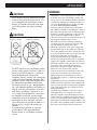
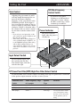
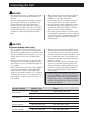
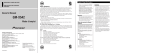
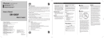
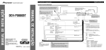
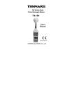
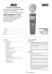
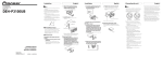
BRIDGEABLE FOUR-CHANNEL
POWER AMPLIFIER
AMPLIFICATEUR DE PUISSANCE
PONTABLE A QUATRE VOIES
Owner’s Manual
GM-6200F
Mode d’emploi
PIONEER CORPORATION
4-1, MEGURO 1-CHOME, MEGURO-KU, TOKYO 153-8654, JAPAN
PIONEER ELECTRONICS (USA) INC.
P.O. Box 1540, Long Beach, California 90801-1540, U.S.A.
TEL: (800) 421-1404
PIONEER EUROPE NV
Haven 1087, Keetberglaan 1, B-9120 Melsele, Belgium
TEL: (0) 3/570.05.11
PIONEER ELECTRONICS ASIACENTRE PTE. LTD.
253 Alexandra Road, #04-01, Singapore 159936
TEL: 65-6472-7555
PIONEER ELECTRONICS AUSTRALIA PTY. LTD.
178-184 Boundary Road, Braeside, Victoria 3195, Australia
TEL: (03) 9586-6300
PIONEER ELECTRONICS OF CANADA, INC.
300 Allstate Parkway, Markham, Ontario L3R OP2, Canada
TEL: 1-877-283-5901
PIONEER ELECTRONICS DE MEXICO, S.A. de C.V.
Blvd.Manuel Avila Camacho 138 10 piso
Col.Lomas de Chapultepec, Mexico, D.F. 11000
TEL: 55-9178-4270
<KMINX> <05I00000>
Published by Pioneer Corporation.
Copyright © 2005 by Pioneer Corporation.
All rights reserved.
Publication de Pioneer Corporation.
Copyright © 2005 Pioneer Corporation.
Tous droits de reproduction et de traduction
réservés.
Printed in China
Imprimé en Chine
<CRD4020-B/U> UC
Before Using This Product
Thank you for purchasing this PIONEER
product. It is designed to give you many
years of enjoyment.
PIONEER SUGGESTS USING A PROFESSIONAL INSTALLER DUE TO THE
COMPLEXITY OF THIS PRODUCT.
Please read all instructions and WARNINGS in this manual before attempting
operation. Should you have any questions,
contact your nearest Pioneer authorized
dealer or installation specialist.
Information to User
Alteration or modifications carried out
without appropriate authorization may
invalidate the user’s right to operate the
equipment.
Important
The serial number of this amplifier is written on the bottom of the unit. For your
own security and convenience, write it
down on the enclosed warranty card. Keep
the card handy for future reference.
After-sales service for Pioneer
products
Please contact the dealer or distributor from where
you purchased the product for its after-sales service (including warranty conditions) or any other
information. In case the necessary information is
not available, please contact the companies listed
below:
Please do not ship your product to the companies
at the addresses listed below for repair without
advance contact.
7 U.S.A.
Pioneer Electronics (USA) Inc.
CUSTOMER SUPPORT DIVISION
P.O. Box 1760
Long Beach, CA 90801-1760
800-421-1404
7 CANADA
Pioneer Electronics of Canada, Inc.
CUSTOMER SATISFACTION
DEPARTMENT
300 Allstate Parkway
Markham, Ontario L3R OP2
1-877-283-5901
For warranty information please see the Limited
Warranty sheet included with your product.
Product registration
Visit us at the following site:
1 Register your product. We will keep the details of
your purchase on file to help you refer to this
information in the event of an insurance claim
such as loss or theft.
2 Receive updates on the latest products and technologies.
3 Download owner’s manuals, order product catalogues, research new products, and much more.
<ENGLISH>
WARNING
CAUTION
Never replace the fuse with one of greater
value or rating than the original fuse. Use
of an improper fuse could result in overheating and smoke and could cause damage to the product and injury including
burns.
CAUTION
Diagram A - Proper
Diagram B - Improper
8
+ Ohm Speaker
4
+ Ohm Speaker
8
+ Ohm Speaker
4
+ Ohm Speaker
L+
R-
L+
R-
Pioneer
Amplifier
Pioneer
Amplifier
4 Ohm Bridged Mode
2 Ohm Bridged Mode
Do NOT install or use your Pioneer amplifier by wiring speakers rated at 4 Ohm (or
lower) in parallel to achieve a 2 Ohm (or
lower) bridged mode (Diagram B).
Amplifier damage, smoke, and overheating
could result from improper bridging. The
amplifier surface could also become hot to
the touch and minor burns could result.
To properly install or use a bridged mode
for a two-channel amplifier and achieve a 4
Ω load, wire two 8 Ω speakers in parallel
with Left + and Right – (Diagram A) or
use a single 4 Ω speaker. For a four-channel amplifier, follow the speaker output
connection diagram for bridging as shown
on the back of your amplifier, and wire
two 8 Ω speakers in parallel to achieve a 4
Ω load or use a single 4 Ω speaker per
channel.
If you have any questions or concerns,
please contact your local authorized
Pioneer dealer or call Pioneer customer
service.
• Handling the cord on this product or cords associated with accessories sold with the product will
expose you to lead, a chemical known to the State
of California and other governmental entities to
cause cancer and birth defects or other reproductive harm. Wash hands after handling.
• Always use the special red battery and ground
wire [RD-223], which is sold separately. Connect
the battery wire directly to the car battery positive
terminal (+) and the ground wire to the car body.
• Do not touch the amplifier with wet hands.
Otherwise you may get an electric shock. Also, do
not touch the amplifier when it is wet.
• For traffic safety and to maintain safe driving
conditions, keep the volume low enough so that
you can still hear normal traffic sound.
• Check the connections of the power supply and
speakers if the fuse of the separately sold battery
wire or the amplifier fuse blows. Detect the cause
and solve the problem, then replace the fuse with
another one of the same size and rating.
• To prevent malfunction of the amplifier and
speakers, the protective circuit will cut the power
supply to the amplifier (sound will stop) when an
abnormal condition occurs. In such a case, switch
the power to the system OFF and check the
connection of the power supply and speakers.
Detect the cause and solve the problem.
• Contact the dealer if you cannot detect the cause.
• To prevent an electric shock or short-circuit
during connection and installation, be sure to
disconnect the negative (–) terminal of the battery
beforehand.
• Confirm that no parts are behind the panel when
drilling a hole for installation of the amplifier. Be
sure to protect all cables and important equipment
such as fuel lines, brake lines and the electrical
wiring from damage.
• DO NOT allow amplifier to come into contact
with liquids due to, for example, the location
where the amplifier is installed. Electrical shock
could result. Also, amplifier and speaker damage,
smoke, and overheating could result from contact
with liquids. In addition, the amplifier surface and
the surface of any attached speakers could become
hot to the touch and minor burns could result.
Setting the Unit
<ENGLISH>
BFC (Beat Frequency
Control) Switch
Gain Control
Adjusting the gain controls A and B
will help match the output of the car
stereo to the Pioneer amplifier.
Normally, set the gain controls to the
NORMAL position. If the output is
low, even when the volume of the car
stereo is turned up, turn these controls
clockwise. If there is distortion when
the volume of the car stereo is turned
up, turn these controls counter-clockwise.
If you hear a beat while
listening to an AM broadcast
with your car stereo, change
the BFC switch using a small
standard tip screwdriver.
Power Indicator
• If you only use one input plug, set the
gain controls for speaker outputs A and
B to the same position.
• When using with an RCA equipped car
stereo (standard output of 500 mV), set
to the NORMAL position. When using
with an RCA equipped Pioneer car
stereo with max. output of 4 V or more,
adjust level to match the car stereo output level.
The power indicator
lights when the power is
switched on.
CH
A
BR
IDG
ED
SPEA
KE
R ON
PU
T
BR
IDG
ED
CH
B
Input Select Switch
For two-channel input, slide
this switch to the left. For
four-channel input, slide this
switch to the right.
LPF (Low-Pass Filter)/HPF (High-Pass Filter) Select Switch
Set the LPF/HPF select switch as follows according to the type of speaker that is connected
to the speaker output connector and the car stereo system:
LPF/HPF Select
Switch
Audio frequency range
to be output
Speaker
Type
Remarks
LPF (Left)
— 80 Hz
Subwoofer
Connect a subwoofer.
OFF (Center)
Full range
Full range
HPF (Right)
80 Hz —
Full range
Use if you want to cut the
very low frequency range
because it is not necessary
for the speakers you are
using.
Connecting the Unit
CAUTION
• Disconnect the negative (–) terminal of the battery
to avoid the risk of short-circuit and damage to
the unit.
• Secure the wiring with cable clamps or adhesive
tape. To protect the wiring, wrap adhesive tape
around it where they lie against metal parts.
• Do not route wires where they will get hot, for
example where the heater will blow over them. If
the insulation heats up, it may become damaged,
resulting in a short-circuit through the vehicle
body.
• Make sure that wires will not interfere with moving parts of the vehicle, such as the gearshift,
handbrake or seat sliding mechanism.
• Do not shorten any wires. Otherwise the protection circuit may fail to work when it should.
• Never feed power to other equipment by cutting
the insulation of the power supply wire to tap
from the wire. The current capacity of the wire
will be exceeded, causing overheating.
• Never replace the fuse with one of greater value
or rating than the original fuse. Use of an improper fuse could result in overheating and smoke and
could cause damage to the product and injury
including burns.
CAUTION:
To prevent damage and/or injury
• Do not ground the speaker wire directly or connect a negative (–) lead wire for several speakers.
• This unit is for vehicles with a 12-volt battery and
negative grounding. Before installing it in a recreational vehicle, truck or bus, check the battery
voltage.
• If the car stereo is kept on for a long time while
the engine is at rest or idling, the battery may go
dead. Turn the car stereo off when the engine is at
rest or idling.
• If the system remote control wire of the amplifier
is connected to the power terminal through the
ignition switch (12 V DC), the amplifier will
always be on when the ignition is on— regardless
of whether the car stereo is on or off. Because of
this, the battery could go dead if the engine is at
rest or idling.
Speaker Channel
• Speakers to be connected to the amplifier should
conform with the standards listed below. If they
do not conform, they may catch fire, emit smoke
or become damaged. The speaker impedance must
be 2 to 8 ohms. But in case of two-channel and
other bridge connections, the speaker impedance
must be 4 to 8 ohms.
• Install and route the separately sold battery wire
as far away as possible from the speaker wires.
Install and route the separately sold battery wire,
ground wire, speaker wires and the amplifier as
far away as possible from the antenna, antenna
cable and tuner.
• Cords for this product and those for other products may be different colors even if they have the
same function. When connecting this product to
another product, refer to the supplied Installation
manuals of both products and connect cords that
have the same function.
Speaker Type
Power
Subwoofer
Nominal input: Min. 70 W
Other than subwoofer
Max. input: Min. 120 W
Subwoofer
Nominal input: Min. 200 W
Other than subwoofer
Max. input: Min. 300 W
Three-channel
Subwoofer
Nominal input: Min. 70 W
Speaker output A
Other than subwoofer
Max. input: Min. 120 W
Three-channel
Subwoofer
Nominal input: Min. 200 W
Speaker output B
Other than subwoofer
Max. input: Min. 300 W
Four-channel
Two-channel
Connection Diagram
Fuse (30 A)
Special red battery wire [RD-223] (sold separately)
After making all other connections at the amplifier,
connect the battery wire terminal of the amplifier to
the positive (+) terminal of the battery.
Grommet
Fuse (30 A)
Ground wire (black) [RD-223] (sold separately)
Connect to metal body or chassis.
Connecting wire with RCA
pin plugs (sold separately).
Car stereo with
RCA output jacks
External Output
If only one input plug is used,
do not connect anything to
RCA input jack B.
RCA input
Amplifier with
RCA input jacks
Input Select Switch
For two-channel input, slide this
switch to the left. For four-channel
input, slide this switch to the right.
Speaker input terminal
See the “Using the Speaker Input”
section.
Front side
RCA output jack
RCA input jack B
RCA input jack A
Back side
Connecting wire with RCA pin
plugs (sold separately).
Fuse (25 A) × 2
Speaker output terminal
See the “Connecting the
Speakers and Input Wires”
section for speaker
connection instructions.
System remote control wire (sold separately)
Connect the male terminal of this wire to the system remote control
terminal of the car stereo (SYSTEM REMOTE CONTROL). The
female terminal can be connected to the auto-antenna relay control
terminal. If the car stereo does not have a system remote control terminal, connect the male terminal to the power terminal through the
ignition switch.
<ENGLISH>
Connecting the Power Terminal
WARNING
• Always use the special red battery and ground
wire [RD-223], which is sold separately. Connect
the battery wire directly to the car battery positive
terminal (+) and the ground wire to the car body.
Failure to securely fasten the battery wire to the terminal using the terminal screws could cause the terminal area to overheat and could result in damage
and injury including minor burns.
1. Pass the battery wire from the
engine compartment to the interior
of the vehicle.
Connecting the Speaker Output
Terminals
• After making all other connections to the
amplifier, connect the battery wire terminal of
the amplifier to the positive (+) terminal of
the battery.
Engine
Fuse (30 A) compart- Interior of
the vehicle
ment
1. Expose the end of the speaker wires
using nippers or a cutter by about
10 mm (3/8 inch) and twist.
2. Attach lugs to speaker wire ends.
Lugs not supplied.
• Use pliers, etc., to crimp lugs to wires.
Fuse (30 A)
Positive terminal
Insert the O-ring rubber
grommet into the vehicle
body.
Drill a 14 mm
(1/2 inch) hole
into the vehicle
body.
3. Connect the speaker wires to the
speaker output terminals.
• Fix the speaker wires securely with the terminal screws.
Terminal screw
2. Twist the battery wire, ground wire
and system remote control wire.
3. Attach lugs to wire ends. Lugs not
supplied.
• Use pliers, etc., to crimp lugs to wires.
Speaker
output
terminal
4. Connect the wires to the terminal.
• Fix the wires securely with the terminal
screws.
GND terminal
Power terminal
System remote
control terminal
System remote
control wire
Ground wire
Battery wire
Speaker wire
Connecting the Unit
Using the Speaker Input
Connect the car stereo speaker output wires to the amplifier using the supplied speaker input
connector.
• Do not connect both the RCA input and the speaker input at the same time.
7 Connections when using the speaker input
Green: CH B, Left +
Green/black: CH B, Left ≠
Violet/black: CH B, Right ≠
Violet: CH B, Right +
Gray: CH A, Right +
Car Stereo
Gray/black: CH A, Right ≠
Speaker input connector
To speaker input terminal of this unit.
Speaker output
White/black: CH A, Left ≠
White: CH A, Left +
<ENGLISH>
Speaker (Left)
Two-channel mode (Mono)
Speaker (Mono)
(Right)
Speaker out A
(Left)
≠
+
+≠ ≠ +
Three-channel mode
(Right)
Speaker out A
(Left)
+≠ ≠ +
≠
Speaker out B
(Mono)
≠
+≠ ≠ +
(Left)
Speaker out B
(Right)
+
Four-channel mode
Speaker (Right)
+≠
The speaker output mode can be fourchannel, three-channel (stereo + mono) or
two-channel (stereo, mono). Connect the
speaker leads to suit the mode according to
the figures shown below.
• In the case of four-channel or threechannel mode, if only one input plug is
used, such as when the car stereo has
only one output (RCA output), connect
the plug to RCA input jack A, but do not
connect a plug to RCA input jack B.
• In the case of two-channel mode connect
RCA plugs to the RCA input jack A.
Two-channel mode (Stereo)
≠+
Connecting the Speakers and Input
Wires
Speaker (Mono)
+
Installation
CAUTION
• Do not install in:
—Places where it could injure the driver or passengers if the vehicle stops suddenly.
—Places where it may interfere with the driver,
such as on the floor in front of the driver’s
seat.
• Make sure that wires are not caught in the sliding
mechanism of the seats, resulting in a short-circuit.
• Confirm that no parts are behind the panel when
drilling a hole for installation of the amplifier.
Protect all cables and important equipment such
as fuel lines, brake lines and electrical wiring
from damage.
• Install tapping screws in such a way that the
screw tip does not touch any wire. This is important to prevent wires from being cut by vibration
of the car, which can result in fire.
• DO NOT allow amplifier to come into contact
with liquids due to, for example, the location
where the amplifier is installed. Electrical shock
could result. Also, amplifier and speaker damage,
smoke, and overheating could result from contact
with liquids. In addition, the amplifier surface and
the surface of any attached speakers could become
hot to the touch and minor burns could result.
• To ensure proper installation, use the supplied
parts in the manner specified. If any parts other
than the supplied ones are used, they may damage
internal parts of the amplifier, or they may
become loose causing the amplifier to shut down.
• Never replace the fuse with one of greater value
or rating than the original fuse. Use of an improper fuse could result in overheating and smoke and
could cause damage to the product and injury
including burns.
<ENGLISH>
• Do not install the amplifier on unstable places
such as the spare tire board.
• The best location for installation differs with the
car model and installation location. Secure the
amplifier at a sufficiently rigid location.
• Make temporary connections first and check that
the amplifier and the system operate properly.
• After installing the amplifier, confirm that the
spare tire, jack and tools can be easily removed.
Example of installation on the floor
mat or on the chassis
1. Place the amplifier where it is to be
installed. Insert the supplied tapping
screws (4 × 18 mm) into the screw
holes. Push on the screws with a
screwdriver so they make marks
where the installation holes are to be
located.
2. Drill 2.5 mm (1/8 inch) diameter
holes at the point marked, and
install the amplifier, either on the
carpet or directly to the chassis.
Tapping-screws
(4 × 18 mm)
CAUTION:
To prevent malfunction and/or injury
• To ensure proper heat dissipation of the amplifier,
be sure of the following during installation.
—Allow adequate space above the amplifier for
proper ventilation.
—Do not cover the amplifier with a floor mat or
carpet.
• DO NOT allow amplifier to come into contact
with liquids due to, for example, the location
where the amplifier is installed. Electrical shock
could result. Also, amplifier and speaker damage,
smoke, and overheating could result from contact
with liquids. In addition, the amplifier surface and
the surface of any attached speakers could become
hot to the touch and minor burns could result.
Drill a 2.5 mm (1/8 inch)
diameter hole
Floor mat
or chassis
Specifications
<ENGLISH>
Power source .............................................................................................................. 14.4 V DC (10.8 — 15.1 V allowable)
Grounding system ............................................................................................................................................ Negative type
Current consumption ...................................................................................................... 35.0 A (at continuous power, 4 Ω)
Average current drawn* .......................................................................................................... 9.0 A (4 Ω for four channels)
15.0 A (4 Ω for two channels)
Fuse .......................................................................................................................................................................... 25 A × 2
Dimensions ........................................................................................................................ 300 (W) × 61 (H) × 336 (D) mm
[12 in. (W) × 2-3/8 in. (H) × 1 ft. 1 in. (D)]
Weight ........................................................................................................ 3.9 kg (8.6 lbs.) (Leads for wiring not included)
Maximum power output .............................................................................................. 120 W × 4 ( 4 Ω) / 300 W × 2 ( 4 Ω)
Continuous power output ............................................................ 60 W × 4 (at 14.4 V, 4 Ω, 20 Hz — 20 kHz 0.2% THD)
150 W × 2 (at 14.4 V, 4 Ω, 20 Hz — 20 kHz 0.8% THD)
75 W × 4 (at 14.4 V, 2 Ω, 20 Hz — 20 kHz 0.8% THD)
Load impedance ............................................................................................................................ 4 Ω (2 — 8 Ω allowable)
(Bridge connection: 4 — 8 Ω allowable)
Frequency response .......................................................................................................... 10 Hz — 50 kHz (+0 dB, –1 dB)
Signal-to-noise ratio ........................................................................................................................ 95 dB (IHF-A network)
Distortion ............................................................................................................................................ 0.01 % (10 W, 1 kHz)
Separation ........................................................................................................................................................ 70 dB (1 kHz)
Low pass filter ................................................................................................................................ Cut off frequency: 80 Hz
Cut off slope: –12 dB/oct
High pass filter ................................................................................................................................ Cut off frequency: 80 Hz
Cut off slope: –12 dB/oct
Gain control ...................................................................................................................................... RCA: 400 mV — 6.5 V
Speaker: 1.6 — 26 V
Maximum input level / impedance ........................................................................................................ RCA: 6.5 V / 22 kΩ
Speaker: 26 V / 40 kΩ
Power output ........................................................................................ 60 W RMS × 4 channels
(4 Ω and 1 % THD+N)
150 W RMS × 2 channels
(4 Ω and 1 % THD+N)
75 W RMS × 4 channels
(2 Ω and 1 % THD+N)
Signal-to-noise ratio ............................................................ 80 dBA (Reference: 1 W into 4 Ω)
Note:
• Specifications and the design are subject to possible modification without notice
due to improvements.
*Average current drawn
• The average current drawn is nearly the maximum current drawn by this unit
when an audio signal is input. Use this value when working out total current
drawn by multiple power amplifiers.
Additional information
<English>
• This unit is equipped with a protective function to prevent
malfunction of the unit itself and speakers from too much
output, improper use or improper connection.
• When outputting sound at high volume etc., this function
will cut off the sound output in a few seconds. But this is
not a malfunction. When you turn down the volume of the
head unit the sound output will be restored.
• If sound output is cut, the gain control of this unit may be
improperly set. To ensure continuous sound output at
increased volume of the head unit, set the gain control of
the amplifier to a proper position according to the preout
maximum output level of the head unit (Fig. 1). There is no
need to decrease the volume of the head unit and too
much output is controlled (Fig. 2, Fig. 3).
• If you decrease the volume of the head unit and set the
gain control of the amplifier to the proper position but still
the sound cuts out from time to time, contact the nearest
authorized PIONEER Service Station.
Power
Power
Maximum gain
Normal gain
Equal power
Head unit volume steps
Head unit volume steps
Amplifier gain
Amplifier gain
(normal)
(maximum)
If you raise the gain of the amplifier to an improper level, only
distortion is increased and the power increases only slightly.
Fig. 2 Relationship between the gain of the amplifier and
the output power of the head unit
Normal gain
Maximum gain
Equal power
Preout level: 6.5 V
Preout level: 4 V
Signal
waveform
Preout level: 2 V
Fig. 1 Gain control of this unit
Signal
waveform
Amplifier gain
Amplifier gain
(normal)
(maximum)
With high output the signal waveform is distorted, if you raise the
gain of the amplifier the power changes only slightly.
Fig. 3 Signal waveform when outputting at high volume
by the gain control of the amplifier
<KMINX> <CRP1337-A/U>