1
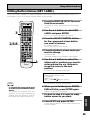
AUDIO/VIDEO MULTI-CHANNEL
RECEIVER
VSX-45TX
Operating Instructions
Thank you for buying this Pioneer product.
Please read through these operating instructions
so you will know how to operate your model
properly. After you have finished reading the
instructions, put them away in a safe place for
future reference.
IMPORTANT NOTICE
H006AEn
The serial number for this equipment is located in the
rear panel. Please write this serial number on your
enclosed warranty card and keep it in a secure area. This
is for your security.
2
3
Table of Contents
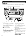
Displays & Controls ............................ 28
Before You Start .................................... 7
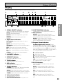
Front Panel ................................................................. 28
Remote Control .......................................................... 30
Display ........................................................................ 33
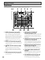
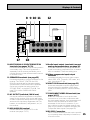
Back Panel .................................................................. 34
Easy Setup Guide Part 1 ....................... 9
1 Auto Surround Sound Setup ............................... 13
2 Playing a DVD with Surround Sound ................. 15
Connecting Your Equipment .............. 16
Stereo and Multichannel Playback ........................... 44
Switching ANALOG/DIGITAL Signal Input ......... 45
Listening Modes ........................................................ 46
STEREO modes ..................................................... 46
MOVIE modes (SURROUND mode) .................... 47
MUSIC modes (SURROUND mode) .................... 48
Adjusting the Effect of a Listening Modes ......... 49
Adding/Adjusting the Effect in
Dolby Pro Logic II Music Mode ........................... 49
Listening with Acoustic Calibration EQ ................... 50
Reducing Noise During Playback
(DIGITAL NR Function) .............................................. 50
Listening in MIDNIGHT Mode ................................... 51
Listening in LOUDNESS Mode ................................. 51
Adjusting Bass and Treble (TONE CONTROL) ........ 52
Listening in HI-BIT/SAMPLING mode ...................... 53
DVD-Audio/MULTI CHANNEL IN Playback .............. 53
SB CH MODE button .................................................. 54
SB CH MODE ......................................................... 54
VIRTUAL SURROUND BACK Mode ..................... 54
DUAL MONO setting and Playback .......................... 55
Using Headphones .................................................... 55
Video Select ............................................................... 56
Adjusting the Brightness of the Display
(DIMMER) ................................................................... 56
Using Other Functions ........................ 69
Recording from Audio/Video Components ............. 69
SECOND ZONE (Speaker System B) Setup ............. 70
Stereo playback in another room ........................ 70
A/B Speaker Button .............................................. 70
Setting up and Using the USB Audio Connection .... 71
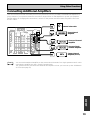
Connecting Additional Amplifiers ............................ 73
MULTI ROOM ............................................................. 74
MULTI ROOM connections with an IR receiver ... 74
MULTI ROOM setup ............................................. 76
Controlling the MULTI ROOM system from the
main room ............................................................. 77
Controlling the MULTI ROOM system from the
sub room ............................................................... 78
The PIONEER SR System: Operating other PIONEER
components ............................................................... 79
Multi Operations ........................................................ 80
Performing multi operations ............................... 81
SYSTEM OFF .............................................................. 82
Using SYSTEM OFF .............................................. 83
Editing Remote Control Display Names .................. 84
Editing Buttons Names (KEY LABEL) ....................... 85
Adjusting the Light on the Remote Control ............. 86
Clearing Remote Control Settings You Have Input .. 87
Resetting the Main Unit ............................................ 88
Techno Tidbits & Problem-solving ... 105
Dolby ......................................................................... 105
Dolby Digital ....................................................... 105
Dolby Pro Logic II ............................................... 105
Dolby Digital Surround EX ................................ 106
DTS ........................................................................... 106
DTS ...................................................................... 106
DTS-ES ................................................................ 106
DTS Neo:6 ........................................................... 106
DTS 96/24 ............................................................ 106
THX ........................................................................... 107
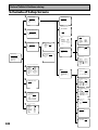
Schemata of Setup Screens .................................... 108
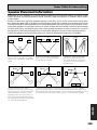
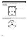
Speaker Placement Information ............................. 109
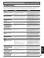
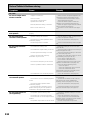
Troubleshooting ....................................................... 111
Preset Code Brands ................................................. 116
Specifications ........................................................... 119
BASIC
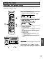
Using the Tuner ................................... 57
Automatic and Manual Tuning ................................. 57
MPX Mode ............................................................ 57
Direct Access Tuning ................................................. 58
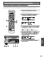
Memorizing Frequently Used Stations .................... 59
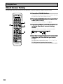
Naming Memorized Stations .................................... 60
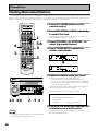
Recalling Memorized Stations .................................. 61
EXPERT
Connecting your TV ................................................... 16
Component Video Input Default Settings ........... 16
Connecting Video Components ................................ 17
Connecting a DVD player ..................................... 17
Connecting VCRs or DVRs ................................... 18
Connecting a Video Component
to the Front Panel ................................................. 18
Connecting Satellite TV(SAT) Components ........ 19
Connecting Analog Audio Components .................. 20
Connecting to the Multi Channel Analog Inputs
(DVD-Audio or Super Audio CD (SACD) compatible
player) ...................................................................... 21
Connecting Digital Audio Components ................... 22
Digital Input Default Settings .............................. 23
Connecting the Radio Antennas ............................... 24
Using outdoor antennas ...................................... 24
Connecting Speakers ................................................. 25
Speaker impedance .............................................. 26
Bi-wiring your speakers ....................................... 26
Placing Your Speakers ............................................... 27
Speaker placement ............................................... 27
AC Power Cord ........................................................... 27
AC Outlet [switched 100W max] ............................... 27
Basic Operation ................................... 44
Other System Settings .............................................. 89
THX CINEMA Setup ................................................... 90
Assigning the Digital Inputs ...................................... 91
Assigning the Component Video Inputs .................. 92
FUNCTION RENAME ................................................. 93
PHONO/LINE Setup ................................................... 94
12V TRIGGER ............................................................. 95
Expert Setup ............................................................... 96
CROSSOVER NETWORK ...................................... 97
FINE CHANNEL LEVEL ......................................... 98
FINE CHANNEL DELAY ........................................ 99
ACOUSTIC CAL EQ ............................................. 100
BASS PEAK LEVEL ............................................. 103
DYNAMIC RANGE CONTROL ............................ 104
SURROUND SETUP
Easy Setup Guide Part 2 ..................... 13
SURRBACK SYSTEM (Surround Back System) ...... 37
QUICK setup ............................................................... 38
NORMAL setup .......................................................... 39
SPEAKER SETTING .............................................. 40
CHANNEL LEVEL (channel balance) ................... 42
CHANNEL DELAY ................................................. 43
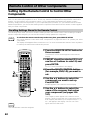
Setting Up the Remote Control to Control Other
Components ............................................................... 62
Recalling Settings Stored in the
Remote Control ..................................................... 62
Programming Signals from Other Remote
Controls (LEARNING Mode) ................................ 64
Using Remote Control with Other Components ..... 66
CD/MD/CD-R/VCR/DVD/LD/DVD Recorder/
Cassette Deck operations ..................................... 66
Cable TV/Satellite TV/ Digital TV/ TV operations
............................................................................... 67
Setting up the DIRECT FUNCTION ........................... 68
Fine Tuning Your System ................... 89
PREPARATION
Home Theater: The Basics .......................................... 9
1) Your Home System ............................................ 9
2) The Source Material ........................................... 9
3) The Listening Modes .......................................... 9
Conclusion .............................................................. 9
1 Hooking Up Your DVD Player & TV ..................... 10
Digital Connections .............................................. 10
2 Speaker Connections ........................................... 11
3 Setting up the Main Unit ...................................... 12
4 Assigning the Digital Inputs ................................ 12
Setting Up for Surround Sound ........ 36
Remote Control of Other
Components ........................................ 62
GUIDE
EASY SETUP
PREPARATION
Features ................................................. 6
Checking the Supplied Accessories ........................... 7
Preparing the Remote Control .................................... 7
Loading the batteries ............................................. 7
Remote Control Battery Indicator ......................... 7
Operating range of remote control unit ............... 8
Installing the Receiver ................................................. 8
Opening the Front Panel ............................................. 8
4
Table of Contents
5
Table of Contents
Displays & Controls ............................ 28
Before You Start .................................... 7
Front Panel ................................................................. 28
Remote Control .......................................................... 30
Display ........................................................................ 33
Back Panel .................................................................. 34
Easy Setup Guide Part 1 ....................... 9
1 Auto Surround Sound Setup ............................... 13
2 Playing a DVD with Surround Sound ................. 15
Connecting Your Equipment .............. 16
Stereo and Multichannel Playback ........................... 44
Switching ANALOG/DIGITAL Signal Input ......... 45
Listening Modes ........................................................ 46
STEREO modes ..................................................... 46
MOVIE modes (SURROUND mode) .................... 47
MUSIC modes (SURROUND mode) .................... 48
Adjusting the Effect of a Listening Modes ......... 49
Adding/Adjusting the Effect in
Dolby Pro Logic II Music Mode ........................... 49
Listening with Acoustic Calibration EQ ................... 50
Reducing Noise During Playback
(DIGITAL NR Function) .............................................. 50
Listening in MIDNIGHT Mode ................................... 51
Listening in LOUDNESS Mode ................................. 51
Adjusting Bass and Treble (TONE CONTROL) ........ 52
Listening in HI-BIT/SAMPLING mode ...................... 53
DVD-Audio/MULTI CHANNEL IN Playback .............. 53
SB CH MODE button .................................................. 54
SB CH MODE ......................................................... 54
VIRTUAL SURROUND BACK Mode ..................... 54
DUAL MONO setting and Playback .......................... 55
Using Headphones .................................................... 55
Video Select ............................................................... 56
Adjusting the Brightness of the Display
(DIMMER) ................................................................... 56
Using Other Functions ........................ 69
Recording from Audio/Video Components ............. 69
SECOND ZONE (Speaker System B) Setup ............. 70
Stereo playback in another room ........................ 70
A/B Speaker Button .............................................. 70
Setting up and Using the USB Audio Connection .... 71
Connecting Additional Amplifiers ............................ 73
MULTI ROOM ............................................................. 74
MULTI ROOM connections with an IR receiver ... 74
MULTI ROOM setup ............................................. 76
Controlling the MULTI ROOM system from the
main room ............................................................. 77
Controlling the MULTI ROOM system from the
sub room ............................................................... 78
The PIONEER SR System: Operating other PIONEER
components ............................................................... 79
Multi Operations ........................................................ 80
Performing multi operations ............................... 81
SYSTEM OFF .............................................................. 82
Using SYSTEM OFF .............................................. 83
Editing Remote Control Display Names .................. 84
Editing Buttons Names (KEY LABEL) ....................... 85
Adjusting the Light on the Remote Control ............. 86
Clearing Remote Control Settings You Have Input .. 87
Resetting the Main Unit ............................................ 88
Techno Tidbits & Problem-solving ... 105
Dolby ......................................................................... 105
Dolby Digital ....................................................... 105
Dolby Pro Logic II ............................................... 105
Dolby Digital Surround EX ................................ 106
DTS ........................................................................... 106
DTS ...................................................................... 106
DTS-ES ................................................................ 106
DTS Neo:6 ........................................................... 106
DTS 96/24 ............................................................ 106
THX ........................................................................... 107
Schemata of Setup Screens .................................... 108
Speaker Placement Information ............................. 109
Troubleshooting ....................................................... 111
Preset Code Brands ................................................. 116
Specifications ........................................................... 119
BASIC
Using the Tuner ................................... 57
Automatic and Manual Tuning ................................. 57
MPX Mode ............................................................ 57
Direct Access Tuning ................................................. 58
Memorizing Frequently Used Stations .................... 59
Naming Memorized Stations .................................... 60
Recalling Memorized Stations .................................. 61
EXPERT
Connecting your TV ................................................... 16
Component Video Input Default Settings ........... 16
Connecting Video Components ................................ 17
Connecting a DVD player ..................................... 17
Connecting VCRs or DVRs ................................... 18
Connecting a Video Component
to the Front Panel ................................................. 18
Connecting Satellite TV(SAT) Components ........ 19
Connecting Analog Audio Components .................. 20
Connecting to the Multi Channel Analog Inputs
(DVD-Audio or Super Audio CD (SACD) compatible
player) ...................................................................... 21
Connecting Digital Audio Components ................... 22
Digital Input Default Settings .............................. 23
Connecting the Radio Antennas ............................... 24
Using outdoor antennas ...................................... 24
Connecting Speakers ................................................. 25
Speaker impedance .............................................. 26
Bi-wiring your speakers ....................................... 26
Placing Your Speakers ............................................... 27
Speaker placement ............................................... 27
AC Power Cord ........................................................... 27
AC Outlet [switched 100W max] ............................... 27
Basic Operation ................................... 44
Other System Settings .............................................. 89
THX CINEMA Setup ................................................... 90
Assigning the Digital Inputs ...................................... 91
Assigning the Component Video Inputs .................. 92
FUNCTION RENAME ................................................. 93
PHONO/LINE Setup ................................................... 94
12V TRIGGER ............................................................. 95
Expert Setup ............................................................... 96
CROSSOVER NETWORK ...................................... 97
FINE CHANNEL LEVEL ......................................... 98
FINE CHANNEL DELAY ........................................ 99
ACOUSTIC CAL EQ ............................................. 100
BASS PEAK LEVEL ............................................. 103
DYNAMIC RANGE CONTROL ............................ 104
SURROUND SETUP
Easy Setup Guide Part 2 ..................... 13
SURRBACK SYSTEM (Surround Back System) ...... 37
QUICK setup ............................................................... 38
NORMAL setup .......................................................... 39
SPEAKER SETTING .............................................. 40
CHANNEL LEVEL (channel balance) ................... 42
CHANNEL DELAY ................................................. 43
Setting Up the Remote Control to Control Other
Components ............................................................... 62
Recalling Settings Stored in the
Remote Control ..................................................... 62
Programming Signals from Other Remote
Controls (LEARNING Mode) ................................ 64
Using Remote Control with Other Components ..... 66
CD/MD/CD-R/VCR/DVD/LD/DVD Recorder/
Cassette Deck operations ..................................... 66
Cable TV/Satellite TV/ Digital TV/ TV operations
............................................................................... 67
Setting up the DIRECT FUNCTION ........................... 68
Fine Tuning Your System ................... 89
PREPARATION
Home Theater: The Basics .......................................... 9
1) Your Home System ............................................ 9
2) The Source Material ........................................... 9
3) The Listening Modes .......................................... 9
Conclusion .............................................................. 9
1 Hooking Up Your DVD Player & TV ..................... 10
Digital Connections .............................................. 10
2 Speaker Connections ........................................... 11
3 Setting up the Main Unit ...................................... 12
4 Assigning the Digital Inputs ................................ 12
Setting Up for Surround Sound ........ 36
Remote Control of Other
Components ........................................ 62
GUIDE
EASY SETUP
PREPARATION
Features ................................................. 6
Checking the Supplied Accessories ........................... 7
Preparing the Remote Control .................................... 7
Loading the batteries ............................................. 7
Remote Control Battery Indicator ......................... 7
Operating range of remote control unit ............... 8
Installing the Receiver ................................................. 8
Opening the Front Panel ............................................. 8
4
Table of Contents
5
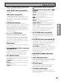
Features
High Quality, Balanced Multichannel Design
The VSX-45TX receiver is constructed with Pioneer’s industry-leading advanced and well balanced multichannel
concept. This means it is designed to reproduce music and movie soundtracks as close as possible to the
intentions of the producer during mastering. The receiver uses a revolutionary 3-D Frame Construction
technique and a Symmetrical Power Train Design, with high-performance Advanced Direct Energy MOS-FET
output devices, generating 100 watts of power for 7 independent channels.
Multichannel Acoustic Calibration EQ System (MCACC)
In order to make setting up as easy as possible for users we have created the MCACC system. This unique and
convenient way of getting good surround sound from the receiver makes trouble-free set up a snap. With the
microphone equipped remote control plugged into the front panel with the remote control cable the MCACC
system creates a monitoring environment to establish the parameters of the sound for the specific room you are
using. The MCACC system adjusts the parameters to establish excellent surround sound effects and offer you
the best in home theater for the minimum of effort.
Dolby Digital EX, DTS-ES, DTS 96/24 and the Latest Audio and Video
Formats
The VSX-45TX is equipped with Dolby Digital EX decoding, the very latest Dolby Digital contribution to home
theater with surround back speakers in addition to surround speakers. These additional speakers make home
theater even more realistic and powerful. Naturally, you can also play all existing audio formats, including the
recently developed Dolby Pro Logic II and DTS-ES Extended Surround formats on the VSX-45TX as well. On the
video side, the component video output is fully compatible with high definition, progressive-scan digital video
(720p).
Lucasfilm and THX are trademarks or registered
trademarks of Lucasfilm, Ltd. & TM. Surround EX
is a jointly developed technology of THX and Dolby
Laboratories, and is a trademark of Dolby
Laboratories. All rights reserved. Used under
authorization.
Manufactured under license from Dolby Laboratories.
“Dolby”, “Pro Logic”, “Surround EX” and double-D
symbol are trademarks of Dolby Laboratories.
"DTS", "DTS-ES Extended Surround" and "Neo:6" are
trademarks of Digital Theater Systems, Inc.
Universal Player Compatibility (DVD Audio/Super Audio CD [SACD])
This receiver incorporates the latest technology and is able to handle cutting edge audio formats, like DVD Audio
and Super Audio CD (SACD) which are just hitting the market. Its high compatibility offers a variety of inputs to
decode all types of sources at the highest possible quality. The receiver’s multichannel input connections lets you
hook up eight discrete channels of audio.
12V Trigger and USB Audio Hooks ups
For extra convenience the 12V Trigger is a connection method that enables external components to turn on
automatically when the VSX-45TX is switched on. The USB Audio port is a future-oriented connector that allows
you to hook a USB-compatible PC to the receiver.
Audio Scaler (HI BIT/HI SAMPLING)
This new technology enables the user to hear CD and DVD, as well as other soundtracks at a wider dynamic
range, allowing for finer audio reproduction. This Audio Scaler approximates the audio of high end formats just
becoming available now.
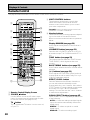
LCD Illuminated Remote Control and Urushi Lacquer Aluminum Panel
This self-illuminating remote control simplifies operation even in a darkened home theater room. Preset codes
for other equipment and a learning function make it possible to use the remote control to operate products from
other manufacturers. The full range of receiver functions can be controlled using the remote. The smooth finish
and left-right symmetry of the urushi lacquer aluminum panel is emblematic of the high quality of the
equipment.
The Energy-saving Design
6
This unit is designed to use 0.8 W of energy when the receiver is in standby mode.
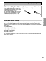
Before You Start
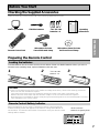
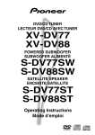
Checking the Supplied Accessories
Please check that you have received all of the following supplied accessories.
VSX-45TX
AM Loop Antenna
FM Wire Antenna
“AA” IEC LR6
batteries x 4
Operating
Instructions
Operating Instructions
P
TU
SE
CE
R
U
S0
TV
LT
LD
D/ MU
DV
2
R
VC
SY
STE
VER
EI
EC
R
FF
O
M
TV
2
R
/C
7
E
BL
RE
L
+10
DE
MO
IDE
FF
8
/O
NU
V ON
RN
CO
CH
AN
DN
MI
T
IGH
E
ND
E
UT
M
OU
R
RR
SU
TE
EN
IC
ST
OU
AC EQ
M
LU
VO
IC
I CH
LT T
PU
MU IN
/
EO T
ER EC
ST DIR
E
OD
US
M
M
¢NEL+
H
T
C
PU
IN
L
AT
RO
ST
NT
TV
IE
OV
M
¡ ION +
T
PU
IN
S
AS
CL
7
TV
TV
L
VO
E
MOD LE
DISP B TIT +
SU NG
NI
TU
TU
3
RE
IT
EX
U
EN
VM
DT
ND
BA
4NEL –
P ME K
TO
AC
TR
DT
–
C
R
DIS
CH
AR
SE GU
R
NG
TE
EN
TE
EN
NI
TU
¶
AT
ST
1 ION –
AN
CH
TV
E
MOT
RE SETU
CH
SB DE
MO
P
Î
Remote Control Unit
Microphone for Auto
Surround Sound Setup
Microphone Stand for Auto
Surround Sound Setup
PREPARATION
MPX
+ 8
–
SE
O
DI
SS
CE
T AC
EC
DIR
AU
4
H
IT
ED
CT
FE
/T
IVE
U
0
P
EF
CE
3
RE
SS
BA
T
R
NE
TU
EN
TU
SE
HI-BI
M
EM
6
ST
LTI ION
AT
MU
ER
OP
R
DN
SY
9
L
SE
ER
N
TU
NE
TO
SS
NT
CO
NE
EO
VID
5
UD
D
C
LO
D/ 2
M PE
TA
L
L
L SE
NA
SIG
1
MER
/
R1 R
VC DV
/
-R 1
CD PE
TA
DIM
O
AT
/S NTR
TV
O
I C EO
VID
PREPARATION
AUDIO/VIDEO MULTI-CHANNEL
RECEIVER
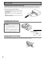
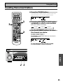
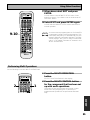
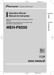
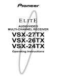
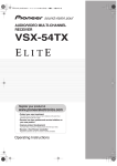
Preparing the Remote Control
Loading the batteries
Load the batteries into the remote control as shown below. Please use alkaline batteries. When you notice a
decrease in the operating range, replace all batteries with new ones.
1
2
“AA” IEC LR6
3
batteries x 4
CAUTION!
Incorrect use of batteries may result in such hazards as leakage and bursting. Observe the following precautions.
• Never use new and old batteries together.
• Insert the plus and minus sides of the batteries properly according to the marks in the battery case.
• Batteries with the same shape may have different voltages. Do not use different batteries together.
• When disposing of used batteries, please comply with governmental regulations or environmental public institution’s
rules that apply in your country or area.
Remote Control Battery Indicator
When the batteries get too weak to operate the remote control properly an
indicator warning screen will appear on the remote. Change the batteries as
shown above. This must be done within five minutes or all your remote control
settings will be cleared.
Shows when the
batteries are getting weak
SETUP
7
Before You Start
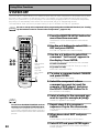
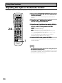
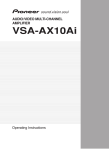
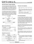
Operating range of remote control unit
The area in which you can use the remote control to operate the VSX-45TX is fairly large. To use, point the
remote control toward the remote sensor on the front panel of this unit while within the range shown below.
Remote control may not function properly if:
• There are obstacles between the remote control and
the remote sensor.
• Direct sunlight or fluorescent light is shining onto the
remote sensor.
• The receiver located near a device emitting infrared
rays.
• Operated simultaneously with another remote control
which uses infrared rays.
30
30
S0
SET
CE
UR
UP
TV
EM
DIM
F
OF
CD
ST
SY
VCRDVR
AM
T
VIDE
1
SA
MER
5
SEL
INP
O
P
AM
A/B
L
EO
R
RO VID
L
AKE
TV NT
R
SEL
SPE 4
NE
CO
/CH
I
SS
C
TU
R2
ECT 8
LT
DNE
DIS
VC
/LD
EFF
LOU 3
MU
+
R/
2
DVD
E1
E
CD1/
12 MODE UP
TAP
TAP
ATT
SET
10
UT
AL
T
CON
SIGN
2
E
TON
TV
6
S/T
LE
DIR
ECT
MPX
TER
EN
STA
RF
CHA
+
STA
CHA
NNE
¢L
TION
+
IC
AV
ING
TEN DE
LIS MO
MULINPU
T
REO
REC
STE
/DI
(DV
ME
LU
VO
ITAL
UST
DIG NR
DARD
ACO CAL
STAN
IGHT
NCED
MA
MIDN
ND NCED
D)
CERT
ROU ADVACON SAC
CH
D-A/ TI T
SUR
ADVACINE
UT
CH
INP
X
TH
TV
¡ +
ING
U
MEN
T
L
TRO
CON
TUN
A
EXTR
URN
RET
EXIT
INPU
TV
7
SS
TV
L
VO
CLA
TV
3
D
–
BAN
NNE
8
4L
TION
ATT
1 –
ING
7 +
DISP OTE
–
REM
11 ACCESS
0
P
GU
TUS
STA IDE
10
REB
TI N
SEL
MUL ATIO
BAS
OPER
9 UP
SET
TEM NU
SYS ME
TUN
¶ –
23 feet (7m)
NINGCT
TE
HT
LIG
ING
RN
Î
LEA
D
IT
AN UN
D
L
ME TRO
0
AM
CON
729
OGR
OTE
-PR
AXD
REM
LISTE SELE
CH
MU
PRE
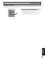
Installing the Receiver
CAUTION!
• Do not cover this unit in any way, for example with a sheet or piece of cloth. This would
prevent proper heat dispersal.
• Do not any place object directly on top of
this unit. This also would prevent proper heat
dispersal.
• Be sure to leave adequate ventilation space
around the amp! When installing in a rack,
shelf, etc., be sure to leave more than 8
inches of space above the receiver.
8 inches (20 cm)
Receiver
Opening the Front Panel
To open the front panel push gently on the lower third of the panel with your finger.
8
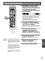
Easy Setup Guide Part1
1) Your Home System
The heart of your system is the VSX-45TX receiver and it is very flexible in getting you theater-like surround sound. You
can use this receiver with anywhere from two to seven speakers (front left, front right, center, surround left and right,
and surround back left and right) and a subwoofer to get home theater surround sound. We recommend you use seven
speakers and a subwoofer. If this is not possible follow the instructions in "Auto Surround Setup" in the "Easy Setup
Guide Part 2" and you will still be able to get good surround sound. Also, a DVD player is essential for home theater and
you can also hook up satellite or cable TV tuner to this receiver and get a more home theater-like sound from these
sources.
PREPARATION
Most consumers are used to using stereo equipment to listen to music but many people are not used to home theater
systems that give you many more options when listening to soundtracks. In fact, home theater is not really
complicated and this little guide should give you an understanding of the basics. Home theater refers to the use of
multiple audio tracks combined with multiple speakers to create a surround sound effect.
There are three different factors involved in getting surround sound. Each contribute to what kind of sound you get.
These factors are:
1) The equipment you are using for your home theater setup. Particularly important is the number of speakers you are
using. We call this your speaker configuration.
2) The 'source' material you are using. This is the actual product (like a DVD) or broadcast (like cable TV) you are
listening to/watching. We call this the source.
3) The last factor is the listening mode you choose on the VSX-45TX receiver. These are explained below and in
subsequent chapters but most likely the PRO LOGIC II MOVIE for moves and the PRO LOGIC II MUSIC for music will
be fine.
Let's start with the home theater setup you have in your home.
EASY SETUP GUIDE
Home Theater: The Basics
2) The Source Material
DVDs have become the basic source material for home theater because they are convenient to use and offer excellent
sound and picture quality as well as allow users to enjoy home theater soundtracks with more than two channels of
audio. For example, Dolby Pro Logic plays back four channels (front left, front right, center and a single channel for both
surround speakers), Dolby Digital and DTS sources usually have six discrete channels (front left, front right, center,
surround left and right and a channel that powers the subwoofer) of sound. Since the subwoofer channel is only for
bass sounds it is expressed as .1 of a channel and this multichannel setup has been named 5.1 channel sound.
It is important you consult the manual that came with your DVD player as well to make sure the player is outputting a
surround soundtrack and all the other settings are appropriate for your home theater.
3) The Listening Modes
This receiver has many different listening modes and they are designed to cover all the speaker configurations and
types of sources you might be using. In general, the PRO LOGIC II MOVIE listening mode is the easiest way to get
realistic surround sound for movies. For music the basic listening mode for music is PRO LOGIC II MUSIC.
To listen to music in stereo simply choose the STEREO listening mode. Other possibilities (like listening to a stereo CD
with all seven speakers or taking a stereo source and getting multichannel home theater-like sound) are explained in
listening modes (pages 46–48).
Conclusion
These are the three basic factors that contribute to your home theater sound. The easiest thing is to hook up seven
speakers and a subwoofer and simply play your DVDs with PRO LOGIC II MOVIE listening mode. This will give you
realistic and enjoyable home theater sound. First hook up your equipment, like your DVD player, TV and speakers. Then
follow the Easy Setup Guide instructions to set up your system for surround sound. It is very important you do one of
the surround sound setups to get optimal sound from your receiver.
For more details on any of the information presented here check the main section of the manual.
9
Easy Setup Guide Part1
Before making or changing the connections, switch off the power and disconnect the power cord from
the AC outlet.
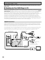
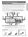
1 Hooking Up Your DVD Player & TV
In order to use Dolby Digital/DTS soundtracks, which are at the heart of home theater, you need to hook up your
DVD player with digital audio connections. You can do this by either a coaxial or an optical connection, you don’t
need to do both. The quality of these two types of connections is the same but since some DVD players only
have one type of digital terminal you need to figure out which yours has and hook it up to the appropriate
terminal on the receiver. In order to do this you will need the proper cable. For coaxial connections you can use a
regular RCA video cord or the specially-made coaxial cords, they have the same type of plugs. For optical
connections you will need a special optical cable which you can buy at your local stereo store. For more
information on cords and cables see page 23. You should also hook up your DVD player with analog audio
connections. Use regular RCA stereo cords for these connections. Also hook up the video connection on your
DVD player, and your TV to this receiver. For your TV it's easiest to use a regular composite (RCA) video cord, as
shown below. It is important that you hook up your TV (or monitor) in order to see a video image as well as the
on screen displays (OSDs) shown by this receiver (for more on this see page16).
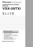
Digital Connections
Some DVD players have both coaxial and optical terminals, but there is no need to connect both. If your DVD
player has a coaxial terminal (not a PCM-only output) for the audio out hook it up using this terminal. Follow the
diagram below. This is the best scenario, as you will be able to follow the default settings of this receiver and
won't need to assign the digital inputs (you should use DIGITAL IN 3).
If your DVD player only has an optical terminal for the audio output you can hook it up using one of the DIGITAL
IN terminals between 1-2 (for example, DIGITAL IN 2). In this case, you will need to assign the digital input
(which means tell the receiver which input you used for your DVD digital audio). See page 12 for this.
RCA stereo cord
RCA video cord
R
MONITOR
OUT
ANALOG
AUDIO
L
R
R
L
L
VIDEO
IN 1
VIDEO
OUT
(TV/
SAT)
DVD/
LD
IN
IN 2
R
VIDEO
L
S VIDEO
DVD player
(CD-R/
TAPE1)
ASSIGNABLE
PCM/
2DIGITAL /
DTS/MPEG
IN 3
(DVD/
LD)
IN 4
(CD)
OUT1
FM UNBAL 75Ω
AM LOOP
ANTENNA
MULTI-ROOM
& SOURCE
MONITOR OUT
MULTI-ROOM
& SOURCE
IN
Y
CENTER
R OUT L
PB
MONITOR
OUT
OUT2
IN 1
(TV/
SAT)
FRONT
R
PR
L
IN
SURROUND
IN
CD-R/
(CD-R/ TAPE1
TAPE1) OUT
IN 4
(CD)
OUT
L
R
SURROUND
Y
TV/
SAT
IN
PHONO/
LINE
IN
DVD/
LD
IN
R
L
AUDIO
R
L
AUDIO
SUB
WOOFER
CENTER
SURROUND
BACK
L
S VIDEO
VIDEO
ª
·
·
PB
PR
R
VIDEO
SURROUND
CENTER
R BACK R L
ª
L
R
IN
FRONT L L
R SURROUND
REMOTE IN
PR
IN
VCR2
OUT
CD
DIGITAL
MULTI-ROOM
& SOURCE
FRONT
PLAY
IN
REC
USB
AUDIO
PB
L
R
MD/
TAPE2
(not a PCM-only
output)
Y (DVD/LD) IN 1
(Single)
SURROUND
BACK
OUT
REC
IN 3
(DVD/
LD)
L
R
VCR1/
DVR
MULTI CH IN
RS-232C
You only need to make
one DIGITAL connection.
(TV/SAT) IN 2
COMPONENT VIDEO
coaxial cord
optical cord
10
OUTPUT
12V
TRIGGER
(DC OUT12V/
100mA MAX)
L
R
PLAY
IN 2
AC OUTLET
RCA video cord
SUB
WOOFER
CONTROL
OUT
DIGITAL
ASSIGNABLE
MONITOR OUT
PRE OUT
VIDEO INPUT
Easy Setup Guide Part1
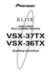
Home theater is designed to be setup with five, or seven speakers (front left & right; center; surround left &
right; and, optimally, surround back left & right) and a subwoofer, but you can use this receiver with fewer
speakers. Hook up the speakers you have to the A speaker terminals on the back of the receiver. If you only
have two speakers hook them up as FRONT. If you have three hook up the single speaker as CENTER. Follow
the diagram below in order to hook up all your speakers. A center speaker is very important for watching films
because in digital soundtracks the dialog comes from the center speaker. If you do not have a center speaker
you must tell the receiver the center channel is off or when you listen to digital soundtracks you won't hear any
dialog. This can be done automatically by following the AUTO SURROUND SOUND SETUP instructions from
page 13 in this Easy Setup Guide.
If possible, use surround back speakers. These speakers are important to take full advantage of all the sound
channels on new, eight channel home theater DVDs. The diagram below also explains how to hook up a
subwoofer which provides realistic bass sounds. For the subwoofer use a mono (single plug) RCA cord and for
the other speakers use regular speaker cords. See pages 109–110 for advice on speaker placement.
Make sure you connect the speaker on the right to the R terminal and the speaker on the left to the L terminal.
Also make sure the positive and negative (+/–) terminals on the receiver match those on the speakers.
Powered
subwoofer
Front
speaker
(Left)
EASY SETUP GUIDE
2 Speaker Connections
Front
speaker
(Right)
TV/monitor
Center
speaker
INPUT
Surround
speaker
(Left)
ASSIGNABLE
PCM/
2DIGITAL /
DTS/MPEG
ASSIGNABLE
MONITOR OUT
PRE OUT
FM UNBAL 75Ω
AM LOOP
ANTENNA
MULTI-ROOM
& SOURCE
MONITOR OUT
MULTI-ROOM
& SOURCE
IN
OUT1
Y
CENTER
CONTROL
R OUT L
OUT
PB
MONITOR
OUT
OUT2
FRONT
R
IN 1
PR
L
IN
IN 2
SURROUND
IN
CD-R/
MULTI-ROOM
& SOURCE
FRONT
VCR2
OUT
OUT
L
R
SURROUND
Y
SUB
WOOFER
TV/
SAT
IN
PHONO/
LINE
IN
L
AUDIO
R
L
AUDIO
CENTER
SURROUND
BACK
DVD/
LD
IN
R
DIGITAL
S VIDEO
VIDEO
Å
R FRONT L
CENTER
SURROUND BACK /
R
L
ı
ª
MULTI CH IN
RS-232C
·
·
(TV/SAT) IN 2
COMPONENT VIDEO
Surround back
speaker (Left)
memo
R SURROUND L
ª
PB
PR
L
R
VIDEO
SPEAKERS
L
R
REC
IN
REMOTE IN
PR
IN
MD/
TAPE2
CD
USB
AUDIO
PB
L
R
PLAY
IN
IN 4
(CD)
Y (DVD/LD) IN 1
(Single)
SURROUND
BACK
OUT
REC
IN 3
(DVD/
LD)
L
R
VCR1/
DVR
(CD-R/ TAPE1
TAPE1) OUT
Surround
speaker
(Right)
12V
TRIGGER
(DC OUT12V/
100mA MAX)
L
R
PLAY
(TV/
SAT)
AC OUTLET
SUB
WOOFER
Surround back
speaker (Right)
• We recommend speakers with a nominal impedance rated 8 Ω-16 Ω, but you can change the
speaker impedance setting of the receiver (see page 26).
• If you only have one surround back speaker hook it up to the left surround back terminal.
• If you use a THX certified subwoofer use the THX INPUT jack on the subwoofer (if your subwoofer
has one) or switch the filter position to THX on your subwoofer.
• When you attached your speaker wire to the speaker terminal make sure that not even one strand
of wire touches the back of the receiver. If this happens it could short out the receiver.
7 Speaker terminals
1 Twist exposed wire
strands together
tightly.
2 Loosen speaker terminal
and insert exposed wire.
3 Tighten
terminal.
The speaker terminals also
accept single banana plugs.
(Refer to speaker manual for
details.)
3/8 in(10mm)
11
Easy Setup Guide Part1
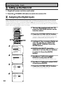
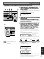
3 Setting up the Main Unit
1 Plug the AC power cord into a wall outlet.
STANDBY/ON button to switch the receiver ON.
2 Press the
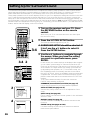
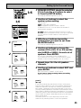
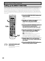
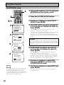
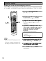
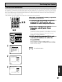
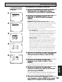
4 Assigning the Digital Inputs
This is only necessary if you did not hook up your DVD player to DIGITAL IN 3 using a coaxial cable but
rather connected it to one of the optical digital inputs. The following example shows how to assign the
DIGITAL IN 2 jack to DVD. Use the arrow buttons (5∞) and the ENTER button on the remote control to
navigate the on-screen display (OSD) on your TV. Conversely, you can use the MULTI JOG dial and ENTER
button, and look at the display, on the Front Panel.
1 Turn on the receiver and your TV,
press the RECEIVER button on the
remote control.
SETUP
SYSTEM RECEIVER
S0URCE
TV
DVD/LD
TV/SAT
OFF
VCR1/
DVR
TV CONT
MULTI CONTROL
2,7
VCR2
VIDEO
CD
MULTI
OPERATION
CD-R/
TAPE1
MD/
TAPE2
TUNER
RECEIVER
DIMMER
LOUDNESS
TONE
EFFECT/CH SEL
1
2
3
SIGNAL SEL
DNR
BASS/TREBLE
5
6
VIDEO SEL
HI-BIT
9
0
7
8
+10 –
DISC
ENTER
MENU
TOP MENU
TUNER EDIT
TRACK
ENTER
EXIT
RETURN
MPX
DTV ON/OFF
DISP MODE
¶
8
SUB TITLE
TUNING
–
1
BAND
STAT ON
DTV MENU C ASS
+
¡
STAT ON +
TUNING
3
System Setup
[
[
[
[
[
[
[
[
4
+
DIRECT ACCESS SEARCH MODE
GUIDE
SYSTEM SETUP
AUDIO
3
4
1. Surround Setup
]
2. THX CINEMA Setup ]
3. Input Assign
]
4. Function Rename ]
5. PHONO/LINE Setup ]
6. Multi Room
]
7. 12V Trigger
]
Exit
]
3.Input Assign
[ Digital-In Select
]
[ Component-In Select ]
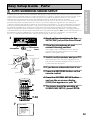
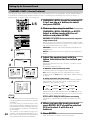
3 Looking at the on-screen display on
your TV, use the 5∞ buttons to
select INPUT ASSIGN. Press the
ENTER button.
4 DIGITAL IN-SELECT should be
selected, if not use the 5∞ buttons
to select it. Press the ENTER
button.
5 Use the 5∞ buttons to select
DIGITAL-2 and press ENTER.
Digital-In Select
[ TV/SAT ]
[ CD-R ]
[ DVD/LD ]
[ CD ]
[Exit]
Digital-In Select
Digital-1
Digital-2
Digital-3
Digital-4
[Exit]
12
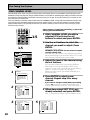
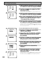
The SYSTEM SETUP menu appears on your TV (if
it doesn't, refer to page 10 to make sure you have
properly connected the receiver to your TV).
6 Use the 5∞ buttons to select DVD/
LD and press ENTER.
Digital-1
Digital-2
Digital-3
Digital-4
6
3-6
2 Press the SYSTEM SETUP button.
The default setting for the DIGITAL-2 jack is CD-R.
[Exit]
5
1
[ TV/SAT ]
[ DVD/LD ]
[ OFF ]
[ CD ]
7 Press the SYSTEM SETUP button.
The receiver exits the setup process.
Easy Setup Guide Part2
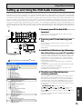
If setting up your surround sound speakers seems like it's going to be an involved task you only need to
use this quick, automatic method, known as the MCACC system, to achieve good surround sound. You'll
need to hook up the microphone so that the receiver can hear and judge the distance, size, sound
character and sound pressure level of the speakers and thus know what settings to make.
First turn the volume down, then plug the microphone into the SETUP MIC jack on the front panel of the
receiver and put the microphone into its stand. If you have a tripod you can affix the mic stand to it.
Follow the step-by-step guide to setting up your surround sound below. This will customize the surround
sound for your listening environment. If you want to personalize your surround sound setups by making
the settings manually go to "Setting up for Surround Sound" (starting on page 36) and "Expert setup"
(starting on page 96). Make sure all the components you need, especially speakers, have been properly
connected before you do the steps described here. Use the arrow buttons (5∞) and the ENTER button on
the remote control to navigate the on-screen display (OSD) on your TV. Conversely, you can use the
MULTI JOG dial and ENTER button, and look at the display, on the Front Panel.
1
MULTI JOG CONTROL
SET UP
RETURN
SIGNAL
SELECT
PHONES
TONE
SPEAKERS
HI-BIT
HI-SAMPLING
SB CH
MODE
STATION TUNING
BAND
CLASS
TONE CONTROL
BASS/TREBLE
TUNER
EDIT
SELECT
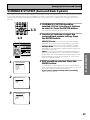
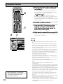
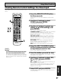
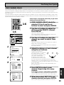
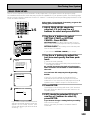
1 Hook up the microphone to the
SETUP MIC jack on the Front Panel.
MULTI ROOM & SOURCE
CONTROL
ON/OFF
L
R
MULTI JOG/ENTER
SETUP
MIC
DIGITAL IN
S-VIDEO
VIDEO
VIDEO INPUT
AUDIO
microphone
stand
microphone
EASY SETUP GUIDE
1 AUTO SURROUND SOUND SETUP
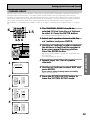
2 Place the microphone at your
normal listening position.
Use a table, chair or something else to put the
microphone at the same height as you usually
listen to your system from.
Front Speaker (R)
Center Speaker
Surround Speaker (R)
Subwoofer
3 Switch on the receiver and your TV.
Make sure your TV is set to this receiver as you
will use the on-screen displays (OSDs) on your TV
to follow these instructions.
Front Speaker (L)
4 If you have a subwoofer turn it on.
Listening Position
Surround Back
Speaker (R)
Surround Speaker (L)
Surround Back Speaker (L)
6 Press the SYSTEM SETUP button
and use the on-screen display
(OSD) that appears on your TV.
SETUP
S0URCE
TV
DVD/LD
TV/SAT
3
SYSTEM RECEIVER
OFF
VCR1/
DVR
TV CONT
MULTI CONTROL
VCR2
6
VIDEO
CD
MULTI
OPERATION
CD-R/
TAPE1
MD/
TAPE2
TUNER
RECEIVER
DIMMER
LOUDNESS
TONE
EFFECT/CH SEL
1
2
3
SIGNAL SEL
DNR
BASS/TREBLE
5
6
VIDEO SEL
HI-BIT
9
0
SYSTEM SETUP
5
4
+
7
8
+10 –
DISC
ENTER
TOP MENU
TUNER EDIT
7-13
TRACK
ENTER
EXIT
AUDIO
7
7 The arrow should be pointing at
SURROUND SETUP, press ENTER.
DIRECT ACCESS SEARCH MODE
GUIDE
MENU
RETURN
MPX
DTV ON/OFF
DISP MODE
¶
8
SUB TITLE
TUN NG
5 Press the RECEIVER button on the
remote control.
BAND
TUN NG
+
System Setup
[1. Surround Setup
[2. THX CINEMA Setup
[3. Input Assign
[4. Function Rename
[5. PHONO/LINE Setup
[6. Multi Room
[7. 12V Trigger
[Exit
]
]
]
]
]
]
]
]
13
Easy Setup Guide Part2
8
[
[
[
[
[
[
10
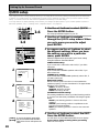
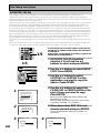
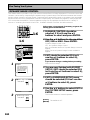
8 Select AUTO SETTING with the 5∞
buttons and press ENTER.
1.Surround Setup
SurrBack System
Auto Setting
Quick
Normal
Expert
Exit
]
]
]
]
]
]
9 Some auto setup instructions will be
listed, make sure to follow them.
Make sure you have: hooked up the microphone and moved
obstacles to the speakers out of the way. If you have a
subwoofer make sure it is turned on and has the volume
turned up.
Auto Surround Setup
Set microphone
Turn on subwoofer
WARNING: The test tones are very loud!! Make sure there
are no infants or small children in the room and that no one
who will be scared, upset or injured by loud noise is present.
You yourself may want to wear earplugs. It is possible to
lower the volume of test tones, but this could result in
incorrect speaker settings.
[ Start ]
[ Cancel ]
\
Auto Surround Setup
10 If you have followed all setup instructions
and warnings above make sure that the
arrow is pointed to START and press
ENTER. Be prepared for loud test tones.
Please Wait
Caution!!
Test tone is
output loudly.
[Cancel]
\
Try to be as quiet as possible after hitting ENTER. The test
tones may take up to 30 seconds.
The volume automatically increases to 0 dB, then the system
will output some test tones and establish ambient noise
levels, the microphone status, and what speakers you hooked
up.
Auto Surround Setup
Now Analyzing •••
Environment Check
Ambient Noise
Microphone
Speaker YES/NO
[OK]
[OK]
[OK]
[Cancel]
\
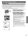
11
Check!!
Front
[ YES
Center
[ YES
Surround
[ YES
SurrBack
[ YES
Subwoofer [ YES
]
]
]
2]
]
[OK]
[Retry]
[ERR Fix SP.]
[Return to Menu]
Auto Surround Setup
Now Analyzing •••
Surround Analysis
Speaker Systems
Channel Delay
Channel Level
Acoustic Cal EQ
[OK]
[OK]
[OK]
[OK]
[Cancel]
Speaker Systems Check
Front
Center
Surround
SurrBack
Subwoofer
[Next ]
[Exit ]
14
[SMALL]
[SMALL]
[SMALL]
[SMALL X2]
[ YES ]
11 Check the speaker settings on the OSD
If they match your speaker configuration make sure OK is
selected and press ENTER. The test tones will be output
loudly again. The test tones may take up to 5 minutes this
time.
After it has finished, you see the SPEAKER SYSTEMS CHECK
screen. If you want to view the settings select NEXT and
press ENTER repeatedly. If not, simply go to step 13.
If they do not match the speaker configuration you hooked up
and you want to try again select RETRY with 5∞ buttons and
press ENTER. Follow the instructions above from step 10.
If you get an error message instructing you to do something,
follow the instructions and RETRY with 5∞ buttons and
press ENTER.
If the speaker settings do not match the speaker configuration you connected and you want to input the settings
manually select ERR=FIX SP with the 5∞ buttons, press
ENTER. Go to step 12.
If you see an ERR message in the right side column, there
may be a problem with the speaker connection. If selecting
RETRY doesn't fix the problem, turn off the power and check
the speaker connections.
Easy Setup Guide Part2
memo
The system will output another series of test tones to
establish the proper channel level, channel delay and
acoustic calibration EQ. Again, be prepared for loud
test tones.
EASY SETUP GUIDE
• Make sure the room environment follows the
guidelines displayed on the OSD during auto
setup. If the room environment is not optimal
for auto setup (too much ambient noise,
obstacles blocking the speakers from the
microphone, etc.) the final settings may be
incorrect. Check for household appliances (air
conditioner, fridge, fan, etc.) that may be
affecting the environment and switch them off
if necessary.
• Screens will turn off after three minutes and
the receiver will automatically exit from the
setup process.
• If you leave CHECK!! or other error message
on the screen for three minutes, or you
choose CANCEL at anytime during the setup,
the settings made up to that point will be
cleared.
• After completing the AUTO SURROUND
SOUND SETUP, ACOUSTIC CAL EQ ON (ALL
CH ADJUST) is set automatically.
• Some older TVs may interfere with the
operation of the mic. If this is the case turn
the TV off when doing AUTO SURROUND
SOUND SETUP.
12 Use the ∞5 buttons to select a
speaker press ENTER. Then use the
∞5 buttons to select the size of
each speaker individually. Press
ENTER. Use the ∞5 buttons to
select OK and press ENTER.
After it has finished, you see the SPEAKER
SYSTEMS CHECK screen. If you want to view the
settings select NEXT and press ENTER repeatedly.
If not, simply go to the next step.
13 Select RETURN and press ENTER to
go back to the SYSTEM SETUP
menu. Then choose EXIT to
complete the auto surround sound
setup and return to normal use.
You should now have settings that will give you
good surround sound. The MCACC indicator will
light and the surround sound settings are
complete.
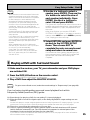
2 Playing a DVD with Surround Sound
1 Make sure the receiver, your TV, your subwoofer and your DVD player
are switched ON.
2 Press the DVD/LD button on the remote control.
You should see DVD/LD in the display on the receiver.
3 Play a DVD then adjust the MASTER VOLUME.
memo
To get a more refined sound, make the sound settings in "Expert setup" (see page 96).
If you're having trouble getting surround sound playback look at this
Frequently Asked Questions (FAQ) guide:
Q1: Even though I'm playing a DVD I'm not getting 5.1 channel playback.
A1: Either the DVD is not set for digital output, or the Dolby Digital/DTS output settings are not
correct.
Set the DVD player to output a digital signal and set the Dolby Digital and DTS output properly. If you are
unsure how to do this check the DVD initial setup in the manual that came with your DVD player.
Q2: There is no sound from the subwoofer or it is very low.
A2: There is a good possibility you haven't reached a part of the DVD that has an LFE channel
(which feeds the subwoofer) yet. The LFE channel only appears in selected parts of the
soundtrack. Continue playing and listen for the subwoofer.
If you want to hear more sound from the subwoofer set it to PLUS (see page 40 for more information
and consult the memo on page 41).
15
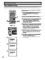
Connecting Your Equipment
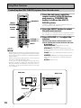
Connecting your TV
Before making or changing the connections, switch off the power and disconnect the power cord from
the AC outlet.
Connect your TV to the jacks as shown below. Hook up with either component video, S video, or composite video cords (the quality descends in this order) but you must use the same type of video cords to
hook up your DVD player (and all other video components) as you use to hook up your TV. If you
plan to hook up your DVD player with component video cords hook up your TV with them as well but in
this case you must also hook up your TV with composite video or S video cords because you won't be
able to see the receiver's on-screen displays with a component video hook up. Composite video cords,
which look just like regular RCA audio cords (see page 20) but have only one cable are the most common.
CAUTION:
Don't confuse the
MONITOR OUT for
your TV with the
MULTI ROOM &
SOURCE MONITOR OUT (for the
MULTI ROOM
feature only).
ASSIGNABLE
PCM/
2DIGITAL /
DTS/MPEG
OUT1
ASSIGNABLE
MONITOR OUT
PRE OUT
FM UNBAL 75Ω
AM LOOP
ANTENNA
MULTI-ROOM
& SOURCE
MONITOR OUT
MULTI-ROOM
& SOURCE
IN
Y
CENTER
SUB
WOOFER
CONTROL
R OUT L
OUT
OUT2
IN 1
(TV/
SAT)
IN 2
R
L
IN
CD-R/
VCR1/
DVR
SURROUND
MULTI-ROOM
& SOURCE
L
R
VCR2
OUT
OUT
SURROUND
Y
Y
L
R
IN
PHONO/
LINE
IN
SUB
WOOFER
L
AUDIO
R
L
AUDIO
CENTER
SURROUND
BACK
DVD/
LD
IN
R
S VIDEO
VIDEO
S Video
PB
MULTI CH IN
S-VIDEO
PB
PR
L
R
VIDEO
VIDEO
L
R
TV/
SAT
IN
VIDEO IN
COMPONENT
REMOTE IN
PR
REC
SV
IDE
O
PB
IN
MD/
TAPE2
DIGITAL
Y (DVD/LD) IN 1
(Single)
FRONT
PLAY
IN
CD
USB
AUDIO
L
R
SURROUND
BACK
OUT
REC
IN 4
(CD)
L
R
PLAY
(CD-R/ TAPE1
TAPE1) OUT
IN 3
(DVD/
LD)
12V
TRIGGER
(DC OUT12V/
PR 100mA MAX)
FRONT
IN
TV/monitor
PB
MONITOR
OUT
PR
RS-232C
(TV/SAT) IN 2
COMPONENT VIDEO
Component video
S video cables produce
clearer picture
reproduction by sending
separate signals for the
luminance and the color.
Y
Green
Blue
Red
PB
PR
The video signal is
divided into the
luminance (Y) signal and
the color (PB and PR)
signals. In this way,
interference between
the signals is avoided.
Composite Video
Composite video cords are the most common or standard video cord but also
the lowest quality. The color on the connector is yellow to distinguish it from
regular RCA audio cords which have white and red connectors (see page 20).
It is important to use a true composite video cord and not an audio cord
(though they look exactly the same) because the impedance is different and
this will affect the picture quality.
Component Video Input Default Settings
If you use component video cords to hook up your video equipment it is easiest to do so following the
default settings, which are listed below. Remember you must use component video cords from your
video source (for example, a DVD player) to the receiver and from the receiver to your TV (or monitor). If
you don't follow the default settings below you must assign the inputs you used with the "Assigning the
Component Video Inputs" procedure. See page 92 to do this.
The default settings are:
16
COMPONENT VIDEO IN 1: DVD/LD
COMPONENT VIDEO IN 2: TV/SAT
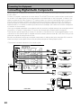
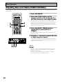
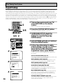
Connecting Your Equipment
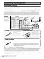
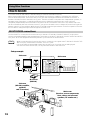
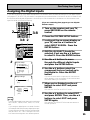
Connecting Video Components
Before making or changing the connections, switch off the power and disconnect the power cord from
the AC outlet.
Hook up your video signal with either component video, S video or composite video cords (the
quality descends in this order) but you must use the same type of cord as you used to hook up
your TV.
For the audio signal, in order to use digital soundtracks like Dolby Digital or DTS you must hook up a digital
input, with either a coaxial or optical cord (see pages 22 & 23). It is also a good idea to hook up your
components with analog audio connections as well.
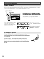
Connecting a DVD player
Before making or changing the connections, switch off the power and disconnect the power cord from
the AC outlet.
Hook up your audio signal with either a coaxial or optical digital cords (you don't need to do both). If you
hook up your DVD/LD player using component video cable connections you might need to setup your
DVD player for component video output as well. See your DVD manual for details. If you have a DVDAudio or Super Audio CD (SACD) compatible player, see "Connecting to the Multi Channel Analog Inputs"
on page 21.
PREPARATION
If you want to record from your DVD player composite (or S video) cord connections and analog audio
connections are necessary.
PREPARATION
Connect your video components as shown on this and the following page. For video components (for
example, a DVD player) there are two types of connections to make, video and audio.
You need to hook up your audio with analog connections as well.
*The arrows indicate the direction of the signal.
ASSIGNABLE
PCM/
2DIGITAL /
DTS/MPEG
OUT1
AM LOOP
ANTENNA
MULTI-ROOM
& SOURCE
MONITOR OUT
MULTI-ROOM
& SOURCE
IN
CONTROL
R OUT L
OUT
IN 1
IN 2
CENTER
FRONT
R
PR
L
IN
CD-R/
VCR1/
DVR
SURROUND
IN 4
(CD)
OUT
VIDEO
PB
MULTI-ROOM
& SOURCE
L
FRONT
PLAY
IN
MD/
TAPE2
VCR2
OUT
OUT
PHONO/
LINE
IN
DVD/
LD
IN
L
AUDIO
R
L
AUDIO
Y
SURROUND
BACK
L
R
MULTI CH IN
PR
PB
PR
S VIDEO
VIDEO
PB
L
CENTER
SUB
WOOFER
VIDEO
DVD player
Y
S-VIDEO
R
TV/
SAT
IN
VIDEO
OUT
COMPONENT
L
R
SURROUND
REC
IN
REMOTE IN
PR
IN
R
DIGITAL
Y (DVD/LD) IN 1
(Single)
R
CD
USB
AUDIO
L
R
SURROUND
BACK
REC
(not a PCM-only output)
3
2
12V
TRIGGER
(DC OUT12V/
100mA MAX)
L
R
IN
DIGITAL OUT
1
SUB
WOOFER
PB
PLAY
(CD-R/ TAPE1
TAPE1) OUT
IN 3
(DVD/
LD)
Y
MONITOR
OUT
OUT2
(TV/
SAT)
ASSIGNABLE
MONITOR OUT
PRE OUT
FM UNBAL 75Ω
RS-232C
(TV/SAT) IN 2
COMPONENT VIDEO
ANALOG
AUDIO
L
R
memo
• Be sure to make either a digital coaxial or digital optical connection (pictured as DIGITAL
jack 3 or DIGITAL jack 2 in this diagram) but you don't need to make both.
• If your digital connections are different than the default settings you will need to assign
the digital jacks to the proper component(s) with the "Assigning the Digital Inputs"
procedure. See page 91 to do this.
• If your component video connections are different from the default settings, you will
need to assign them with "Assigning the Component Video Inputs". See page 92 to do
this.
17
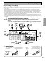
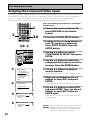
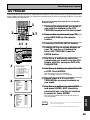
Connecting Your Equipment
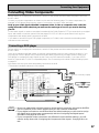
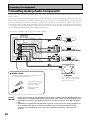
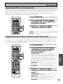
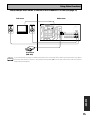
Connecting VCRs or DVRs
Before making or changing the connections, switch off the power and disconnect the power cord from
the AC outlet.
Connect the video out of your VCR/DVR using either S video or composite video cords, depending on how
you connected the receiver to your TV (see page 16). Use analog audio cords for the audio signal. To
record, you also need to connect a set of audio/video outputs from the receiver to the audio/video inputs
on your VCR/DVR. Note that to record video from a source component, the video connection from the
source to the receiver and from the receiver to the recorder must be the same type.
ASSIGNABLE
PCM/
2DIGITAL /
DTS/MPEG
OUT1
ANTENNA
MULTI-ROOM
& SOURCE
IN
MULTI-ROOM
& SOURCE
MONITOR OUT
Y
CENTER
SUB
WOOFER
CONTROL
R OUT L
OUT
IN 1
(TV/
SAT)
IN 2
FRONT
R
L
IN
SURROUND
IN
CD-R/
VCR1/
DVR
VCR2
OUT
OUT
USB
AUDIO
IN
TV/
SAT
IN
PHONO/
LINE
IN
DVD/
LD
IN
R
DIGITAL
L
R
SURROUND
Y
R
L
AUDIO
L
AUDIO
SUB
WOOFER
CENTER
SURROUND
BACK
PR
OUT
IN
AUDIO
(PLAY)
AUDIO
(REC)
MULTI CH IN
L
L
R
R
RS-232C
(TV/SAT) IN 2
S VIDEO
VIDEO
VCR 1/DVR
PB
L
R
VIDEO
S-VIDEO
L
R
CD
S-VIDEO
REMOTE IN
PR
REC
VIDEO
MULTI-ROOM
& SOURCE
FRONT
IN
MD/
TAPE2
VIDEO
PB
L
R
PLAY
IN
L
R
(Single)
SURROUND
BACK
OUT
L
R
Y (DVD/LD) IN 1
L
R
REC
IN 4
(CD)
L
R
PLAY
(CD-R/ TAPE1
TAPE1) OUT
IN 3
(DVD/
LD)
PB
12V
TRIGGER
(DC OUT12V/
PR 100mA MAX)
MONITOR
OUT
OUT2
IN
AUDIO
(REC)
ASSIGNABLE
MONITOR OUT
PRE OUT
AM LOOP
FM UNBAL 75Ω
OUT
AUDIO
(PLAY)
VIDEO
VIDEO
S-VIDEO
S-VIDEO
COMPONENT VIDEO
VCR 2
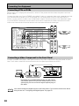
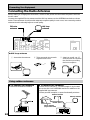
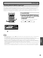
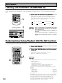
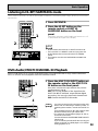
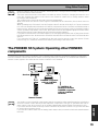
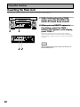
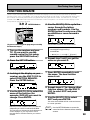
Connecting a Video Component to the Front Panel
Connect a portable DVD player, video game console or any video component to the front panel as show
here. Front video connections are accessed via the front panel input selector as VIDEO.
STATION TUNING
MULTI ROOM & SOURCE
SELECT
DIGITAL IN
COLOR
BRIGHT
MONITOR
VIDEO-IN/OUT
PHONES
ON/OFF
S-VIDEO
VIDEO
VIDEO INPUT
CONTROL
ON/OFF
L
R
AUDIO
AUDIO-IN/OUT
HOLD
DIGITAL OUT (OPTICAL)
Be careful! For portable DVD players you will need a
specialized optical cord (for the audio) that has a mini
optical plug on one end and a regular optical plug on
the other.
memo
18
You cannot assign the digital input on the front panel. If you want to learn more about
this process see "Assigning the Digital Inputs" on page 91.
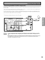
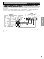
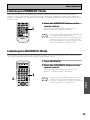
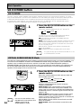
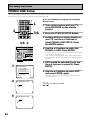
Connecting Your Equipment
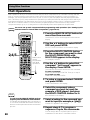
Connecting Satellite TV (SAT) Components
Before making or changing the connections, switch off the power and disconnect the power cord from
the AC outlet.
For the audio signal, in order to use digital soundtracks broadcast you must hook up a digital input. Use
either a coaxial or optical cable, it doesn't matter which (see pages 22–23). We recommend hooking up
your audio with analog cables as well (see below).
*The arrows indicate the direction of the TV signal.
VIDEO
COMPONENT
PREPARATION
Hook up the video signal with either component video, S video, or composite video cords, depending on
how you connected the receiver to your TV (see page 16).
VIDEO
OUT
Y
OUT1
ASSIGNABLE
MONITOR OUT
PRE OUT
FM UNBAL 75Ω
AM LOOP
ANTENNA
MULTI-ROOM
& SOURCE
MONITOR OUT
MULTI-ROOM
& SOURCE
IN
R OUT L
SUB
WOOFER
IN 1
IN 2
FRONT
R
PR
L
IN
SURROUND
IN
CD-R/
IN 4
(CD)
VCR1/
DVR
MD/
TAPE2
VCR2
OUT
OUT
TV/
SAT
IN
SUB
WOOFER
PHONO/
LINE
IN
DVD/
LD
IN
SURROUND
BACK
L
AUDIO
R
L
AUDIO
Y
PB
PR
L
S VIDEO
VIDEO
R
L
CENTER
R
VIDEO
DIGITAL
L
L
R
SURROUND
IN
DIGITAL
REMOTE IN
PR
R
R
memo
MULTI-ROOM
& SOURCE
FRONT
IN
CD
DIGITAL
PB
L
R
PLAY
IN
ANALOG
AUDIO
Y (DVD/LD) IN 1
(Single)
SURROUND
BACK
OUT
REC
USB
AUDIO
L
R
REC
12V
TRIGGER
(DC OUT12V/
100mA MAX)
L
R
PLAY
(CD-R/ TAPE1
TAPE1) OUT
IN 3
(DVD/
LD)
Satellite tuner
PB
MONITOR
OUT
OUT2
(TV/
SAT)
PR
Y
CENTER
CONTROL
OUT
S-VIDEO
PREPARATION
PB
ASSIGNABLE
PCM/
2DIGITAL /
DTS/MPEG
MULTI CH IN
RS-232C
(TV/SAT) IN 2
COMPONENT VIDEO
• If your component video connections are different from the default settings, you will
need to assign them with "Assigning the Component Video Inputs". See page 92 to do
this.
• If your digital connections are different than the default settings you will need to assign
the digital jacks to the proper component(s) with the "Assigning the Digital Inputs"
procedure. See page 91 to do this.
19
Connecting Your Equipment
Connecting Analog Audio Components
Before making or changing the connections, switch off the power and disconnect the power cord from
the AC outlet.
Connect your audio components to the jacks as shown below. These are all analog connections and your
analog audio components (turntable, cassette deck) use these jacks. Remember that for components you
want to record with you need to hook up four plugs (a set of stereo ins and a set of stereo outs), but for
components that only play (like a turntable) you only need to hook up one set of stereo plugs (two plugs).
If you want to record to/from digital components (like a CD-R) to/from analog components you must hook
up your digital equipment with these analog connections.
*The arrows indicate the direction of the audio signal.
ANALOG
OUTPUT
ASSIGNABLE
PCM/
2DIGITAL /
DTS/MPEG
OUT1
PRE OUT
AM LOOP
FM UNBAL 75Ω
ANTENNA
MULTI-ROOM
& SOURCE
IN
MULTI-ROOM
& SOURCE
MONITOR OUT
CENTER
L
SUB
WOOFER
R
CONTROL
R OUT L
OUT
MONITOR
OUT
OUT2
IN 1
(TV/
SAT)
IN 2
L
PLAY
IN
IN
CD-R/
VCR1/
DVR
SURROUND
OUT
L
L
R
R
L
R
IN
MD/
TAPE2
VCR2
OUT
OUT
IN
PHONO/
LINE
IN
R
R
L
AUDIO
L
AUDIO
Recorder 1 (CD-R/TAPE)
L
R
SURROUND
L
R
CD
DIGITAL
INPUT
(REC)
OUTPUT
(PLAY)
(Single)
FRONT
PLAY
IN
REC
USB
AUDIO
ANALOG
L
R
SURROUND
BACK
REC
IN 4
(CD)
L
R
(CD-R/ TAPE1
TAPE1) OUT
IN 3
(DVD/
LD)
CD player
FRONT
R
TV/
SAT
IN
SUB
WOOFER
DVD/
LD
IN
SURROUND
BACK
CENTER
S VIDEO
VIDEO
INPUT
(REC)
L
L
R
R
L
R
VIDEO
ANALOG
OUTPUT
(PLAY)
MULTI CH IN
Recorder 2 (MD/TAPE)
7 Audio cords
Use (RCA) audio cords (not supplied) to connect the audio components.
memo
20
L
Connect red plugs to
R (right) and white
plugs to L (left).
R
Be sure to insert
completely.
Turntable
If your turntable has a ground
wire, connect it to the signal
ground terminal (H).
• If you want to hook up any equipment other than a turntable to the PHONO/LINE jack
please go to the PHONO/LINE Setup (see page 94) and choose the LINE setting. If your
turntable has a phono pre-amplifier (most do not) please choose the LINE setting as
well.
• Depending on where the cassette deck is placed, noise may occur during playback of
your cassette deck which is caused by leakage flux from the transformer in the
receiver. If you experience noise, move the cassette deck farther away from the
receiver.
Connecting Your Equipment
Connecting to the Multi Channel Analog Inputs (DVD-Audio or Super
Audio CD (SACD) compatible player)
Before making or changing the connections, switch off the power and disconnect the power cord from
the AC outlet.
ASSIGNABLE
PCM/
2DIGITAL /
DTS/MPEG
OUT1
ASSIGNABLE
MONITOR OUT
PRE OUT
FM UNBAL 75Ω
AM LOOP
ANTENNA
MULTI-ROOM
& SOURCE
MONITOR OUT
MULTI-ROOM
& SOURCE
IN
Y
CENTER
SUB
WOOFER
CONTROL
R OUT L
OUT
IN 1
(TV/
SAT)
IN 2
FRONT
PR
L
IN
IN
CD-R/
VCR1/
DVR
(CD-R/ TAPE1
TAPE1) OUT
SURROUND
IN 4
(CD)
VCR2
OUT
OUT
IN
PHONO/
LINE
IN
DVD/
LD
IN
R
memo
L
AUDIO
R
L
AUDIO
SURROUND BACK
L
L
R
R
R
L
SURROUND
Y
L
SUB
WOOFER
CENTER
SURROUND
BACK
PB
PR
L
R
S VIDEO
VIDEO
SUB
WOOFER
L
REMOTE IN
PR
VIDEO
CENTER
MULTI-ROOM
& SOURCE
L
R
R
TV/
SAT
IN
SURROUND
PB
R
MD/
TAPE2
FRONT
(Single)
IN
REC
DIGITAL
Y (DVD/LD) IN 1
FRONT
PLAY
IN
CD
USB
AUDIO
L
R
SURROUND
BACK
OUT
REC
IN 3
(DVD/
LD)
L
R
PLAY
12V
TRIGGER
(DC OUT12V/
100mA MAX)
MULTI CH IN
PREPARATION
OUT2
R
ANALOG
PB
MONITOR
OUT
Components equipped with
5.1 (7.1) channel analog output jack
PREPARATION
If you have a DVD-Audio or Super Audio CD (SACD) compatible player, or are using an external Dolby
Digital/DTS decoder, connect it to the multichannel analog inputs as shown below.
RS-232C
(TV/SAT) IN 2
COMPONENT VIDEO
If you use only one surround back input, be sure to hook up to the SURROUND BACK Ò
jack.
21
Connecting Your Equipment
Connecting Digital Audio Components
Before making or changing the connections, switch off the power and disconnect the power cord from
the AC outlet.
Connect your digital components as shown below. The VSX-45TX has two coaxial and two optical inputs
for a total of four digital inputs on the rear panel plus one digital input on the front panel. In order to use
digital soundtracks like Dolby Digital or DTS (among others) you need to make digital audio connections.
You can do this by either a coaxial or an optical connection (you don’t need to do both). The quality of
these two types of connections is the same but since some digital components only have one type of
digital terminal, it is a matter of matching like with like (for example, the coaxial out from the component
to coaxial in on the receiver).
Hook up your digital equipment in accordance with this receiver's default settings (see next page) unless
you want to, or need to, change them. To do this see "Assigning the Digital Inputs" on page 91.
There are two optical digital out jacks (the CD recorder is connected to one in the diagram below). If you
connect this to the optical input on a digital recorder (currently these include MD, DAT and CD-R) you can
make direct digital recordings with this unit.
We also recommend hooking up your digital components to analog audio jacks (see page 20) in order to
make recordings (some digital sources may be protected against making digital copies).
*The arrows indicate the direction of the audio signal.
ASSIGNABLE
PCM/
2DIGITAL /
DTS/MPEG
OUT1
PRE OUT
AM LOOP
FM UNBAL 75Ω
ANTENNA
MULTI-ROOM
& SOURCE
MONITOR OUT
MULTI-ROOM
& SOURCE
IN
CENTER
SUB
WOOFER
DIGITAL
OUTPUT
CONTROL
R OUT L
OUT
MONITOR
OUT
OUT2
IN 1
(TV/
SAT)
IN 2
FRONT
R
L
IN
SURROUND
IN
CD-R/
FRONT
PLAY
IN
IN
MD/
TAPE2
VCR2
OUT
OUT
IN
PHONO/
LINE
IN
R
DIGITAL
L
AUDIO
R
SURROUND
TV/
SAT
IN
SUB
WOOFER
DVD/
LD
IN
SURROUND
BACK
L
AUDIO
CD recorder
L
R
L
S VIDEO
VIDEO
OUTPUT
CENTER
R
VIDEO
DIGITAL
L
R
CD
USB
AUDIO
Satellite tuner
INPUT
(REC)
L
R
REC
B type
DIGITAL
OUTPUT
(PLAY)
(Single)
SURROUND
BACK
OUT
REC
IN 4
(CD)
DIGITAL
L
R
VCR1/
DVR
(CD-R/ TAPE1
TAPE1) OUT
IN 3
(DVD/
LD)
L
R
PLAY
MULTI CH IN
(not a PCM-only output) DVD player
DIGITAL
OUTPUT
CD player
A type
USB cable
22
PC
Connecting Your Equipment
7 Coaxial cords/Optical cables
Coaxial cord
(or standard [composite]
Optical cable
video cord)
Be sure to insert completely and in the case of
the optical cable, right-side up. If it is inserted
improperly it can break the shutter on the
optical terminal (this won't, however, affect the
connection or insertion of an optical cable).
Unlike analog connections, the jacks for digital connections are not dedicated to one type of component,
they can be used freely. Thus you must tell the receiver what digital component is connected to which
jack so your components will be in sync with the names on the remote control buttons and the like. To
avoid having to assign the digital inputs you can hook up your equipment in accordance with the receiver's
default settings.
PREPARATION
Digital Input Default Settings
PREPARATION
Commercially available digital audio coaxial
cords (standard video cords can also be used) or
optical cables (not supplied) are used to connect
digital components to this receiver.
The default settings are:
DIGITAL IN 1 (optical): TV/SAT
DIGITAL IN 2 (optical): CD-R/TAPE1
DIGITAL IN 3 (coaxial): DVD/LD
DIGITAL IN 4 (coaxial): CD
See "Assigning the Digital Inputs" on page 91 if the way you hook up your equipment is different from the
default settings listed here.
23
Connecting Your Equipment
Connecting the Radio Antennas
Before making or changing the connections, switch off the power and disconnect the power cord from
the AC outlet.
Connect the supplied FM wire antenna and the AM loop antenna to the ANTENNA terminals as shown
below. These antennas should provide adequate reception quality in most cases, but connecting outdoor
antennas should noticeably improve sound quality.
FM wire
antenna
AM loop
antenna
ASSIGNABLE
PCM/
2DIGITAL /
DTS/MPEG
OUT1
ASSIGNABLE
MONITOR OUT
PRE OUT
FM UNBAL 75Ω
AM LOOP
ANTENNA
MULTI-ROOM
& SOURCE
MONITOR OUT
MULTI-ROOM
& SOURCE
IN
Y
CENTER
CONTROL
R OUT L
OUT
IN 1
(TV/
SAT)
IN 2
PB
MONITOR
OUT
OUT2
FRONT
R
PR
L
R
PLAY
IN
IN
CD-R/
VCR1/
DVR
(CD-R/ TAPE1
TAPE1) OUT
OUT
AC OUTLET
SUB
WOOFER
L
SURROUND
R
SURROUND
BACK
12V
TRIGGER
(DC OUT12V/
100mA MAX)
L
Y (DVD/LD) IN 1
(Single)
P
7 AM loop antenna
1 Assemble the antenna.
2 Twist exposed wire strands
together and insert.
10
in. (
3/8
3 Attach to a wall, etc. (if
desired) and face toward
the direction providing
the best reception.
)
mm
Using outdoor antennas
7 To improve FM reception
7 To improve AM reception
Connect an external FM antenna.
Connect a 15 to 18 feet (5 – 6 meter) length of vinyl-coated
wire to the AM LOOP ANTENNA terminal in addition to the
supplied AM loop antenna.
For best possible reception, suspend horizontally outdoors.
Outdoor antenna
AM loop antenna
15–18 ft. (5–6 m)
Indoor antenna
(vinyl-coated wire)
24
Connecting Your Equipment
Connecting Speakers
Before making or changing the connections, switch off the power and disconnect the power cord from
the AC outlet.
One of the latest features of home theater is the use of surround back speakers. These speakers add
even greater realism in movie sound effects and some new discs with soundtracks in Dolby Digital or DTS
incorporate these channels. See page 27 for speaker placement.
In general, make sure you connect the speaker on the right to the R terminal and the speaker on the left
to the L terminal. Also make sure the positive and negative (+/–) terminals on the receiver match those on
the speakers.
• We recommend speakers with a nominal impedance rated 8 Ω-16 Ω, but you can change the
speaker impedance setting of the receiver (see page 26).
• If you only have one surround back speaker hook it up to the left surround back
terminal.
• If you use a THX certified subwoofer use the THX INPUT jack on the subwoofer (if your
subwoofer has one) or switch the filter position to THX on your subwoofer.
Powered
subwoofer
Front
speaker
(Left)
Front
speaker
(Right)
TV/monitor
PREPARATION
memo
PREPARATION
We recommend a full complement of seven speakers and a subwoofer as shown here but, naturally,
everyone's home setup will vary. Simply connect the speakers you have in the manner described below.
Center
speaker
INPUT
Surround
speaker
(Left)
ASSIGNABLE
PCM/
2DIGITAL /
DTS/MPEG
AM LOOP
ANTENNA
MULTI-ROOM
& SOURCE
MONITOR OUT
MULTI-ROOM
& SOURCE
IN
OUT1
ASSIGNABLE
MONITOR OUT
PRE OUT
FM UNBAL 75Ω
Y
CENTER
CONTROL
R OUT L
OUT
PB
MONITOR
OUT
OUT2
FRONT
R
IN 1
PR
L
IN 2
IN
IN
CD-R/
VCR1/
DVR
(CD-R/ TAPE1
TAPE1) OUT
SURROUND
IN 3
(DVD/
LD)
MULTI-ROOM
& SOURCE
FRONT
VCR2
OUT
OUT
IN
TV/
SAT
IN
PHONO/
LINE
IN
DVD/
LD
IN
R
L
AUDIO
R
L
AUDIO
REMOTE IN
PR
SURROUND
Y
CENTER
SURROUND
BACK
R FRONT L
CENTER
SURROUND BACK /
R
L
ı
ª
S VIDEO
MULTI CH IN
RS-232C
·
·
(TV/SAT) IN 2
COMPONENT VIDEO
Surround back
speaker (Left)
Surround back
speaker (Right)
7 Speaker terminals
1 Twist exposed wire
strands tightly
together.
R SURROUND L
ª
PB
PR
L
R
VIDEO
Å
L
SUB
WOOFER
VIDEO
SPEAKERS
L
R
R
CD
DIGITAL
PB
L
IN
MD/
TAPE2
REC
USB
AUDIO
Y (DVD/LD) IN 1
(Single)
R
PLAY
IN
IN 4
(CD)
L
R
SURROUND
BACK
OUT
REC
Surround
speaker
(Right)
12V
TRIGGER
(DC OUT12V/
100mA MAX)
L
R
PLAY
(TV/
SAT)
AC OUTLET
SUB
WOOFER
2 Loosen speaker terminal
and insert exposed wire.
3 Tighten
terminal.
The speaker terminals also
accept single banana plugs.
(Refer to speaker manual
for details.)
3/8 in(10mm)
25
Connecting Your Equipment
Speaker impedance
You can change the speaker impedance for VSX-45TX but we recommend using speakers with an impedance of 8 Ω-16 Ω (the default setting). If you are using 6 Ω- less than 8 Ω impedance speakers, you need
to change the impedance setting. Use any speaker rated between 6 Ω-16 Ω.
STANDBY/ON
SPEAKERS
First put the receiver in STANDBY mode, then
press the power button while holding down the
SPEAKERS button.
AUDIO/VID
STANDBY/ON
STANDBY
MULTI CHANNNEL
ACOUSTIC CALIBRATION
MOVIE
MUSIC
ENTER
The receiver will reset to the new impedance
setting. With this method you can choose the 8 Ω16 Ω setting or the 6 Ω-8 Ω setting.
MULTI JOG
MULTI JOG CONTROL
SET UP
RETURN
SIGNAL
SELECT
PHONES
SPEAKERS
TONE
HI-BIT
HI-SAMPLING
SB CH
MODE
TONE CONTROL
BASS/TREBLE
STATION TUNING
BAND
CLASS
SELECT
TUNER
EDIT
MULTI ROOM & SOURCE
CONTROL
ON/OFF
L
R
MULTI JOG/ENTER
SETUP
MIC
DIGITAL IN
To check which impedance setting
to hold down the SPEAKERS
button for 2-3 seconds. You'll get
a display like these telling you the
speaker impedance setting.
S-VIDEO
VIDEO
VIDEO INPUT
AUDIO
SIGNAL
AUTO
RF
DIGITAL
ANALOG
SB CH
AUTO
L
C
LS
S
SIGNAL
AUTO
RF
DIGITAL
ANALOG
SB CH
PRO LOGIC Neo :6
DIGITAL
DTS ES EX
MPEG AAC
STEREO
DSP
ON
OFF
L
C
S
MIDNIGHT
TONE DNR
ATT
STEREO MONO
TUNED RF ATT
RDS EON
Hi-BIT/
SAMPLING
MULTI-ROOM
dB
(This display indicates an
8Ω-16Ω impedance setting.)
LOUDNESS
MIDNIGHT
TONE DNR
ATT
STEREO MONO
TUNED RF ATT
RDS EON
Hi-BIT/
SAMPLING
MULTI-ROOM
dB
(This display indicates a 6Ωless than 8Ω impedance
setting.)
R LFE
RS SP A B
PRO LOGIC Neo :6
DIGITAL
DTS ES EX
MPEG AAC
STEREO
DSP
ON
AUTO
OFF
LS
LOUDNESS
MOVIE
MUSIC
MOVIE
MUSIC
R LFE
RS SP A B
Bi-wiring your speakers
This high quality but difficult method of wiring speakers will be
unnecessary for most users. In order to do this your speakers must be
bi-wireable (that is they must have separate terminals for the high and
low frequencies).
To bi-wire a speaker, connect two sets of speaker cords to each
speaker terminal on the receiver. The easiest way to do this is to
connect one wire in the normal way, and use a banana plug for the
other one. Make sure you use a parallel (not series) connection when
doing so. Don't connect different speakers from the same terminal in
this way.
26
Connecting Your Equipment
Placing Your Speakers
Proper speaker placement is essential to realize the best sound from your system. The diagram and tips
given here are just a rough guide, for more information see pages 109 & 110. Also, it is very important for
speaker placement to read the instructions that come with your speakers so please be sure to do so.
If you have a multiple speaker arrangement the placement of the speakers is extremely important. To
achieve the best possible surround sound, install your speakers as shown below. Make sure all speakers
are installed securely to prevent accidents and improve sound quality. Some speakers are designed to be
floor-standing but others benefit greatly from speaker stands which raise them off the floor. Be sure to
read your speaker manuals for the best placement of the speakers.
Center Speaker
Front Speaker
(R)
Subwoofer
Surround
Speaker (L)
Surround Back
Speaker (L)
Surround
Speaker (R)
Surround Back
Speaker (R)
• When installing speakers near the
TV, we recommend using
magnetically shielded speakers to
prevent distortion in the color of
the TV screen. If you do not have
magnetically shielded speakers
and notice discoloration of the TV
screen, place the speakers farther
away from the TV.
• Install the center speaker above or
below the TV so that the sound of
the center channel is localized at
the TV screen.
• THX recommends that if you have
two surround back speakers place
them close together.
PREPARATION
memo
Front Speaker
(L)
PREPARATION
Speaker placement
CAUTION:
When installing the center speaker on top of the TV, be sure to secure it with suitable means.
AC Power Cord
Plug in the power cord to a wall outlet after you have finished hooking up the rest of your equipment.
CAUTION!
• The equipment should be disconnected by removing the mains plug from the wall socket when not in
regular use, e.g. when on vacation.
AC Outlet [switched 100 W max]
Power supplied through this outlet is turned on and off by this unit’s STANDBY/ON button. Total electrical
power consumption of connected equipment should not exceed 100 W.
CAUTION!
• Do not connect appliances with high power consumption such as heaters, irons, or television sets to the
AC OUTLET in order to avoid overheating or fire risk. This can cause the amplifier to malfunction.
• DO NOT CONNECT A MONITOR OR TV SET TO THIS UNIT’S AC OUTLET.
27
Displays & Controls
Front Panel
All the controls on the front panel are explained and/or referenced here. To open the front panel push
gently on the lower third of the panel.
3
2
1
4 5
6
7
9
8
10 11
AUDIO/VIDEO MULTI-CHANNEL RECEIVER VSX-45TX
STANDBY/ON
STANDBY
MULTI CHANNNEL
ACOUSTIC CALIBRATION
MOVIE
MUSIC
ENTER
STEREO/DIRECT MULTI CH IN
MULTI JOG
MULTI JOG CONTROL
SET UP
RETURN
SIGNAL
SELECT
HI-BIT
HI-SAMPLING
TONE
SPEAKERS
SB CH
MODE
STATION TUNING
BAND
TONE CONTROL
BASS/TREBLE
PHONES
CLASS
13
12
MULTI JOG CONTROL
SET UP
RETURN
SIGNAL
SELECT
PHONES
SPEAKERS
TONE
SB CH
MODE
S-VIDEO
VIDEO
VIDEO INPUT
STATION TUNING
BAND
TONE CONTROL
BASS/TREBLE
20
1 MULTI JOG dial
You can use this dial for many purposes. When
you press the SET UP button (12), you can use
it to perform SYSTEM SETUP operations;
select a function (like a DVD) or a listening
mode (like Dolby Pro logic ll) or do TUNER EDIT
functions (in TUNER mode).
2
CONTROL
ON/OFF
L
R
AUDIO
16
CLASS
SELECT
STANDBY/ON button
Press to switch the receiver ON or into
STANDBY mode.
3 Listening mode buttons (see page 46–
48)
There are two types of SURROUND modes:
MOVIE: Press to put the receiver into MOVIE
LISTENING MODE (see page 47).
MUSIC: Press to put the receiver into MUSIC
LISTENING MODE (see page 48).
17
TUNER
EDIT
MULTI ROOM & SOURCE
CONTROL
ON/OFF
L
R
MULTI JOG/ENTER
SETUP
MIC
DIGITAL IN
19
MULTI ROOM & SOURCE
MULTI JOG/ENTER
14 15
HI-BIT
HI-SAMPLING
TUNER
EDIT
SELECT
SETUP
MIC
DIGITAL IN
18
ACOUSTIC EQ
MASTER VOLUME
21
S-VIDEO
VIDEO
VIDEO INPUT
AUDIO
22
STEREO/DIRECT (see page 46): Switches the
receiver into STEREO mode if it was in a
different sound mode or toggles between
DIRECT and STEREO mode.
DIRECT playback bypasses the tone controls
and channel level for the most accurate
reproduction of a program source.
4 ENTER button
Use this button to enter information concerning
the SYSTEM SETUP, LISTENING MODE or the
tuner.
5 STANDBY indicator
Lights when the receiver is in STANDBY mode.
(Please note that this receiver consumes a
small amount of power [0.8 W] in the standby
mode.)
6 Remote sensor
Receives the signals from the remote control.
7 Display (See page 33)
28
Displays & Controls
8 MCACC indicator (see pages 13–15, 50)
Lights when the ACOUSTIC CAL EQ is on.
(After the Auto Surround Sound Setup has
been completed the ACOUSTIC CAL EQ is set
on and this display will light.)
Use this button to select the component you
have hooked up to the MULTI CH IN terminals
(for example, a DVD-Audio player).
10 ACOUSTIC EQ button (see page 50,
100–102)
Press to switch on/off and select the type of
acoustic calibration EQ.
Use to raise or lower the volume of the receiver.
12 MULTI JOG CONTROL buttons
SET UP
Press to switch the SYSTEM SETUP mode.
RETURN
Press to move back one step in the SYSTEM
SETUP process.
13 SIGNAL SELECT button (see page 45)
Press SIGNAL SELECT repeatedly to select one
of the following:
AUTO – If there are analog and digital signals
input, the receiver automatically selects the
digital signal.
DIGITAL – To select an optical or coaxial
digital signal.
ANALOG – To select an analog signal.
14 Hi-BIT Hi-SAMPLING button (see page
53)
Use this button to switch the HI-BIT
HI-SAMPLING mode on or off. Use to hear CD
and DVD, as well as other digital soundtracks,
at a wider dynamic range, allowing for finer
audio reproduction.
15 SB CH MODE button (see page 54)
Use this button to turn the surround back
channels ON/OFF/AUTO or switch the VIRTUAL SURROUND BACK mode between ON/
OFF/AUTO.
16 TUNER CONTROL buttons (See pages
57-61)
BAND
TUNER EDIT
Press to memorize and name a station for recall
using the MULTI JOG and ENTER buttons.
17 MULTI ROOM & SOURCE buttons (See
pages 74–79)
Press to use the multi room feature (requires
an optional PIONEER Multi-Room Remote
Sensor Unit MR-100 or another IR receiver).
CONTROL button (see pages 74–79)
Used together with the INPUT SELECTOR to
select the function or use with the MASTER
VOLUME to select the volume of the MULTI
ROOM system.
ON/OFF button (see pages 74–79)
Use to switch MULTI ROOM function on or off.
18 PHONES jack
Connect headphones for private listening (no
sound will be heard through the speakers).
PREPARATION
11 MASTER VOLUME dial
Selects station memories or frequencies when
using the tuner.
PREPARATION
9 MULTI CH IN button
–/+
19 SPEAKERS (A/B) button
The use of this button depends on how the
SURRBACK SYSTEM (see page 37) is set. If
NORMAL SYSTEM or MR&S is chosen this
button toggles between A and OFF. If SECOND
ZONE is chosen this button toggles between A,
B, A+B and OFF.
20 TONE control buttons (see page 52)
TONE button
This button switches between TONE ON and
TONE BYPASS, which bypasses the tone
circuitry.
BASS/TREBLE button
Use to select whether the bass or treble will be
adjusted.
–/+ buttons
Use to adjust the frequency levels.
21 SET UP MIC jack (see page 13)
Plug in the set up mic here. This is very
important in order to set up your system and
get proper surround sound.
22 VIDEO INPUT jacks (see page 18)
Press to select the AM or FM band.
DIGITAL IN
Digital input for connecting a game console,
DVD player, video camera (etc.), that has an
optical digital connection.
CLASS
S-VIDEO
Press repeatedly to switch the preset station
classes.
Video input for connecting a portable DVD player,
video camera (etc.), that has an S video out.
SELECT
RCA VIDEO /AUDIO (L/R)
Switches the –/+ buttons between station
memory and frequency select modes.
Video input for connecting a portable DVD
player, video camera, etc. That has standard
RCA video/audio outputs.
29
Displays & Controls
Remote Control
This page describes the buttons on the remote control used to operate the receiver.
3 MULTI CONTROL buttons
1
SETUP
=
2
4
5
6
7
8
SYSTEM RECEIVER
VCR1/
DVR
TV/SAT
TV CONT
MULTI CONTROL
VCR2
MULTI
OPERATION
VIDEO
CD
CD-R/
TAPE1
MD/
TAPE2
TUNER
RECEIVER
DIMMER
LOUDNESS
TONE
EFFECT/CH SEL
1
2
3
SIGNAL SEL
DNR
BASS/TREBLE
5
6
4
+
7
8
+10 –
VIDEO SEL
HI-BIT
9
0
DIRECT ACCESS SEARCH MODE
GUIDE
SYSTEM SETUP
MENU
TOP MENU
TUNER EDIT
TRACK
MPX
DTV ON/OFF
DISP MODE
¶
8
SUB TITLE
–
1
STATION –
4
CHANNEL –
BAND
DTV MENU CLASS
7
+
¡
STATION +
¢
CHANNEL+
INPUT
TV CONTROL
MIDNIGHT
TV VOL
$
Switches the LOUDNESS mode on or off (for
all modes except THX CINEMA and MULTI CH
IN).
TONE button (see page 52)
VOLUME
%
^
TV CH
MOVIE
MUSIC
ACOUSTIC
EQ
MUTE
MODE
SURROUND
REMOTE
SETUP
STEREO/
DIRECT
ENTER
SB CH
MODE
Î
-
&
*
(
)
_
1 Remote Control Display Screen
2 SOURCE button
Use this button to turn on/off other components. You must input the preset code in order
to use this function (see page 62–63).
TV
When in receiver mode the buttons operate as
below:
LOUDNESS button (see page 51)
TUNING
3
These can be used for many purposes depending on the mode of the remote control.
#
EXIT
RETURN
TUNING
4 Number buttons
Use to adjust the brightness of the receiver's
display.
ENTER
AUDIO
TV CONT: Press so that the remote control can
operate the TV control commands.
Display DIMMER (see page 56)
DISC
MULTI CH
INPUT
0
!
@
ENTER
TV INPUT
9
~
OFF
DVD/LD
3
TV
S0URCE
These buttons are the basic controls that
switch the mode of the receiver and the
remote control, which allows you to control
your other components.
button
This is a dedicated TV button. Use it to turn on/
off your TV.
This button switches between TONE ON and
TONE BYPASS, which bypasses the tone
circuitry.
BASS/TREBLE buttons (see page 52)
Use to select whether the bass or treble will be
adjusted.
(+/–) buttons (see page 52)
Use to adjust the TONE level, effect level and
channel level as well as make Dolby Pro Logic
II MUSIC parameter settings.
EFFECT/CH SEL. button
Switches between the different channels so
you can add volume individually to each
channel with the + and – buttons. Also selects
EFFECT mode of Pioneer original sound modes
and Dolby Pro Logic II MUSIC parameter
settings. You can then use the + and – buttons
to make these adjustments.
SIGNAL SELECT button (see page 45)
Press SIGNAL SELECT repeatedly to select one
of the following:
AUTO – If there are analog and digital signals
input, the receiver automatically selects the
digital signal.
DIGITAL – To select an optical or coaxial
digital signal.
ANALOG – To select an analog signal.
30
Displays & Controls
DIGITAL NR (DNR) button (see page 50)
Switches the DIGITAL NR on or off.
0 Listening mode buttons (see page 46–
48)
Use to toggle between the different video input
possibilities.
HI-BIT button (see page 53)
Use this button to switch the HI-BIT
HI-SAMPLING on or off. Use to hear CD and
DVD, as well as other digital soundtracks at a
wider dynamic range, allowing for finer audio
reproduction.
ENTER: Use this button to enter information
concerning the listening modes.
5 SYSTEM SET UP button
6 5˜∞˜2˜3˜ENTER buttons
DIRECT playback bypasses the tone controls
and channel level for the most accurate
reproduction of a program source.
- SB CH MODE button (see page 54)
Use this button to turn the surround back
channels ON/OFF/AUTO or switch the VIRTUAL SURROUND BACK mode between ON/
OFF/AUTO.
These buttons can be used for a variety of
operations in the SYSTEM SETUP menu.
These buttons are used to control the menus
for other components when in those modes
(DVD, digital TV tuner, satellite tuner, cable
tuner, etc.). In TUNER mode, they can select a
station and/or a frequency.
= SYSTEM OFF button (see pages 82–83)
This button turns off components in two ways.
First, when pressed it will turn off all PIONEER
components. Secondly, any component that
has programmed into the SYSTEM OFF
settings will be turned off.
For example: If you programmed power off in
the SYSTEM OFF settings for your TV and VCR,
pressing the SYSTEM OFF button will turn off
these components even if they are not
7 AUDIO button
Use to switch the audio tracks of a DVD when
in DVD mode.
8 Command button for other components
(see pages 66–67)
Use these buttons to control other components
you selected with the MULTI CONTROL
buttons. You must input the preset code in
order use this function (see page 62–63).
9 TV CONTROL buttons
The following buttons are used to control the TV
only and can be used once they are preset to
control your TV.
TV INPUT: Press to select the input source for
the TV.
TV CH +/– : Use these buttons to change the
channel of the TV.
TV VOL +/– : Press to control the volume of
the TV.
PREPARATION
STEREO/DIRECT: Switches the receiver into
STEREO mode if it was in a different sound
mode or toggles between DIRECT and
STEREO mode.
Use for all system setups, including the
speaker and sound systems. For more information see. “Setting up for Surround Sound“
starting on page 36. For a DVD player use this
button to bring up the DVD menu and for a
tuner use this button in the same way as the
TUNER EDIT button.
PREPARATION
SURROUND buttons (MOVIE, MUSIC, | \
& ENTER):
MOVIE: Press to put the receiver into MOVIE
listening mode (see page 47).
MUSIC: Press to put the receiver into MUSIC
listening mode (see page 48).
| \: Use to select the MOVIE or MUSIC
listening mode.
VIDEO SELECT button (see page 56)
PIONEER products.
~
RECEIVER (STANDBY/ON) button
Press to turn power of the receiver on or to
standby (off).
! MULTI OPERATION button
Use this button to start the MULTI OPERATION
mode. See page 80–81 for how to program and
use the MULTI OPERATION mode.
@ RECEIVER button
Use this button to switch the remote control
into receiver mode in order to get certain
receiver functions or do receiver setups.
# TOP MENU/GUIDE button
Use to find stations or menus on a digital TV
tuner. For a DVD player use this button to bring
up the DVD menu.
31
Displays & Controls
$ RETURN button
When you are in a receiver setup operation this
button will go back one step in the SYSTEM
SETUP procedure. When you are using your
DVD menu screen this button acts the same as
the DVD player's "Return" button. When you
are using cable tuners, satellite tuners or digital
TV tuners this button will either exit you from
the menu screen or act like a "Return" button
above, depending on the maker of the unit.
% INPUT button
Press to select an input source. The button will
cycle through all the possible sources.
^ VOLUME (+/–) buttons
Use to raise or lower the volume of the receiver.
& MIDNIGHT button (see page 51)
Switches the MIDNIGHT listening mode on or
off (for all modes except THX CINEMA and
MULTI CH IN).
* MUTE button
Press to mute or restore the volume.
( MULTI CH INPUT button (see page 53)
Use this button to select the component you
have hooked up to the MULTI CH IN terminals
(for example, a DVD-Audio player).
) ACOUSTIC EQ button (see pages 100–
102)
Press to switch on/off and select the type of
acoustic calibration EQ.
_ REMOTE SETUP button.
Use to customize the remote control functions
and the remote control itself. (See “Setting Up
the Remote Control to Control Other Components“ starting on page 62).
32
Displays & Controls
Display
All the display information is explained and/or referenced here.
SIGNAL
AUTO
RF
DIGITAL
ANALOG
SB CH
AUTO
C
S
3
PRO LOGIC Neo :6
DIGITAL
DTS ES EX
MPEG AAC
STEREO
DSP
LOUDNESS
ON
OFF
4
MIDNIGHT
5
6
TONE DNR
7
STEREO MONO
TUNED RF ATT
RDS EON
Hi-BIT/
SAMPLING
MULTI-ROOM
ATT
dB
MOVIE
MUSIC
R LFE
RS SP A B
12
11
1 SIGNAL SELECT indicators
Light to indicate the input signal you selected.
AUTO: Lights when the receiver is set to select
the input signal automatically.
DIGITAL: Lights when digital audio signals are
selected.
ANALOG: Lights when analog signals are
selected.
2 Digital format indicators
PRO LOGIC II: Lights during Dolby Pro Logic II
processing.
NEO:6: Lights during NEO:6 processing.
2 DIGITAL: Lights when a Dolby Digital signal is
detected.
DTS: Lights when a DTS signal is detected.
ES: Lights when playing back a DTS ES signal.
EX: Lights when playing back a Dolby Digital EX
signal.
STEREO: Lights during two-channel playback.
3 LOUDNESS indicator
Lights when LOUDNESS is on.
4 MIDNIGHT indicator
Lights when MIDNIGHT is on.
5 TONE indicator
Lights when the TONE control is on.
6 DNR indicator
Lights when DIGITAL NR is on.
7 TUNER indicators
STEREO: Lights when an FM stereo broadcast
is received in the auto stereo mode.
MONO: Lights when the tuner is set to receive
FM broadcasts and when MPX mode is selected.
TUNED: Lights when a broadcast is received.
8 Volume level indicator
9 MULTI ROOM indicator
Lights when the MULTI ROOM system is on.
10 9
8
10 Hi-BIT/SAMPLING indicator
Lights when a HI-BIT/SAMPLING mode is on.
11 DSP indicators
MOVIE: Lights when a MOVIE mode is
selected. When a DSP MOVIE mode is selected DSP will light with a box around it.
PREPARATION
13
L
LS
2
PREPARATION
1
MUSIC: Lights when a MUSIC mode is
selected. When a DSP MUSIC mode is selected DSP will light with a box around it.
12 Program Format indicators
For Dolby Digital or DTS sources: These
indicators change according to which channels
are active in the source. When all three LS (left
surround), S (surround) and RS (right surround)
light at the same time it means a source with a
6.1 channel playback flag is being used.
L – Left front channel.
C – Center channel.
R – Right front channel.
LS – Left surround channel.
S – Surround channel or Surround back channel.
RS – Right surround channel.
LFE – Low Frequency Effects channel.
‡ – Lights when LFE signal is input.
13 SB CH indicators
Light to indicate the status of the surround
back channels.
AUTO – Lights when the SB CH MODE or
VIRTUAL SURROUND BACK mode is set to
AUTO.
ON – Lights when the SB CH MODE or
VIRTUAL SURROUND BACK mode is set to
ON.
OFF – Lights when the SB CH MODE or
VIRTUAL SURROUND BACK mode is set to
OFF.
33
Displays & Controls
Back Panel
All the terminals on the back panel are explained and/or referenced here.
3
12
ASSIGNABLE
PCM/
2DIGITAL /
DTS/MPEG
OUT1
5
4
AM LOOP
FM UNBAL 75Ω
IN
CONTROL
6
R OUT L
(TV/
SAT)
IN 2
MONITOR
OUT
FRONT
R
L
IN
IN
CD-R/
VCR1/
DVR
SURROUND
MD/
TAPE2
VCR2
OUT
OUT
TV/
SAT
IN
PHONO/
LINE
IN
DVD/
LD
IN
L
R
AUDIO
L
L
14
Use these terminals to input the signal from a
DVD, CD player or any other kind of digital
player. To be able to play Dolby Digital and
other surround soundtracks you need to make
digital connections. To do this use the digital
terminals here. If you don't connect as per the
default settings (see page 23) you need to
complete "Assigning the Digital Inputs" (see
page 91).
2 DIGITAL OUT terminals (see page 22)
Use these terminals to output a digital signal to
a DVD-R, CD-R, MD recorder or any other kind
of digital recorder.
3 CONTROL IN/OUT terminal (see page
79)
You can use this jack to hook up other
PIONEER equipment, that has a CONTROL
terminal, so that you can control them all by
pointing the remote control(s) at one remote
sensor.
4 Radio antenna terminals (see page 24)
Hook up antennas for the radio tuner built into
the receiver here.
SUB
WOOFER
CENTER
SURROUND
BACK
L
R
VIDEO
AUDIO
1 DIGITAL IN terminals (see page 22)
34
L
R
SURROUND
R
IN
R
13
L
R
IN
REC
DIGITAL
(Single)
FRONT
PLAY
IN
CD
USB
AUDIO
L
R
SURROUND
BACK
OUT
REC
IN 4
(CD)
L
R
PLAY
(CD-R/ TAPE1
TAPE1) OUT
IN 3
(DVD/
LD)
SUB
WOOFER
CENTER
OUT2
IN 1
PRE OUT
MULTI-ROOM
& SOURCE
MONITOR OUT
ANTENNA
MULTI-ROOM
& SOURCE
OUT
7
S VIDEO
VIDEO
15
MULTI CH IN
16
5 MULTI ROOM & SOURCE OUT
terminals (see pages 74–79).
These terminals output the audio & video signal
to a sub-system in a secondary room. Note that
the MONITOR OUT here is different than the
MONITOR OUT for the main system. These are
analog jacks.
6 MONITOR OUT terminals (connect a TV
or monitor here, see page 16)
Use this terminal to output the video signal to
your TV, video projector or monitor in your main
room. Be careful not to confuse this jack with
the MULTI ROOM & SOURCE MONITOR OUT.
7 PRE OUT analog terminals (connect an
amplifier here, see page 73)
Use these terminals to output the audio signal
from this amplifier to a different amplifier if
that's how you choose to set up your system.
8 COMPONENT VIDEO MONITOR OUT
terminals
Use these terminals to output the video signal
from the COMPONENT VIDEO IN terminals to
your TV. See #17 for more information.
9 12V TRIGGER terminal (see pages 95)
Use this terminal to output a signal that can
automatically turn on another component.
DC OUT12V/100mA is the maximum power.
Displays & Controls
12
PREPARATION
8 9 10 11
ASSIGNABLE
MONITOR OUT
Y
PB
PR
AC OUTLET
12V
TRIGGER
(DC OUT12V/
100mA MAX)
PB
MULTI-ROOM
& SOURCE
REMOTE IN
PR
SPEAKERS
Å
Y
R FRONT L
CENTER
R SURROUND L
SURROUND BACK /
R
L
ı
ª
ª
·
·
PB
PR
RS-232C
PREPARATION
Y (DVD/LD) IN 1
(TV/SAT) IN 2
COMPONENT VIDEO
17
18
10 MULTI ROOM & SOURCE REMOTE IN
terminals (see pages 74–79).
Use these terminals to hook up a sub-system in
a secondary room. This hook up requires a
separately sold IR receiver and allows you to
use the receiver to hear different audio sources
in different rooms.
11 SPEAKERS terminals (see page 25)
Use these terminals to connect speakers to the
receiver. The FRONT, CENTER and SURROUND terminals are for the main speaker
system and the SURROUND BACK speakers
can be set to either the main system, the
SECOND ZONE, or the MULTI ROOM. See
page 37 to set the SURROUND BACK
speakers.
12 AC OUTLET (switched, 100 W max)
Hook up an external component to the power
supply of this receiver. Only do this with audio
or video components being used in this system
and never hook up heavy equipment (like TVs,
heaters, air conditioners, refrigerators, etc.) to
this receiver.
13 USB AUDIO IN terminal
Use this terminal to connect a PC to this
receiver (see pages 71–72).
14 Audio input/output terminals (connect
analog components here, see page 20)
Use these terminals to input/output the audio
signal from analog components (like a cassette
deck or turntable). These are analog jacks.
15 Video components input/output
terminals
Input/output signals from your video components (DVD, VCR, TV tuners, SAT tuners, etc.)
here. (see pages 17–19).
16 MULTI CH IN terminals (see page 21)
Use these terminals to input a multichannel
surround signal (for example, a DVD-Audio
signal) in an analog fashion. These are analog
jacks.
17 COMPONENT VIDEO IN terminals (see
pages 16–17)
Use these terminals to hook up the video
connections of your video components with
this high quality method. Your components will
have to have the terminals as well to take
advantage of this kind of connection. If you
don't connect as per the default settings (see
page 16) you need to complete "Assigning the
Component Video Inputs" (see page 92).
18 RS-232C Connection
This is a future-oriented port that has the possibility on inputting and/or outputting information to/
from the receiver.
35
Setting Up for Surround Sound
To ensure the best possible surround sound, complete the following setup operations. Some of these are the
same (and take precedence over) the settings you made in the Easy Setup Guide, so consider if the ones you
made at that time were adequate. If you feel they were, move on to the next setting in this section.
These setup operations use on-screen displays (OSDs) on your TV to display the settings and choices so be sure
your TV and receiver are properly hooked up and that your TV is set to this receiver. You need to connect the
setup mic to the front panel of the receiver so that it can measure the sound and ensure the proper settings. For
more information on the mic hookup see page 13. Use the arrow buttons (5∞) and the ENTER button on the
remote control to navigate the OSDs on your TV. Conversely, you can use the MULTI JOG dial and ENTER
button, and look at the display, on the Front Panel.
1 Turn on the receiver and your TV. Press
the RECEIVER button on the remote
control.
SETUP
S0URCE
TV
Make sure your TV is connected and set to the video input
the receiver is using.
SYSTEM RECEIVER
OFF
DVD/LD
VCR1/
DVR
TV/SAT
TV CONT
MULTI CONTROL
2
VCR2
VIDEO
CD
MULTI
OPERATION
CD-R/
TAPE1
MD/
TAPE2
TUNER
RECEIVER
DIMMER
LOUDNESS
TONE
EFFECT/CH SEL
1
2
3
SIGNAL SEL
DNR
BASS/TREBLE
5
6
VIDEO SEL
HI-BIT
9
0
SYSTEM SETUP
1
4
7
8
+10 –
DISC
ENTER
DIRECT ACCESS SEARCH MODE
GUIDE
TOP MENU
TUNER EDIT
3-4
TRACK
ENTER
EXIT
AUDIO
RETURN
MPX
DTV ON/OFF
DISP MODE
¶
8
SUB TITLE
–
1
STATION –
4
CHANNEL –
BAND
STATION +
¢
CHANNEL+
7
3-4 2
STANDBY/ON
STANDBY
MOVIE
MUSIC
ENTER
MULTI JOG
MULTI JOG CONTROL
SET UP
RETURN
SIGNAL
SELECT
PHONES
SPEAKERS
TONE
3 SURROUND SETUP should be selected. If
it isn’t use the 5∞ buttons to select it.
Press the ENTER button.
4 Use the 5∞ buttons to navigate through
the menus. When you have the setting
you want in a particular menu, press
ENTER.
+
¡
TUNING
3
DTV MENU CLASS
The menu possibilities appear on your TV.
+
MENU
TUNING
2 Press the SYSTEM SETUP button.
HI-BIT
HI-SAMPLING
SB CH
MODE
TONE CONTROL
BASS/TREBLE
BAND
In each mode, the current settings are displayed. We suggest
you do a basic system setup for surround sound when you
first hook up the receiver. That gets it out of the way and you
won't need to do it again unless you change your home set
up (by adding new speakers, etc.). To do a basic setup use
the SURRBACK menu if necessary and then choose either
the AUTO SETTING, QUICK or NORMAL setup procedure and
complete that. You don’t need to do all three as they accomplish the same ends and we recommend the AUTO SETTING
method.
To do a more advanced setup for surround sound see
EXPERT setup starting on page 96.
SURRBACK (Surround Back) SYSTEM (See page 37)
Use to choose options for your surround back speakers.
3
4
System Setup
[1. Surround Setup
[2. THX CINEMA Setup
[3. Input Assign
[4. Function Rename
[5. PHONO/LINE Setup
[6. Multi Room
[7. 12V Trigger
[Exit
1.Surround Setup
[
[
[
[
[
[
36
SurrBack System
Auto Setting
Quick
Normal
Expert
Exit
]
]
]
]
]
]
]
]
]
]
]
]
]
]
AUTO SETTING (See page 13–15)
See the Easy Setup Guide Part 2 for an explanation of this
setup.
QUICK setup (See page 38)
Use to setup your surround sound system in the minimum
amount of time.
NORMAL setup (See page 39)
Use this method to manually adjust all the surround sound
functions.
EXPERT setup (See pages 96–104)
Use these settings to fine tune your surround sound and
make it more personalized.
Setting Up for Surround Sound
SURRBACK SYSTEM (Surround Back System)
This setup selects how your surround back system will be used. If you want to use it for surround back speakers
in your main speaker system choose NORMAL SYSTEM. In this case you won’t have any B (or secondary)
speaker system as these speakers fill that role also for the VSX-45TX. If starting fresh, complete steps 1-3 in
page 36.
1
2
3
SIGNAL SEL
DNR
BASS/TREBLE
5
6
VIDEO SEL
HI-BIT
9
0
SYSTEM SETUP
4
+
7
8
+10 –
DISC
ENTER
DIRECT ACCESS SEARCH MODE
GUIDE
MENU
TOP MENU
TUNER EDIT
1-3
TRACK
ENTER
EXIT
AUDIO
RETURN
MPX
DTV ON/OFF
DISP MODE
¶
8
SUB TITLE
–
1
BAND
TUNING
1-3
STANDBY/ON
STANDBY
MOVIE
MUSIC
ENTER
MULTI JOG
MULTI JOG CONTROL
SET UP
RETURN
SIGNAL
SELECT
PHONES
SPEAKERS
1.Surround Setup
[
[
[
[
[
[
2
]
]
]
]
]
]
SB CH
MODE
TONE CONTROL
BASS/TREBLE
BAND
3 EXIT should be selected. Press the
ENTER button.
You will return to the SURROUND SETUP menu display.
Next, proceed to either AUTO SETTING (page 13), QUICK
(on the next page) or NORMAL (page 39).
If you want to change a setting before proceeding
start over from step 1.
SurrBack System
[
[
[
[
3
SurrBack System
Auto Setting
Quick
Normal
Expert
Exit
HI-BIT
HI-SAMPLING
Choose from:
NORMAL SYSTEM: if you want to use these speaker
terminals for your surround back speakers in your main
speaker system (referred to as the A speaker system).
SECOND ZONE: if you want to use the these speaker
terminals for an independent speaker system (referred to
as speaker system B)
MR&S: if you want to use these speaker terminals for a
different, independent room. You can hear a completely
independent source through these speakers but you will
need a separate IR receiver (see pages 74–79 to set up
the MULTI-ROOM feature).
SURROUND SET UP
1
TONE
The setup possibilities appear on your TV.
2 Use the 5∞ buttons to select the
surround back system setting. Press
the ENTER button.
+
¡
TUNING
3
1 SURRBACK SYSTEM should be
selected. If it isn’t use the 5∞ buttons
to select it. Press the ENTER button.
Normal System
Secound Zone
MR&S
Exit
]
]
]
]
SurrBack System
[
[
[
[
Normal System
Secound Zone
MR&S
Exit
]
]
]
]
37
Setting Up for Surround Sound
QUICK setup
This simple and quick setup method allows you to make all the necessary settings manually with the minimum
of hassle. If you did the AUTO SURROUND SOUND SETUP method on pages 13-15 you don’t need to do this
setup. You must have front and surround speakers hooked up to use this setup.
You only need to do these settings once (unless you change the placement of your current speaker system or
add new speakers, etc.). If starting fresh, complete steps 1–3 in page 36.
VIDEO SEL
HI-BIT
9
0
SYSTEM SETUP
+10 –
DISC
ENTER
DIRECT ACCESS SEARCH MODE
GUIDE
MENU
TOP MENU
TUNER EDIT
1-4
TRACK
ENTER
EXIT
AUDIO
RETURN
MPX
DTV ON/OFF
DISP MODE
¶
8
SUB TITLE
–
1
BAND
TUNING
1-4
STANDBY/ON
STANDBY
MOVIE
MUSIC
ENTER
MULTI JOG
MULTI JOG CONTROL
SET UP
RETURN
SIGNAL
SELECT
PHONES
SPEAKERS
TONE
The setup possibilities appear on your TV.
2 Use the 5∞ buttons to navigate
through the QUICK setup menus. When
you get a menu you want to adjust
press ENTER.
+
¡
TUNING
3
1 Use the 5∞ buttons to select QUICK.
Press the ENTER button.
HI-BIT
HI-SAMPLING
SB CH
MODE
BAND
TONE CONTROL
BASS/TREBLE
3 In a menu use the 5∞ buttons to select
the different settings. When you have
the setting you want in a particular
menu, press ENTER.
Make the adjustments that match your home setup
using the buttons described above.
1
1.Surround Setup
[
[
[
[
[
[
2
4
SurrBack System
Auto Setting
Quick
Normal
Expert
Exit
]
]
]
]
]
]
QUICK
Subwoofer
[ YES ]
Center SP
[ YES ]
[ YES ]
SurrBack SP
Room size
[ Medium ]
Listening Position
[ Center ]
[Exit]
QUICK
Subwoofer
[ YES ]
Center SP
[ YES ]
[ YES ]
SurrBack SP
[ Small
Room size
Listening Position
[ Front
[Exit ]
]
]
SUBWOOFER setting:
If you connected a subwoofer select YES, if you didn’t
select NO.
CENTER SP setting:
If you connected a CENTER speaker select YES, if you
didn’t select NO.
SURRBACK SP setting:
If you connected a SURROUND speaker(s) select YES, if
you didn’t select NO.
ROOM SIZE setting:
Tell the receiver your room size so it can equalize the
speakers properly. Use the chart below for an approximate
definition of the settings.
SMALL: 12 feet by 15 feet
MEDIUM: 18 feet by 20 feet
LARGE: 25 feet by 30 feet
LISTENING POSITION setting:
This setting establishes where your ideal listening position
is. Choose from the three possibilities following the guide
below.
FRONT: your listening position is closer to the front
speakers.
CENTER: your listening position is equidistant to the
front and surround speakers.
REAR: your listening position is closer to the surround
speakers.
4 Use the 5∞ buttons to select the EXIT.
Press the ENTER button.
memo
38
If you do the QUICK setup after
the AUTO SURROUND SOUND
SETUP the former will replace the
latter.
You will return to the SURROUND SETUP menu display.
If you want to change a setting before proceeding
start over from step 1.
Setting Up for Surround Sound
NORMAL setup
This is the manual method to setup your sound parameters for surround sound. It is more exact than the QUICK
setup and should give you finer surround sound. You don’t need to do this, however, if you did the AUTO
SURROUND SOUND SETUP method on pages 13-15. If you feel the settings in the AUTO SURROUND SOUND
SETUP do not suit your personal tastes, the settings you input here will override them and allow you to adjust
the parameters manually. AUTO SURROUND SOUND SETUP with the microphone may not properly assess the
size of your speakers if there is background noise, from an air conditioner or refrigerator, for example. If
necessary try different possible settings here.
You only need to do these settings once (unless you change the placement of your current speaker system or
add new speakers, etc.). If starting fresh, complete steps 1–3 in page 36.
VIDEO SEL
HI-BIT
9
0
SYSTEM SETUP
+10 –
DISC
ENTER
DIRECT ACCESS SEARCH MODE
GUIDE
MENU
TOP MENU
TUNER EDIT
1-2
TRACK
ENTER
EXIT
AUDIO
RETURN
MPX
DTV ON/OFF
DISP MODE
¶
8
SUB TITLE
–
1
BAND
DTV MENU C ASS
TUNING
3
STAT ON +
1-2
STANDBY
MUSIC
ENTER
MULTI JOG
MULTI JOG CONTROL
SET UP
RETURN
SIGNAL
SELECT
PHONES
SPEAKERS
TONE
HI-BIT
HI-SAMPLING
SB CH
MODE
TONE CONTROL
BASS/TREBLE
BAND
SPEAKER SETTING (See pages 40–41)
Use to specify the type and number of speakers you
connected.
CHANNEL LEVEL (See page 42)
Use to balance the volumes of your different speakers. This
is also necessary for the most realistic surround sound.
1
1.Surround Setup
[
[
[
[
[
[
2
SurrBack System
Auto Setting
Quick
Normal
Expert
Exit
Normal
[
[
[
[
]
]
]
]
]
]
CHANNEL DELAY (See page 43)
Use to select the distance settings for each set of speakers. You must add distance settings to all your speakers
for the most realistic surround sound. Adding a slight delay
to some speakers enhances sound separation and is
particularly important for achieving a surround sound
effect. You need to figure out the distance from your
listening position to your speakers to add the proper delay.
SURROUND SET UP
In each mode, the current settings are displayed. We
suggest you adjust all these settings when you first hook
up the receiver. That gets them out of the way and you
won't need to return to this setting mode unless you
change your home set up by adding new speakers (etc.).
STANDBY/ON
MOVIE
The setup possibilities appear on your TV.
2 Use the 5∞ buttons to navigate
through the NORMAL setup menus.
When you have the setting you want in
a particular menu, press ENTER.
+
¡
TUNING
STAT ON
1 Use the 5∞ buttons to select
NORMAL. Press the ENTER button.
See the next four pages for more information on these
settings.
Speaker Setting ]
Channel Level ]
Channel Delay ]
]
Exit
39
Setting Up for Surround Sound
SPEAKER SETTING
The information below shows you how to select the correct settings for the type and number of speakers you
connected. Most importantly, you need to decide how to route the sound for all the speakers you connected. To
do this select the size of the front, center, surround and surround back speakers (if you hooked them up). It is
important to make these settings as accurately as possible or, in some cases, you may not get the full
soundtrack from a disc.
Use the information below to complete the steps that follow and set up the receiver to match the speakers you
have hooked up.
Complete steps 1–2 on page 39 to start.
FRONT (default setting is SMALL)
Select SMALL to send bass frequencies to the subwoofer. Select LARGE if your speakers will reproduce bass
frequencies effectively or if you did not connect a subwoofer. (If you select SMALL for the front speakers the
subwoofer will automatically be switched YES. Also, the center and surround speakers cannot be set to
LARGE if the front speakers are set to SMALL. In this case, all bass frequencies are sent to the subwoofer.)
CENTER (default setting is SMALL)
• Select LARGE if your speaker will reproduce bass frequencies effectively.
• Select SMALL to send bass frequencies to the other speakers or subwoofer.
• If you did not connect a center speaker, choose NO. In this case, the center channel is output from the
front speakers.
SURROUND (default setting is SMALL)
• Select LARGE if your speakers will reproduce bass frequencies effectively.
• Select SMALL to send bass frequencies to the other speakers or subwoofer.
• If you did not connect surround speakers choose NO. In this case, the sound of the surround channels is
output from the front and center speakers.
• If the front speakers are set to SMALL, the surround speakers will automatically be set to SMALL.
SURROUND BACK (default setting is SMALL X2)
If you chose SECOND ZONE or MR&S in SURRBACK SYSTEM on page 37, or if you chose NO for
SURROUND SPEAKERS, you won’t be able to choose this setting.
• Select the number of surround back speakers you have. You can choose one speaker, two, or none.
• If you select one speaker, make sure to hook it up to the left surround back terminal.
• Select LARGE if your speakers will reproduce bass frequencies effectively.
• Select SMALL to send bass frequencies to the other speakers or subwoofer.
• If you did not connect surround back speakers choose NO.
• If the front speakers or the surround speakers are set to SMALL, the surround back speakers will automatically be set to SMALL.
• If you choose THX in step 2 then the surround back speakers can only be set to SMALL (X1 or X2), or NO.
SUBWOOFER (default setting is YES)
• Leave it selected if you connected a subwoofer.
• If you selected SMALL for the front speakers the subwoofer will automatically be set to on (you won’t be
able to choose NO or PLUS).
• If you did not connect a subwoofer choose NO. In this case, the bass frequencies are output from the front
or surround speakers.
• Choose the PLUS setting if you want stronger reproduction of deep bass sounds.
• If you select PLUS the bass frequencies that would normally come out the front and center speakers are all
routed to the subwoofer.
40
Setting Up for Surround Sound
VIDEO SEL
HI-BIT
9
0
+10 –
DISC
ENTER
DIRECT ACCESS SEARCH MODE
GUIDE
SYSTEM SETUP
MENU
TOP MENU
TUNER EDIT
1-6
TRACK
ENTER
EXIT
AUDIO
RETURN
MPX
DTV ON/OFF
DISP MODE
¶
8
SUB TITLE
–
1
BAND
TUNING
The setup possibilities appear on your TV.
+
¡
TUNING
3
2 Use the 5∞ buttons to select the
speaker system setting.
1-6
Choose from:
FREE: to sets all the speakers
THX: All speakers are set to SMALL and the
SUBWOOFER to YES. You can select the number of
surround back speakers.
STANDBY/ON
STANDBY
MOVIE
MUSIC
1 SPEAKER SETTING should be selected.
If it isn’t use the 5∞ buttons to select
it. Press the ENTER button.
ENTER
MULTI JOG
MULTI JOG CONTROL
SET UP
RETURN
SIGNAL
SELECT
PHONES
SPEAKERS
1
[ Free ]
[ THX ]
[SMALL]
[SMALL]
[SMALL]
[SMALL X2]
[ YES ]
Speaker Setting
[ Free ]
[ THX ]
3 With the 5∞ buttons choose the
speakers that you want to set. Press
the ENTER button.
The setup possibilities appear on your TV.
[SMALL]
[SMALL]
[SMALL]
[SMALL X2]
[ YES ]
PLUS is also a possibility for the SUBWOOFER.
If you selected THX in step 2, you only need to set the
number of surround back speakers (X1, X2, or NO).
5 Repeat steps 3 & 4 for all speakers
channels.
6 Use the 5∞ buttons to select EXIT and
press ENTER.
Next, proceed to CHANNEL LEVEL below.
If you want to change a setting before proceeding
start over from step 1.
Speaker Setting
memo
[ Free ]
[ THX ]
Front
Center
Surround
SurrBack
Subwoofer
[Exit]
6
For FREE, select it and press ENTER. Then go to step 3.
For THX, select it and press ENTER. Then go to step 4 but
you only need to set the number of surround back
speakers.
SURROUND SET UP
4
BAND
4 Use the 5∞ buttons to choose the
number (YES or NO, X1 or X2) and the
size (LARGE or SMALL) for each set of
speakers. Press ENTER.
Speaker Setting
Front
Center
Surround
SurrBack
Subwoofer
[Exit]
SB CH
MODE
TONE CONTROL
BASS/TREBLE
Speaker Setting ]
Channel Level ]
Channel Delay ]
]
Exit
Front
Center
Surround
SurrBack
Subwoofer
[Exit]
3
HI-BIT
HI-SAMPLING
Normal
[
[
[
[
2
TONE
[LARGE]
[SMALL]
[SMALL]
[SMALL X2]
[ YES ]
Speaker Setting
[ Free ]
[ THX ]
Front
Center
Surround
SurrBack
Subwoofer
[Exit ]
[LARGE]
[SMALL]
[SMALL]
[SMALL X2]
[ YES ]
If you have a subwoofer and like lots of bass, it may seem
logical to select LARGE for your front speakers and leave the
subwoofer selected. This may not, however, yield the best
bass results. Depending on the size and shape of your room
you may actually experience a decrease in the amount of bass
due to what is called low frequency cancellations. If you have a
subwoofer, listen to the bass response with the front speakers
set to LARGE and SMALL alternately and let your ears judge
which sounds best.
The safest option is to route all the bass sounds to the
subwoofer by selecting SMALL for the front speakers.
41
Setting Up for Surround Sound
CHANNEL LEVEL (channel balance)
The following steps show you how to balance the sound output level of your speakers. Proper speaker balance
is essential for obtaining high quality surround sound. If continuing from SPEAKER SETTING go to step 1. If
starting fresh, complete steps 1–2 on page 39.
VIDEO SEL
HI-BIT
9
0
+10 –
DISC
ENTER
DIRECT ACCESS SEARCH MODE
GUIDE
SYSTEM SETUP
MENU
TOP MENU
TUNER EDIT
TRACK
1-5
ENTER
EXIT
AUDIO
RETURN
MPX
DTV ON/OFF
DISP MODE
¶
8
SUB TITLE
–
1
BAND
TUNING
+
¡
TUNING
3
2 There are two ways to set the
CHANNEL LEVEL: MANUAL or AUTO.
Select a setting mode with the 5∞
buttons and press ENTER.
1-5
Test tones will be output.
WARNING : Be prepared! The test tones are output at
a high volume level.
MASTER VOLUME rotates to the reference position (0 dB)
and the display on the receiver flashes TEST TONE. After a
few seconds the test tone is output.
STANDBY/ON
STANDBY
MOVIE
MUSIC
ENTER
MULTI JOG
MULTI JOG CONTROL
SET UP
RETURN
SIGNAL
SELECT
PHONES
SPEAKERS
TONE
HI-BIT
HI-SAMPLING
SB CH
MODE
BAND
TONE CONTROL
BASS/TREBLE
MANUAL: move the test tone manually and adjust the
channel level.
1
Normal
[
[
[
[
2
AUTO: the test tone moves by itself and you adjust the
levels.
Speaker Setting ]
Channel Level ]
Channel Delay ]
]
Exit
3 Adjust the speaker level with the
below instructions for the method you
chose.
Channel Level
Test Tone
[Manual]
[Auto]
[Exit ]
Adjust the channel level from –10 dB to +10 dB in 0.5 dB
increments.
The default setting is 0 dB.
3
Channel Level
Front L
Center
Front R
Surround
SurrBack
SurrBack
Surround
Subwoofer
[Exit ]
R
R
L
L
Channel Level
[ + 1.
[ + 1.
[ + 2.
[ - 3.
[ - 1.
[ + 3.
[ + 2.
[+ 10.
5dB ]
5dB ]
0dB ]
5dB ]
5dB ]
0dB ]
0dB ]
0dB ]
Front L
Center
Front R
Surround R
SurrBack R
SurrBack L
Surround L
Subwoofer
Set OK =Push
in MANUAL setting
4
[ + 1.
[ + 1.
[ + 2.
[ - 3.
[ - 1.
[ + 3.
[ + 2.
[+ 10.
Enter
5dB ]
5dB ]
0dB ]
5dB ]
5dB ]
0dB ]
0dB ]
0dB ]
in AUTO setting
Channel Level
Front L
Center
Front R
Surround
SurrBack
SurrBack
Surround
Subwoofer
[Exit ]
R
R
L
L
[ + 1.
[ + 1.
[ + 2.
[ - 3.
[ - 1.
[ + 3.
[ + 2.
[+ 10.
5dB ]
5dB ]
0dB ]
5dB ]
5dB ]
0dB ]
0dB ]
0dB ]
memo
42
1 CHANNEL LEVEL should be selected. If
it isn’t use the 5∞ buttons to select
and press ENTER.
• If your subwoofer has a volume control, set
it to the middle position before doing these
operations.
• If you are using a Sound Pressure Level
(SPL) meter take the readings from your
main listening position and adjust the level
of each speaker to 75dB SPL (C-weighting/
slow reading).
• The volume of the subwoofer test tone
tends to sound lower than it actually is. You
may need to adjust the level after testing
your system with an actual soundtrack.
In MANUAL (manual test tone) mode
To switch the test tone between each speaker use the
5∞ buttons and push ENTER. Adjust the level of each
speaker using the 5∞ buttons and ENTER. When done go
to step 4.
In AUTO (automatic test tone) mode
This mode switches the test tone between each speaker
automatically. The test tone output cycles through the
speakers in the following order:
FRONT
L
SUB
WOOFER
CENTER
SURROUND
L
FRONT
R
SURRBACK
L
SURROUND
R
SURRBACK
R
Adjust the level of each speaker using the 5∞ buttons as
the test tone is emitted and wait for it to move to the next
speaker . When done go to step 5.
If you want to change a setting before proceeding
you need to complete the procedure and start over from
step 1.
4 When you have the levels you want
press ENTER. EXIT should be selected
(if it isn’t select it with the 5∞
buttons).
5 Press ENTER.
Next, proceed to CHANNEL DELAY next page.
Setting Up for Surround Sound
CHANNEL DELAY
Adding a slight delay to some speakers is necessary to achieve proper sound depth, separation as well as an
effective surround sound effect. You need to figure out the distance from your listening position to your
speakers to add the proper delay. The following steps show you how to set the delay time for each channel by
specifying the distances from your listening position to each speaker. Once you specify the speaker distances
(or it is done automatically in the Easy Setup Guide), the receiver calculates the correct delay times
automatically. If continuing from CHANNEL LEVEL go to step 1. If starting fresh, complete steps 1–2 on page
39.
6
VIDEO SEL
HI-BIT
9
0
+10 –
DISC
ENTER
DIRECT ACCESS SEARCH MODE
GUIDE
SYSTEM SETUP
MENU
TOP MENU
TUNER EDIT
TRACK
1-5
ENTER
EXIT
AUDIO
RETURN
MPX
DTV ON/OFF
¶
–
1
BAND
8
TUNING
DISP MODE
The setup possibilities appear on your TV
SUB TITLE
+
¡
TUNING
3
2 Select each speaker channel with the
5∞ buttons and press ENTER.
1-5 6
STANDBY/ON
STANDBY
MOVIE
MUSIC
ENTER
MULTI JOG
MULTI JOG CONTROL
SET UP
RETURN
SIGNAL
SELECT
PHONES
SPEAKERS
TONE
HI-BIT
HI-SAMPLING
BAND
Adjust the speaker distance in half foot increments from
0.5 to 45 feet.
The default setting is 10 feet.
4 Repeat steps 2 & 3 for all speaker
channels.
Normal
[
[
[
[
SB CH
MODE
TONE CONTROL
BASS/TREBLE
3 Use the 5∞ buttons to add or subtract
the distance in feet that the speaker is
from your normal listening position.
Press the ENTER button.
Speaker Setting ]
Channel Level ]
Channel Delay ]
]
Exit
5 Use the 5∞ buttons to select EXIT and
press ENTER.
If you want to change a setting before proceeding
start over from step 1.
2
Channel Delay
Front L
Center
Front R
Surround
SurrBack
SurrBack
Surround
Subwoofer
[Exit ]
3
5
R
R
L
L
[ 10.5ft
[ 9.0ft
[ 10.0ft
[ 8.5ft
[ 7.0ft
[ 6.5ft
[ 8.0ft
[ 11.5ft
]
]
]
]
]
]
]
]
[ 10.5ft
[ 9.0ft
[ 10.0ft
[ 7.5ft
[ 7.0ft
[ 6.5ft
[ 8.0ft
[ 11.5ft
]
]
]
]
]
]
]
]
[ 10.5ft
[ 9.0ft
[ 10.0ft
[ 7.5ft
[ 7.0ft
[ 6.5ft
[ 8.0ft
[ 11.5ft
]
]
]
]
]
]
]
]
SURROUND SET UP
1
1 The CHANNEL DELAY should be
selected. If it isn’t use the 5∞ buttons
to select it. Press the ENTER button.
6 Press the SYSTEM SETUP button to
leave the SYSTEM SETUP mode.
Channel Delay
Front L
Center
Front R
Surround
SurrBack
SurrBack
Surround
Subwoofer
[Exit ]
R
R
L
L
Channel Delay
Front L
Center
Front R
Surround
SurrBack
SurrBack
Surround
Subwoofer
[Exit ]
R
R
L
L
43
Basic Operation
Stereo and Multichannel Playback
The following instructions show you how to play sound sources with the VSX-45TX.
Before doing so be sure to complete the setup procedures described in the "Easy Setup Guide Part 2" (starting
on page 13) or "Setting Up for Surround Sound" (starting on page 36). This is particularly important to achieve a
surround sound effect with Dolby Digital or DTS sources.
1 Turn on the power of the playback
component.
SETUP
S0URCE
TV
SYSTEM RECEIVER
DVD/LD
TV/SAT
2
OFF
3
VCR1/
DVR
2 Press the STANDBY/ON
button to turn on the
receiver.
TV CONT
MULTI CONTROL
VCR2
VIDEO
CD
MULTI
OPERATION
CD-R/
TAPE1
MD/
TAPE2
TUNER
RECEIVER
DIMMER
LOUDNESS
TONE
EFFECT/CH SEL
1
2
3
4
SIGNAL SEL
DNR
BASS/TREBLE
5
6
VIDEO SEL
HI-BIT
9
0
Be sure that the standby indicator turns
off on the front panel.
STANDBY
MENU
3 Press the MULTI CONTROL (or
INPUT) on the remote control to
select the source you want to
playback.
TRACK
ENTER
EXIT
AUDIO
RETURN
MPX
DTV ON/OFF
DISP MODE
¶
8
SUB TITLE
–
1
+
¡
BAND
TUNING
TUNING
3
DTV MENU CLASS
4
TV INPUT
3
6
STATION +
¢
7
CHANNEL –
CHANNEL+
INPUT
TV CONTROL
MIDNIGHT
TV VOL
VOLUME
TV CH
MULTI CH
INPUT
ACOUSTIC
EQ
MUSIC
Choose the type of signal input with the SIGNAL
SELECT button.
See the next page for more details, if necessary.
4 Choose a LISTENING MODE one of
two ways.
MUTE
MODE
SURROUND
REMOTE
SETUP
STEREO/
DIRECT
For SURROUND modes: press MOVIE or MUSIC, use
the | \ buttons to select the mode you want and
press ENTER.
For STEREO/DIRECT: for press the button for that
mode.
SB CH
MODE
ENTER
Î
2
4
4
AUDIO/VIDEO MULTI-CHANNEL RECEIVER VSX-45TX
STANDBY/ON
STANDBY
MULTI CHANNNEL
ACOUSTIC CALIBRATION
MOVIE
MUSIC
ENTER
STEREO/DIRECT MULTI CH IN
MULTI JOG
SIGNAL
SELECT
PHONES
SPEAKERS
TONE
HI-BIT
HI-SAMPLING
SB CH
MODE
TONE CONTROL
BASS/TREBLE
STATION TUNING
BAND
CLASS
SELECT
TUNER
EDIT
ACOUSTIC EQ
5 Start playback of the component
you selected in step 3.
MULTI ROOM & SOURCE
CONTROL
ON/OFF
L
R
MULTI JOG/ENTER
SETUP
MIC
DIGITAL IN
44
On the front panel, use the MOVIE or MUSIC buttons
and the MULTI JOG dial. Press the button of the mode
type you want and then use the dial to cycle through
the possibilities. Press ENTER.
See “SURROUND Modes,” on pages 47–48 for details
on which modes are available and in which situations
they are designed to be used.
MASTER VOLUME
MULTI JOG CONTROL
SET UP
RETURN
3
ENTER
DISC
TOP MENU
TUNER EDIT
4
MUSIC
ENTER
DIRECT ACCESS SEARCH MODE
GUIDE
MOVIE
STANDBY/ON
MOVIE
+
7
8
+10 –
SYSTEM SETUP
STATION –
STANDBY
indicator
S-VIDEO
VIDEO
VIDEO INPUT
AUDIO
6
6 Adjust the volume by using the
VOLUME buttons on the remote
control. On the front panel use the
MASTER VOLUME dial.
Basic Operation
Switching ANALOG/DIGITAL Signal Input
This button selects the type of input signal, ANALOG or DIGITAL, sent to the receiver. You need to take special
care to switch to the appropriate input when necessary. For example, the switch would have to be on DIGITAL
to hear digital sources like Dolby Digital or DTS but it would have to be on analog to record from the ANALOG
out jacks on the receiver. The default setting is AUTO (which chooses digital over analog when both are
available but goes with whatever is available) for: DVD/LD, TV/SAT, VIDEO, CD, CDR/TAPE1. The default setting
is ANALOG for: VCR1/DVR, VCR2, MD/TAPE2, TUNER, PHONO. The default setting is DIGITAL for USB.
1 Press RECEIVER.
SETUP
SYSTEM RECEIVER
S0URCE
TV
DVD/LD
TV/SAT
OFF
VCR1/
DVR
TV CONT
MULTI CONTROL
2
VCR2
VIDEO
CD
MULTI
OPERATION
CD-R/
TAPE1
MD/
TAPE2
TUNER
RECEIVER
DIMMER
LOUDNESS
TONE
EFFECT/CH SEL
1
2
3
4
SIGNAL SEL
DNR
BASS/TREBLE
5
6
VIDEO SEL
HI-BIT
9
0
+
7
8
+10 –
1
2 Press the SIGNAL SELECT button to
select the input signal corresponding
to the format of the source
component.
Each press switches the signal in the order below:
AUTO
ANALOG
DIGITAL
DISC
ENTER
D RECT ACCESS SEARCH MODE
MULTI JOG CONTROL
SET UP
RETURN
SIGNAL
SELECT
PHONES
SPEAKERS
TONE
HI-BIT
HI-SAMPLING
SB CH
MODE
TONE CONTROL
BASS/TREBLE
STATION TUNING
BAND
CLASS
SELECT
TUNER
EDIT
MULTI ROOM & SOURCE
CONTROL
ON/OFF
L
R
MULTI JOG/ENTER
SETUP
MIC
DIGITAL IN
S-VIDEO
VIDEO
VIDEO INPUT
AUDIO
2
memo
BASIC
• When DIGITAL signal is selected, 2 DIGITAL lights when a Dolby Digital signal is input; DTS lights when a
DTS signal is input.
• If no digital inputs are assigned (see page 91) you can only choose ANALOG in the SIGNAL SELECT.
• Because the audio signal from a karaoke microphone and LDs are recorded with analog audio only, they are
not output from the digital outputs. Set SIGNAL SELECT to ANALOG to listen to these formats.
• When an LD with DTS is played back with the SIGNAL SELECT set in ANALOG, digital noise caused by
playing back the DTS signal directly (with no decoding) is output. To prevent noise, you need to make digital
connections (See pages 22 & 23) and set SIGNAL SELECT to AUTO or DIGITAL.
• Some DVD players don’t output DTS signals. For more details, refer to the instruction manual supplied with
your DVD player.
• This receiver can only play back Dolby Digital, PCM (32kHz, 44.1kHz, 48kHz, 88.2kHz and 96kHz sampling
frequency), and DTS digital signal formats. If your source is not one of these select ANALOG for playback.
45
Basic Operation
Listening Modes
The three listening mode types on the receiver are explained here (to select listening modes see pages 43-44).
The kind of playback you can get in the three modes depends on what kind of a source (DVD, etc.) you are
using. The basic distinction is between 2 channel sources and multichannel sources. The MOVIE and MUSIC
modes that are available to you will also differ according to your source and which SB CH MODE you choose.
This is explained below as well.
For home theater the MOVIE and MUSIC listening modes are designed to deliver realistic and powerful
multichannel surround sound that recreates the movie theater or concert experience. The first four MOVIE
modes (THX CINEMA, 2PRO LOGIC II (MOVIE), 2PRO LOGIC, NEO:6 CINEMA) and first two MUSIC modes
(2PRO LOGIC II MUSIC, NEO:6 MUSIC) incorporate pure decoding of the signal. That is they present it as it
was recorded in the sound studio. The other modes are DSP modes. They add some type of effect to the signal.
You may need to experiment with these modes to see which suit your home system and personal tastes.
The MUSIC and STEREO modes are designed to be used with music sources but some MUSIC modes are also
suitable for film soundtracks. Again, try different modes with various soundtracks to see which you like but you
must choose one of the MOVIE and MUSIC listening modes in order to get surround sound.
Depending on your setup, in STEREO mode only the front two speakers, and sometimes the subwoofer (if you
have one), are used.
STEREO modes
When a source is played in this mode, it plays through just the front left and right speakers (and possibly your
subwoofer depending on your speaker settings). Dolby Digital and DTS multichannel sources are downmixed
to stereo.
STEREO
In STEREO mode the audio plays according to the surround setup settings and you can still use ACOUSTIC
CALIBRATION EQ, DIGITAL NR, MIDNIGHT, LOUDNESS, HI-BIT HI-SAMPLING mode, and TONE Control
functions.
DIRECT
In DIRECT mode, the audio bypasses all types of signal processing to remain as close to the source audio
quality as possible.
memo If you switch on ACOUSTIC CALIBRATION EQ, DIGITAL NR, MIDNIGHT, LOUDNESS, HI-BIT HISAMPLING mode, and TONE Control when DIRECT is selected, the receiver automatically switches
to STEREO.
46
Basic Operation
MOVIE modes (SURROUND mode)
The MOVIE mode is a newly designed system for enhancing movie soundtracks and other audio-visual sources
that optimizes its effects in accordance with your source, SB CH MODE and speaker configuration. The first four
modes are for pure decoding of multichannel sound sources. With these modes the receiver will automatically
employ the format of the sound source (for example, Dolby Digital or DTS). With two channel sources these first
four modes will create surround channels. Next, there are six PIONEER original sound modes that use DSP
(Digital Signal Processing) to create different types of sound environments as described below.
THX CINEMA
THX is a set of technical standards created by Lucasfilm Ltd. These standards were designed to emulate a
film sound stage and thus reproduce, with the greatest possible accuracy, the soundtrack intended by the
filmmakers.
2PL II MOVIE (2PRO LOGIC II MOVIE)*
This mode gives 5.1 channel surround sound. It is suitable for movies, especially those recorded in Dolby
Surround. The channel separation and movement of surround effects is comparable to Dolby Digital 5.1.
With sources other than stereo (5.1, etc.) the display will automatically show the type of decoding being
employed (Dolby Digital, DTS-ES, etc.).
2PRO LOGIC*
This mode gives 4.1 channel surround sound. It is less sensitive to the quality of the source material, so
may be useful when 2 PRO LOGIC II MOVIE or 2 PRO LOGIC II MUSIC modes do not give good
results. With sources other than stereo (5.1, etc.) the display will automatically show the type of decoding
being employed (Dolby Digital, DTS-ES, etc.).
NEO:6 CINEMA*
This mode gives 6.1 channel surround sound and is suitable for movies. The NEO:6 Cinema mode delivers
good channel separation for movie soundtracks. With sources other than stereo (5.1, etc.) the display will
automatically show the type of decoding being employed (Dolby Digital, DTS-ES, etc.).
ACTION
This mode is designed for action movies, which generally use lots of sound effects. The mode enriches the
sound to make it more realistic and extends the parameters to pick up high and low sound effects.
SCI-FI
This mode is designed for science fiction movies. It creates a broad sound space, separating dialog from
sound effects to heighten the overall impact of the soundtrack.
DRAMA
This mode is designed for movies with a lot of dialog. The elements of dialog are enhanced, making the
characters seem more real. The mode also compresses the dynamic range somewhat so loud sounds do
not overpower softer ones (compare this with the MIDNIGHT listening mode explained on page 51).
MUSICAL
This mode is primarily for music and adds a spacious feeling to the sound. A long delay time of reflected
sounds provides resonant tones which emulate a concert hall.
This mode is designed for older movies which are recorded with mono soundtracks. The special sound
processing of this mode will allow you to experience these movies in surround sound even though they
were not recorded that way originally.
BASIC
MONOFILM
5/7-D THEATER
This mode is especially designed to give sound depth to stereo sources. The overall effect builds a
dynamic and broad sound space, allowing two-channel (stereo) signals to faithfully imitate a five speaker
sound. The mode should be used in conjunction with Dolby Pro Logic for sources bearing the
DOLBY SURROUND mark. The display will show either 5-D THEATER or 7-D THEATER according to the source,
SB CH MODE and speaker configuration.
you input a multichannel signal the decoding is done automatically so you cannot choose
* When
these modes.
47
Basic Operation
MUSIC modes (SURROUND mode)
The MUSIC modes allow you to transform your living room into a variety of different sonic environments when
playing either two-channel or multichannel sources. It optimizes its effects in accordance with your source, SB
CH MODE and speaker configuration. The first four modes are for pure decoding of multichannel sound sources.
With these modes the receiver will automatically employ the format of the sound source (for example, Dolby
Digital or DTS). With two channel sources these first four modes will create surround channels. Then there are
five PIONEER original sound modes that use DSP (Digital Signal Processing) to create different types of sound
environments as described below. Lastly, the 5/7-CH STEREO mode simply outputs a stereo signal through all
of your speakers.
2PL II MUSIC (2PRO LOGIC II MUSIC)*
This mode gives 5.1 channel surround sound and is suitable for music. Compared to the Movie Mode PRO
LOGIC, the surround effect is more enveloping. With sources other than stereo (5.1, etc.) the display will
automatically show the type of decoding being employed (Dolby Digital, DTS-ES, etc.).
NEO:6 MUSIC*
This mode gives 6.1 channel surround sound and is suitable for music. The NEO:6 Music mode plays the
stereo source as is through the front left/right speakers, and generates a natural, ambient surround and
center sound. With sources other than stereo (5.1, etc.) the display will automatically show the type of
decoding being employed (Dolby Digital, DTS-ES, etc.).
CLASSICAL
Simulates the acoustic effects of a large concert hall. Suitable for classical music. A long delay time of
reflected sounds, coupled with reverb effects, let the listener experience the dynamic and rich sounds
characteristic of concert halls and powerful orchestral performances.
CHAMBER
Simulates the acoustic environment of a very resonant concert hall. Rich reverberation and a full sound
create the impression of a lively performance space.
JAZZ
Simulates the acoustic effects of a jazz club. Reflected sound is virtually below 100 msec so that the
listener can experience a live band effect.
ROCK
Simulates the acoustic effects of a mid-sized concert hall. The listener can experience a live band effect
with good separation of the instruments, a strong bass and the vivid feeling of a live performance.
DANCE
Simulates the acoustic effects of a dance club. Features a strong bass sound.
Reflected sound delay time is virtually below 50 msec, for the listener to experience the visceral power of
dance music.
5/7-CH STEREO
Simulates the acoustic environment of a regular stereo while using all the speakers in the system to induce
a rich, all-around sound. The display will change to 5-CH STEREO or 7-CH STEREO according to the SB CH
MODE and speaker configuration.
you input a multichannel signal the decoding is done automatically so you cannot choose
* When
these modes.
48
Basic Operation
Adjusting the Effect of a Listening Mode
The DSP (Digital Signal Processing) listening modes have sound processing added to accentuate a certain kind
of atmosphere or effect (see the preceding pages for explanation). You can choose if you want to strengthen or
weaken this effect in the given mode. The DSP MOVIE modes are: ACTION, SCI-FI, DRAMA, MUSICAL,
MONOFILM, 5/7-D THEATER. The DSP MUSIC modes are: CLASSICAL, CHAMBER, JAZZ, ROCK, DANCE.
The following instructions show you how to adjust the amount of effect.
1 Press RECEIVER.
SETUP
2 Press the EFFECT/CH SEL button
repeatedly until you see EFFECT in
the receiver’s display.
SYSTEM RECEIVER
S0URCE
TV
DVD/LD
TV/SAT
OFF
VCR1/
DVR
TV CONT
MULTI CONTROL
VCR2
VIDEO
CD
MULTI
OPERATION
CD-R/
TAPE1
MD/
TAPE2
TUNER
RECEIVER
DIMMER
LOUDNESS
TONE
EFFECT/CH SEL
1
2
3
4
DNR
BASS/TREBLE
SIGNAL SEL
5
6
VIDEO SEL
HI-BIT
9
0
+
7
8
+10 –
DISC
ENTER
DIRECT ACCESS SEARCH MODE
GUIDE
SYSTEM SETUP
MENU
TOP MENU
TUNER EDIT
1
2
3
TRACK
memo • The amount of effect can be adjusted ranging
from 10 to 90 (the default setting value is 50) by
pressing +/–.
ENTER
EXIT
AUDIO
3 Use the +/– buttons to add or
subtract the amount of effect.
RETURN
Adding/Adjusting the Effect in Dolby Pro Logic II Music Mode
The Dolby Pro Logic II Music mode has three settings you can choose from which adjust the spatial feeling of
the surround sound. These settings are best matched to each individual source instead of on setting being left
on for all sources. The three settings and how to apply them are explained here. To start this setup select Dolby
Pro Logic ll (if necessary) with the MUSIC button.
1 Press RECEIVER.
SETUP
S0URCE
TV
DVD/LD
TV/SAT
SYSTEM RECEIVER
OFF
VCR1/
DVR
TV CONT
MULTI CONTROL
VCR2
VIDEO
CD
MULTI
OPERATION
CD-R/
TAPE1
MD/
TAPE2
TUNER
RECEIVER
DIMMER
LOUDNESS
TONE
EFFECT/CH SEL
1
2
3
4
DNR
BASS/TREBLE
SIGNAL SEL
6
HI-BIT
9
0
+
7
8
+10 –
DISC
ENTER
DIRECT ACCESS SEARCH MODE
GUIDE
SYSTEM SETUP
MENU
TOP MENU
TUNER EDIT
TRACK
ENTER
EXIT
AUDIO
RETURN
MPX
DTV ON/OFF
¶
–
1
STATION –
4
CHANNEL –
8
SUB TITLE
+
¡
BAND
TUNING
TUNING
3
DTV MENU CLASS
STATION +
¢
7
TV INPUT
DISP MODE
CHANNEL+
INPUT
TV CONTROL
MIDNIGHT
TV VOL
VOLUME
TV CH
MULTI CH
INPUT
MOVIE
MUSIC
ACOUSTIC
EQ
MUTE
MODE
SURROUND
REMOTE
SETUP
STEREO/
DIRECT
ENTER
CENTER WIDTH : With Pro Logic decoding center
channel signals can come only from the center
speaker. If no center speaker is present this channel is
split between the two front speakers, creating a
"phantom" channel. The CENTER WIDTH feature lets
you adjust the center channel so it can heard only from
the center speaker, only as a "phantom" channel or in
varying degrees of both.
DIMENSION: This allows you to adjust the soundfield
towards the front or towards the rear of your room.
PANORAMA: This gives the music a wraparound
surround feel.
BASIC
5
VIDEO SEL
1
2
3
2 Press the EFFECT/CH SEL button
repeatedly and select the setting
you want. They appear in the
receiver’s display.
SB CH
MODE
Î
3 Use the +/– buttons to add or
subtract the amount of effect or turn
on/off.
CENTER WIDTH : Strengthen or weaken the effect
between 0–7. The default is 3.
DIMENSION: Move soundfield backward or forward
with -3 being the furthest back and +3 being the
furthest forward. The default is 0.
PANORAMA: Turn on or off. The default is off.
49
Basic Operation
Listening with ACOUSTIC CALIBRATION EQ
You can listen to the soundtrack with the ACOUSTIC CALIBRATION EQ you set automatically when you did the
AUTO SURROUND SETUP (page 13) or you set manually on (page 100–102). To do so follow the instructions
below.
TV INPUT
1 Press the ACOUSTIC EQ button.
INPUT
TV CONTROL
MIDNIGHT
TV VOL
VOLUME
TV CH
MULTI CH
INPUT
MOVIE
ACOUSTIC
EQ
MUSIC
MUTE
1
MODE
SURROUND
REMOTE
SETUP
STEREO/
DIRECT
SB CH
MODE
ENTER
Each press switches ACOUSTIC CALIBRATION EQ
between ALL CH ADJUST, FRONT ALIGN, CUSTOM 1,
CUSTOM 2 and OFF. When ACOUSTIC EQ is being
applied the MCACC indicator lights.
Î
ALL CH ADJUST
OFF
1
MCACC indicator
memo
AUDIO/VIDEO MULTI-CHANNEL RECEIVER VSX-45TX
MULTI CHANNNEL
ACOUSTIC CALIBRATION
STEREO/DIRECT MULTI CH IN
ACOUSTIC EQ
MASTER VOLUME
STATION TUNING
SELECT
TUNER
EDIT
CUSTOM 2
FRONT ALIGN
CUSTOM 1
• After completing the AUTO SURROUND SETUP
(page 13) ACOUSTIC EQ ON (ALL CH ADJUST)
is set automatically.
• You can’t turn on ACOUSTIC EQ on in MULTI CH
IN mode.
• If you turn ACOUSTIC EQ on in DIRECT mode,
the receiver automatically switches to STEREO
mode.
MULTI ROOM & SOURCE
CONTROL
ON/OFF
Reducing Noise During Playback (DIGITAL NR Function)
To reduce extraneous noise switch on DIGITAL NR. This feature is effective with sources containing a lot of
background noise like cassette and video tape
1 Press RECEIVER.
SETUP
2 Press the DNR button on the remote
control.
SYSTEM RECEIVER
S0URCE
TV
DVD/LD
TV/SAT
Each press switches DIGITAL NR on or off.
When on, DNR lights in the display.
OFF
VCR1/
DVR
TV CONT
MULTI CONTROL
2
VCR2
VIDEO
CD
MULTI
OPERATION
CD-R/
TAPE1
MD/
TAPE2
TUNER
RECEIVER
DIMMER
LOUDNESS
TONE
EFFECT/CH SEL
1
2
3
SIGNAL SEL
DNR
BASS/TREBLE
5
6
VIDEO SEL
HI-BIT
9
0
SYSTEM SETUP
4
7
8
+10 –
DISC
ENTER
DIRECT ACCESS SEARCH MODE
GUIDE
MENU
TOP MENU
TUNER EDIT
TRACK
ENTER
EXIT
AUDIO
50
1
memo
+
RETURN
• In cases described below, noise may not be reduced even
if DIGITAL NR is on.
· Sudden noise
· Extremely loud noise
· Signals that contain too many high frequencies
Signals which are very clean to begin with.
• DIGITAL NR is effective at levels shown below for each
source.
STEREO
· Analog input ..................................................... 10-18 dB
· Digital input ...................................................... 10-15 dB
· AM/FM tuner ................................................... 10-15 dB
MOVIE/MUSIC ...................................................... 6-10 dB
• Depending on the condition of the source, there may not
be a noticeable improvement in the quality of the sound.
• You can’t use the DIGITAL NR mode with the THX
CINEMA or MULTI CH IN modes, or a 96 kHz signal.
• If you set the DIGITAL NR on in DIRECT mode the
receiver will switch to STEREO mode.
Basic Operation
Listening in MIDNIGHT Mode
This useful feature makes it possible to get excellent surround sound effects even when listening at low
volumes. It can be used with any surround sound source and play soundtracks so that the quieter sounds are
audible even while playing a soundtrack at low volumes. This feature is applicable only when the master volume
is under –20 dB.
U
G
U
G
1
3
¡
STATION –
DTV MENU CLASS
STATION +
4
TV INPUT
CHANNEL+
INPUT
TV CONTROL
MIDNIGHT
TV VOL
VOLUME
TV CH
MULTI CH
INPUT
MOVIE
1 Press the MIDNIGHT button on the
remote control.
¢
7
CHANNEL –
MUSIC
ACOUSTIC
EQ
1
Each press switches MIDNIGHT mode on or off.
When on, MIDNIGHT lights in the display.
MUTE
MODE
SURROUND
memo
REMOTE
SETUP
STEREO/
DIRECT
SB CH
MODE
ENTER
Î
• The surround effect adjusts itself automatically
in accordance with the volume level.
• You can’t use the MIDNIGHT mode with the THX
CINEMA, MULTI CH IN or LOUDNESS modes.
• If you set MIDNIGHT on when in DIRECT mode
the receiver switches to STEREO mode.
Listening in LOUDNESS Mode
The LOUDNESS mode boosts the bass and treble in a signal. It is useful for listening to music at low volumes.
This feature is applicable only when the master volume is under –20 dB.
1 Press RECEIVER.
SETUP
2 Press the LOUDNESS button on the
remote control.
SYSTEM RECEIVER
S0URCE
TV
DVD/LD
TV/SAT
OFF
VCR1/
DVR
Each press switches LOUDNESS mode on or off.
When on, LOUDNESS lights in the display.
TV CONT
MULTI CONTROL
2
VCR2
VIDEO
CD
MULTI
OPERATION
CD-R/
TAPE1
MD/
TAPE2
TUNER
RECEIVER
DIMMER
LOUDNESS
TONE
EFFECT/CH SEL
1
2
3
SIGNAL SEL
DNR
BASS/TREBLE
5
6
VIDEO SEL
HI-BIT
9
0
SYSTEM SETUP
4
+
7
8
+10 –
memo
DISC
ENTER
DIRECT ACCESS SEARCH MODE
GUIDE
MENU
TOP MENU
TRACK
ENTER
EXIT
AUDIO
RETURN
• You can’t use the LOUDNESS mode with the THX
CINEMA, MULTI CH IN or MIDNIGHT modes.
• If you set LOUDNESS on in DIRECT mode the
receiver will switch to STEREO mode.
BASIC
TUNER EDIT
1
51
Basic Operation
Adjusting Bass and Treble (TONE CONTROL)
You can adjust the low (bass) and high (treble) frequencies. The TONE button can also be used to bypass the
tone circuitry.
1 Press RECEIVER.
SETUP
2 Press the TONE button on the
remote control or the front panel to
put the receiver in tone adjust mode.
SYSTEM RECEIVER
S0URCE
TV
DVD/LD
TV/SAT
OFF
VCR1/
DVR
TV CONT
MULTI CONTROL
2
3
VCR2
VIDEO
CD
MULTI
OPERATION
CD-R/
TAPE1
MD/
TAPE2
TUNER
RECEIVER
DIMMER
LOUDNESS
TONE
EFFECT/CH SEL
1
2
3
SIGNAL SEL
DNR
BASS/TREBLE
5
6
VIDEO SEL
HI-BIT
9
0
1
4
4
+
7
8
+10 –
DISC
ENTER
DIRECT ACCESS SEARCH MODE
GUIDE
SYSTEM SETUP
MENU
3 Press the BASS/TREBLE button
repeatedly to select BASS or
TREBLE.
TOP MENU
TUNER EDIT
TRACK
ENTER
EXIT
AUDIO
RETURN
MPX
DTV ON/OFF
¶
8
–
1
STATION –
4
CHANNEL –
BAND
TUNING
DISP MODE
SUB TITLE
+
¡
TUNING
3
If TONE: BYPASS appears, press the TONE button to
get TONE: ON.
STATION +
DTV MENU CLASS
¢
7
There are two tone modes TONE: ON and TONE:
BYPASS. The first means the tone functions are active
and also lets you adjust these functions. The second
means the tone controls are being bypassed, and thus
have no effect on the sound.
CHANNEL+
4 Use the +/– buttons to adjust the low
or high frequency levels.
MULTI JOG CONTROL
SET UP
RETURN
SIGNAL
SELECT
PHONES
SPEAKERS
TONE
HI-BIT
HI-SAMPLING
SB CH
MODE
STATION TUNING
BAND
TONE CONTROL
BASS/TREBLE
CLASS
SELECT
DIGITAL IN
234
TUNER
EDIT
MULTI ROOM & SOURCE
CONTROL
ON/OFF
L
R
MULTI JOG/ENTER
SETUP
MIC
S-VIDEO
VIDEO
VIDEO INPUT
AUDIO
A few seconds after you finish adjusting the tone the
receiver will revert to the sound mode it was in at the
beginning of the process.
memo
• The tone control can be adjusted in a range of ±6 dB.
• The tone control cannot be set on in THX CINEMA,
MULTI CH IN modes.
• If you set TONE CONTROL on in DIRECT mode the
receiver will switch to STEREO mode.
52
Basic Operation
Listening in HI–BIT/SAMPLING mode
Use to hear CD and DVD, as well as other digital soundtracks, at a wider dynamic range, allowing for finer audio
reproduction.
1 Press RECEIVER.
SETUP
SYSTEM RECEIVER
S0URCE
TV
DVD/LD
TV/SAT
OFF
VCR1/
DVR
TV CONT
MULTI CONTROL
VCR2
VIDEO
CD
MULTI
OPERATION
CD-R/
TAPE1
MD/
TAPE2
TUNER
RECEIVER
DIMMER
LOUDNESS
TONE
EFFECT/CH SEL
1
2
3
4
DNR
BASS/TREBLE
SIGNAL SEL
2
5
6
VIDEO SEL
HI-BIT
9
0
+
7
8
+10 –
1
DISC
ENTER
MENU
TOP MENU
TUNER EDIT
TRACK
ENTER
memo
EXIT
AUDIO
SIGNAL
SELECT
PHONES
SPEAKERS
TONE
HI-BIT
HI-SAMPLING
Each press switches HI-BIT/SAMPLING mode on or off.
HI-BIT/SAMPLING lights in the display.
DIRECT ACCESS SEARCH MODE
GUIDE
SYSTEM SETUP
MULTI JOG CONTROL
SET UP
RETURN
2 Press the HI–BIT button on the
remote control or HI-BIT HISAMPLING button on the front
panel.
RETURN
SB CH
MODE
STATION TUNING
BAND
TONE CONTROL
BASS/TREBLE
CLASS
TUNER
EDIT
SELECT
MULTI ROOM & SOURCE
CONTROL
ON/OFF
L
R
MULTI JOG/ENTER
SETUP
MIC
DIGITAL IN
S-VIDEO
VIDEO
VIDEO INPUT
AUDIO
• HI–BIT mode cannot be set on MULTI CH IN mode.
• If the receiver is in DIRECT mode and you press the
HI–BIT button the receiver will switch to STEREO
mode.
• This feature can’t be used with 96 kHz and 88.2 kHz
sources.
2
DVD-Audio/MULTI CHANNEL IN Playback
MULTI CH IN allows you to connect a DVD-Audio player or an external decoder to enjoy certain multichannel
discs. To use MULTI CH IN playback follow the instructions below.
TV INPUT
INPUT
TV CONTROL
MIDNIGHT
TV VOL
VOLUME
1
TV CH
MULTI CH
INPUT
MOVIE
MUSIC
ACOUSTIC
EQ
MUTE
MODE
REMOTE
SETUP
ENTER
SB CH
MODE
ON: This is a true playback of the signal from the
MULTI CH INPUT terminals, output without digital
processing. You can only control each channel level.
Î
BASIC
Each press switches the input between the previous
mode and MULTI CH IN.
SURROUND
STEREO/
DIRECT
1 Press the MULTI CH INPUT button on
the remote control or the MULTI CH
IN button on the front panel.
OFF: Cancels the MULTI CH IN modes.
1
memo
AUDIO/VIDEO MULTI-CHANNEL RECEIVER VSX-45TX
MULTI CHANNNEL
ACOUSTIC CALIBRATION
STEREO/DIRECT MULTI CH IN
ACOUSTIC EQ
MASTER VOLUME
STATION TUNING
SELECT
TUNER
EDIT
MULTI ROOM & SOURCE
CONTROL
ON/OFF
• You can’t use any kind of sound processing with
MULTI CH IN. Selecting a listening mode, or
switching these modes, cancels the MULTI CH
IN.
• If any speakers are set to NO the signal for that
(those) channel(s) won’t get output at all.
• You cannot set sound features (page 50–52) on,
in MULTI CH IN mode.
• You cannot listen to the SECOND ZONE in MULTI
CH IN mode.
• If you’re listening to DVD-Audio but can only get
stereo sound set your DVD player’s 5.1 channel
analog playback to on.
53
Basic Operation
SB CH MODE button
SB CH MODE
The SB CH MODE makes available surround back channels through your surround back speakers. You must
have chosen NORMAL SYSTEM in the SURRBACK SYSTEM setting (see page 37) and have SURROUND and
SURROUND BACK speakers set to something other than NO (see pages 40–41) to use this feature. To
accomplish the same settings, you could have had the AUTO SURROUND SETUP automatically set the
SURROUND and the SURROUND BACK speakers on (see pages 13–15).
MOVIE
ACOUSTIC
EQ
MUSIC
MUTE
SURROUND
REMOTE
SETUP
STEREO/
DIRECT
1 Press the SB CH MODE button on the
remote control.
1
MODE
SB CH
MODE
ENTER
Each press switches between ON, OFF and AUTO.
Î
ON
AUTO
OFF
MULTI JOG CONTROL
SET UP
RETURN
SIGNAL
SELECT
PHONES
SPEAKERS
TONE
HI-BIT
HI-SAMPLING
STATION TUNING
SB CH
MODE
BAND
CLASS
TONE CONTROL
BASS/TREBLE
TUNER
EDIT
SELECT
MULTI ROOM & SOURCE
CONTROL
ON/OFF
L
R
MULTI JOG/ENTER
SETUP
MIC
DIGITAL IN
S-VIDEO
VIDEO
VIDEO INPUT
AUDIO
1
For each choice you can create SURROUND BACK
channels under the conditions listed below.
ON: surround back channels are available with all
SURROUND modes.
AUTO: same as above except whether SURROUND BACK
channels are available with any of the PRO LOGIC II (or
PRO LOGIC) modes depends on whether the source has
an EX or ES flag or not.
With the NEO:6 modes surround back channels will
always be available.
OFF: SURROUND BACK channels will not be heard.
memo
• You can’t use the SB CH MODE with MULTI CH IN
or STEREO/DIRECT modes.
VIRTUAL SURROUND BACK Mode
The VIRTUAL SURROUND BACK mode emulates surround back channels through your surround speakers. You
must have chosen NORMAL SYSTEM in the SURRBACK SYSTEM setting (see page 37); have SURROUND
speakers set to something other than NO, and have chosen NO for the SURROUND BACK speakers in
SPEAKER SETTING (see page 40-41) to use this mode. To accomplish the same settings, you could have had
the AUTO SURROUND SETUP automatically set the SURROUND speakers on and the SURROUND BACK
speakers off (see pages 13-15) to use this mode.
MOVIE
ACOUSTIC
EQ
MUSIC
MUTE
1
MODE
SURROUND
REMOTE
SETUP
STEREO/
DIRECT
SB CH
MODE
ENTER
1 Press the SB CH MODE button on the
remote control.
Each press switches between VIRTL SB ON, VIRTL SB
OFF and VIRTL SB AUTO.
Î
VIRTL SB ON
VIRTL SB AUTO
VIRTL SB OFF
MULTI JOG CONTROL
SET UP
RETURN
SIGNAL
SELECT
PHONES
SPEAKERS
TONE
HI-BIT
HI-SAMPLING
SB CH
MODE
TONE CONTROL
BASS/TREBLE
STATION TUNING
BAND
CLASS
SELECT
TUNER
EDIT
MULTI ROOM & SOURCE
CONTROL
ON/OFF
L
R
MULTI JOG/ENTER
SETUP
MIC
DIGITAL IN
S-VIDEO
VIDEO
VIDEO INPUT
AUDIO
1
memo
54
• You can’t use the VIRTUAL SURROUND BACK mode with the THX
CINEMA, MULTI CH IN,
STEREO/DIRECT modes.
For each choice you can create
VIRTUAL SURROUND BACK channels under the
conditions listed below.
VIRTL SB ON: virtual surround back sound is available
with all SURROUND modes except THX CINEMA; for a
stereo signal you must choose the NEO:6 MOVIE/MUSIC
SURROUND mode or a Pioneer original sound mode (see
pages 47–48).
VIRTL SB AUTO: same as above except whether virtual
surround back sound is available with any of the PRO
LOGIC II (or PRO LOGIC) modes depends on whether the
source has an EX or ES flag or not.
With the NEO:6 modes virtual surround back sound will
always be available.
VIRTL SB OFF: virtual surround back sound will not be
heard.
Basic Operation
DUAL MONO setting and playback
The dual mono setting can only be used when listening to Dolby Digital or homemade discs that have dual mono
software encoded in them. Dual mono software usually is used to put two different mono soundtracks, that you
can listen to together or separately, on one DVD. With this setting you can choose which dual mono setting you
want to listen to. Remember this setting is only applicable if you are using Dolby Digital software with dual
mono and want to isolate one of the channels therein.
MULTI JOG CONTROL
SET UP
RETURN
SIGNAL
SELECT
PHONES
SPEAKERS
TONE
HI-BIT
HI-SAMPLING
SB CH
MODE
STATION TUNING
BAND
TONE CONTROL
BASS/TREBLE
CLASS
SELECT
TUNER
EDIT
MULTI ROOM & SOURCE
CONTROL
ON/OFF
L
R
MULTI JOG/ENTER
SETUP
MIC
DIGITAL IN
S-VIDEO
VIDEO
VIDEO INPUT
AUDIO
1 Press the RETURN button for more
than three seconds to put the
receiver in DUAL MONO mode.
Hold down the RETURN button to cycle through the
different DUAL MONO settings. When you find the
one you want release the button. The L (ch1) and R
(ch2) indicators in the display light to indicate the
playback channel.
1
DUAL : ch1
DUAL : ch2
DUAL: ch1/ch2
The different settings are: DUAL ch1, where you only
hear channel 1; DUAL ch2, where you only hear channel
2; and DUAL ch1/ch2, where you hear both channels,
but independently from different speakers.
memo
• The default setting is DUAL ch1.
• You can only use this function with Dolby Digital
sources that have this function
Using Headphones
MULTI JOG CONTROL
SET UP
RETURN
SIGNAL
SELECT
PHONES
SPEAKERS
TONE
HI-BIT
HI-SAMPLING
SB CH
MODE
TONE CONTROL
BASS/TREBLE
STATION TUNING
BAND
CLASS
SELECT
SETUP
MIC
DIGITAL IN
MULTI ROOM & SOURCE
CONTROL
ON/OFF
S-VIDEO
VIDEO
VIDEO INPUT
L
R
AUDIO
1 Plug headphones into the headphone
jack on the front of the receiver.
No sound will be audible from the speakers when
headphones are plugged in except in MULTI CH IN
mode or when using the pre-outs. In MULTI CH IN
mode the subwoofer will be audible even if the
headphones are plugged in.
BASIC
1
TUNER
EDIT
MULTI JOG/ENTER
PHONES jack
memo
• All SURROUND modes will be downmixed to 2
channels.
• If you’re listening to a 2 channel source there will
be no matrix decoding (i.e. you will not be able to
get surround sound decoding).
• For MULTI CH IN mode, only the signal input from
the MULTI CH IN FRONT L and R channels can
be heard.
55
Basic Operation
Video Select
This function allows you to listen to one sound source while you watch a different video source on your TV. The
sound source is set in the normal fashion as explained on page 44 You then change the video input with the
VIDEO SEL button.
1 Press RECEIVER.
SETUP
S0URCE
TV
DVD/LD
TV/SAT
2 Press the VIDEO SEL button on the
remote control to cycle through the
different possible video inputs.
SYSTEM RECEIVER
OFF
VCR1/
DVR
TV CONT
MULTI CONTROL
2
MULTI
OPERATION
VCR2
VIDEO
CD
CD-R/
TAPE1
MD/
TAPE2
TUNER
RECEIVER
DIMMER
LOUDNESS
TONE
EFFECT/CH SEL
1
2
3
SIGNAL SEL
DNR
BASS/TREBLE
5
6
VIDEO SEL
HI-BIT
9
0
4
1
The first press shows the video input you are currently
using. After that pressing VIDEO SELECT cycles though
the possibilities in the following order:
+
DVD/LD
7
8
+10 –
TV/SAT
VIDEO
DISC
ENTER
OFF
DIRECT ACCESS SEARCH MODE
GUIDE
SYSTEM SETUP
MENU
TOP MENU
TUNER EDIT
TRACK
VCR2
VCR1/DVR
ENTER
The OFF setting means you are listening without a
video signal. (Also, when you select CD, CD-R/TAPE1,
MD/TAPE2, TUNER, PHONO, USB or functions the
VIDEO SELECT will be set to off.)
EXIT
AUDIO
RETURN
MPX
DTV ON/OFF
DISP MODE
¶
8
SUB TITLE
–
1
+
¡
BAND
TUNING
STATION –
TUNING
3
DTV MENU CLASS
4
¢
7
CHANNEL –
STATION +
CHANNEL+
After choosing a video input the display on the receiver
will show that input for about 5 seconds and then
revert to showing the listening mode the receiver is in.
memo
• The VIDEO SELECT remains set to the input you
chose until you change the audio input.
• If you change audio functions the receiver will
reset itself to make the video and audio inputs
correspond.
Also, if you switch the power of the receiver off
when you turn it back on the video and audio inputs will reset so that they correspond.
Adjusting the Brightness of the Display (DIMMER)
Use the display DIMMER button to adjust the brightness of the fluorescent display.
1 Press RECEIVER.
SETUP
S0URCE
TV
DVD/LD
TV/SAT
2 Use the display DIMMER button on
the remote control to alternate
between the different levels of
brightness for the display.
SYSTEM RECEIVER
OFF
VCR1/
DVR
TV CONT
MULTI CONTROL
2
VCR2
VIDEO
CD
MULTI
OPERATION
CD-R/
TAPE1
MD/
TAPE2
TUNER
RECEIVER
DIMMER
LOUDNESS
TONE
EFFECT/CH SEL
1
2
3
SIGNAL SEL
DNR
BASS/TREBLE
5
6
VIDEO SEL
HI-BIT
9
0
SYSTEM SETUP
4
+
7
8
+10 –
DISC
ENTER
MENU
TOP MENU
TRACK
ENTER
EXIT
56
Four levels of brightness ranging from very dim to very
bright can be selected. Each press changes the
brightness of the display. When cycling through the
options, the default brightness can also be selected.
DIRECT ACCESS SEARCH MODE
GUIDE
TUNER EDIT
AUDIO
1
RETURN
memo
It is a feature of this unit that the fluorescent display will be brighter for a few seconds after you
choose a function (like DVD/LD, CD, etc.) and then
get softer. This will still happen when you adjust
the brightness but the new setting will be the one
the display softens to.
Using the Tuner
Automatic and Manual Tuning
The following steps show you how to tune in FM and AM radio broadcasts using the automatic (search) and
manual (step) tuning functions. If you already know the exact frequency of the station you want, see “Direct
Access Tuning“ on the following page.
1 Press the TUNER button.
On the remote, this selects the tuner function on the
receiver and sets the remote to the tuner operation
mode.
SETUP
S0URCE
TV
SYSTEM RECEIVER
DVD/LD
TV/SAT
SIGNAL
OFF
VCR1/
DVR
AUTO
RF
DIGITAL
ANALOG
TV CONT
SB CH
AUTO
MULTI CONTROL
VCR2
VIDEO
CD
MULTI
OPERATION
CD-R/
TAPE1
MD/
TAPE2
TUNER
RECEIVER
DIMMER
LOUDNESS
TONE
EFFECT/CH SEL
1
2
3
SIGNAL SEL
DNR
BASS/TREBLE
5
6
VIDEO SEL
HI-BIT
9
0
1
4
DISC
ENTER
MENU
TOP MENU
TUNER EDIT
S
SIGNAL
AUTO
EXIT
AUDIO
RF
DIGITAL
ANALOG
RETURN
SB CH
MPX
DTV ON/OFF
¶
8
–
1
STATION –
4
CHANNEL –
BAND
TUNING
DISP MODE
3
2
SUB TITLE
DTV MENU CLASS
7
TV INPUT
AUTO
+
¡
STATION +
¢
CHANNEL+
TUNING
3
TONE DNR
ATT
STEREO MONO
TUNED RF ATT
RDS EON
Hi-BIT/
SAMPLING
MULTI-ROOM
dB
MOVIE
MUSIC
R LFE
RS SP A B
TRACK
ENTER
MPX
button
ON
OFF
MIDNIGHT
Each press switches the band: FM j AM
DIRECT ACCESS SEARCH MODE
GUIDE
SYSTEM SETUP
C
LOUDNESS
2 Press the BAND button to select the
band (FM or AM).
+
7
8
+10 –
L
LS
PRO LOGIC Neo :6
DIGITAL
DTS ES EX
MPEG AAC
STEREO
DSP
INPUT
L
C
LS
S
PRO LOGIC Neo :6
DIGITAL
DTS ES EX
MPEG AAC
STEREO
DSP
ON
OFF
LOUDNESS
MIDNIGHT
TONE DNR
ATT
STEREO MONO
TUNED RF ATT
RDS EON
Hi-BIT/
SAMPLING
MULTI-ROOM
dB
MOVIE
MUSIC
R LFE
RS SP A B
3 Tune in the station.
TV CONTROL
MIDNIGHT
TV VOL
For Automatic Tuning
Press and hold TUNING –/+ for about one second, then
release.
The tuner starts searching the selected band and stop
automatically at the first station it locates. Repeat to
locate other stations.
VOLUME
TV CH
MULTI CH
INPUT
MOVIE
ACOUSTIC
EQ
MUSIC
MUTE
MODE
SURROUND
REMOTE
SETUP
STEREO/
DIRECT
SB CH
MODE
ENTER
Î
For Manual Tuning
• To change frequencies one step at a time, press
TUNING –/+ repeatedly.
• To change frequencies quickly, hold down TUNING
–/+ and release when you reach the frequency you
desire.
STANDBY/ON
STANDBY
MULTI CHANNNEL
ACOUSTIC CALIBRATIO
MOVIE
MUSIC
ENTER
MULTI JOG
SIGNAL
SELECT
PHONES
SPEAKERS
TONE
HI-BIT
HI-SAMPLING
SB CH
MODE
TONE CONTROL
BASS/TREBLE
STATION TUNING
BAND
CLASS
SELECT
DIGITAL IN
1
TUNER
EDIT
MULTI ROOM
CONTROL
MPX Mode
MULTI JOG/ENTER
SETUP
MIC
2 3
S-VIDEO
VIDEO
VIDEO INPUT
L
AUD
If the TUNED or STEREO indicators do not light when
tuning an FM station, because the station is too far away or
the broadcast signal is weak, press MPX on the remote
control to switch to MONO reception. This should improve
reception enough for you to enjoy the broadcast.
BASIC
MULTI JOG CONTROL
SET UP
RETURN
57
Using the Tuner
Direct Access Tuning
The following steps show you how to tune directly to a specific frequency using the remote control.
1 Press the TUNER button.
This selects the tuner function on the receiver and sets
the remote to the tuner operation mode.
SETUP
S0URCE
TV
SYSTEM RECEIVER
DVD/LD
TV/SAT
2 Press the BAND button to select the
band (FM or AM).
OFF
VCR1/
DVR
TV CONT
MULTI CONTROL
4
VCR2
VIDEO
CD
MULTI
OPERATION
CD-R/
TAPE1
MD/
TAPE2
TUNER
RECEIVER
DIMMER
LOUDNESS
TONE
EFFECT/CH SEL
1
2
3
SIGNAL SEL
DNR
BASS/TREBLE
5
6
4
+
7
8
+10 –
VIDEO SEL
HI-BIT
9
0
DISC
ENTER
DIRECT ACCESS SEARCH MODE
GUIDE
SYSTEM SETUP
MENU
TOP MENU
TUNER EDIT
TRACK
1
3
EXIT
RETURN
SIGNAL
MPX
DTV ON/OFF
DISP MODE
AUTO
¶
8
SUB TITLE
–
1
STATION –
4
CHANNEL –
RF
DIGITAL
ANALOG
BAND
TUNING
3
7
TV INPUT
+
¡
STATION +
¢
CHANNEL+
TUNING
DTV MENU CLASS
MIDNIGHT
VOLUME
TV CH
MULTI CH
INPUT
MOVIE
MUSIC
ACOUSTIC
EQ
MUTE
MODE
SURROUND
REMOTE
SETUP
STEREO/
DIRECT
ENTER
2
SB CH
AUTO
L
C
LS
S
PRO LOGIC Neo :6
DIGITAL
DTS ES EX
MPEG AAC
STEREO
DSP
ON
OFF
LOUDNESS
MIDNIGHT
TONE DNR
ATT
STEREO MONO
TUNED RF ATT
RDS EON
Hi-BIT/
SAMPLING
MULTI-ROOM
dB
MOVIE
MUSIC
R LFE
RS SP A B
INPUT
TV CONTROL
TV VOL
SB CH
MODE
Î
58
3 Press the DIRECT ACCESS button to
activate the direct access tuning
mode.
The cursor blinks in the display on the front panel.
ENTER
AUDIO
Each press switches the band : FM j AM
4 Use the number buttons to enter the
frequency of the station you want.
Example:
To tune station 106.00 (FM), press: 1 = ` = 6 =
`=`
To cancel before inputting the frequency
Press DIRECT ACCESS, and enter the frequency again.
Using the Tuner
Memorizing Frequently Used Stations
The following steps show you how to memorize up to 30 radio stations in 3 classes (each holding 10 stations).
When memorizing FM frequencies, the receiver also memorizes the MPX mode (STEREO or MONO).
1 Tune in the station you want.
See "Automatic and Manual Tuning" or "Direct Access
Tuning" on page 57 and 58.
SETUP
S0URCE
TV
DVD/LD
TV/SAT
SYSTEM RECEIVER
2 Press the TUNER EDIT button to
activate the memory function.
OFF
VCR1/
DVR
TV CONT
MULTI CONTROL
VCR2
VIDEO
CD
MULTI
OPERATION
CD-R/
TAPE1
MD/
TAPE2
TUNER
RECEIVER
DIMMER
LOUDNESS
TONE
EFFECT/CH SEL
1
2
3
4
DNR
BASS/TREBLE
SIGNAL SEL
2
5
6
VIDEO SEL
HI-BIT
9
0
+
7
8
+10 –
SIGNAL
ANALOG
SP
DISC
MENU
TOP MENU
TUNER EDIT
«
5
4
TRACK
ENTER
EXIT
AUDIO
RETURN
MPX
DTV ON/OFF
DISP MODE
¶
8
SUB TITLE
–
1
+
¡
BAND
TUNING
TUNING
3
STATION –
4
ANALOG
SP
INPUT
MIDNIGHT
3 Press the DTV MENU CLASS button
repeatedly to select a class number.
VOLUME
TV CH
MULTI CH
INPUT
MUSIC
ACOUSTIC
EQ
Each press switches the display:
MUTE
MODE
SURROUND
CLASS A
REMOTE
SETUP
STEREO/
DIRECT
ENTER
AB
CHANNEL+
TV CONTROL
TV VOL
dB
STEREO
¢
7
TV INPUT
SIGNAL
STATION +
DTV MENU CLASS
CHANNEL –
MOVIE
AB
ENTER
DIRECT ACCESS SEARCH MODE
GUIDE
SYSTEM SETUP
3
dB
STEREO
CLASS B
CLASS C
SB CH
MODE
Î
4 Press the STATION –/+ buttons (or
the number buttons) repeatedly to
select a channel (0~9) within the
respective class.
SIGNAL
AUTO
RF
DIGITAL
ANALOG
STANDBY/ON
SB CH
AUTO
STANDBY
MULTI CHANNNEL
ACOUSTIC CALIBRATION
MOVIE
MUSIC
L
C
LS
S
PRO LOGIC Neo :6
DIGITAL
DTS ES EX
MPEG AAC
STEREO
DSP
ON
OFF
LOUDNESS
MIDNIGHT
TONE DNR
ATT
STEREO MONO
TUNED RF ATT
RDS EON
Hi-BIT/
SAMPLING
MULTI-ROOM
dB
MOVIE
MUSIC
R LFE
RS SP A B
ENTER
MULTI JOG
MULTI JOG CONTROL
SET UP
RETURN
SIGNAL
SELECT
SPEAKERS
TONE
HI-BIT
HI-SAMPLING
SB CH
MODE
TONE CONTROL
BASS/TREBLE
STATION TUNING
BAND
CLASS
SELECT
DIGITAL IN
(3-4) 5
TUNER
EDIT
MULTI ROOM & SOURCE
CONTROL
ON/OFF
L
R
MULTI JOG/ENTER
SETUP
MIC
S-VIDEO
VIDEO
VIDEO INPUT
AUDIO
5 Press the ENTER button to input
your choice.
BASIC
PHONES
3 4 2
59
Using the Tuner
Naming Memorized Stations
You can input a name of up to four characters for each preset station in the receiver’s memory (see the previous
page). This name can be anything you choose. For example, you could input JAZZ for that station and when you
listen to it the name, rather than the frequency number, will appear on your display.
1 Press the TUNER button on the
remote control.
SETUP
S0URCE
TV
2 Press DTV MENU CLASS repeatedly
to select the class.
SYSTEM RECEIVER
OFF
DVD/LD
VCR1/
DVR
TV/SAT
TV CONT
MULTI CONTROL
4
VCR2
VIDEO
CD
MULTI
OPERATION
CD-R/
TAPE1
MD/
TAPE2
TUNER
RECEIVER
DIMMER
LOUDNESS
TONE
EFFECT/CH SEL
1
2
3
SIGNAL SEL
DNR
BASS/TREBLE
5
6
VIDEO SEL
HI-BIT
9
0
1
4
+
7
8
+10 –
5,6
5
DISC
ENTER
DIRECT ACCESS SEARCH MODE
GUIDE
SYSTEM SETUP
MENU
TOP MENU
TUNER EDIT
TRACK
ENTER
EXIT
AUDIO
RETURN
MPX
DTV ON/OFF
DISP MODE
¶
8
SUB TITLE
–
1
2
+
¡
BAND
TUNING
DTV MENU CLASS
4
TV INPUT
SIGNAL
dB
CHANNEL+
3
INPUT
TV CONTROL
MIDNIGHT
TV VOL
4 Press TUNER EDIT to select the
station name mode.
STATION +
¢
7
CHANNEL –
3 Press STATION + or STATION – to
select the preset channel.
TUNING
3
STATION –
Repeatedly pressing this button cycles through the
three available classes, A, B and C.
VOLUME
ANALOG
STEREO
SP
AB
TV CH
«
MULTI CH
INPUT
MOVIE
MUSIC
ACOUSTIC
EQ
MUTE
MODE
SURROUND
SIGNAL
REMOTE
SETUP
STEREO/
DIRECT
ENTER
SB CH
MODE
ANALOG
dB
STEREO
Î
SP
AB
5 Enter the station name you want.
STANDBY/ON
STANDBY
MULTI CHANNNEL
ACOUSTIC CALIBRATION
MOVIE
MUSIC
ENTER
MULTI JOG
MULTI JOG CONTROL
SET UP
RETURN
SIGNAL
SELECT
PHONES
SPEAKERS
TONE
HI-BIT
HI-SAMPLING
SB CH
MODE
STATION TUNING
BAND
TONE CONTROL
BASS/TREBLE
CLASS
SELECT
TUNER
EDIT
MULTI ROOM & SOURCE
CONTROL
ON/OFF
L
R
MULTI JOG/ENTER
SETUP
MIC
DIGITAL IN
S-VIDEO
VIDEO
VIDEO INPUT
AUDIO
Names can be up to four characters long.
• Use the MULTI JOG dial (front panel) or the
STATION +/– buttons (remote) to select characters.
• Press ENTER to confirm a character. If no character
is input, a space is input.
To erase a station name, simply repeat steps 1-4 and
input four spaces instead of a name.
The possible selections are shown below.
ABCDEFGHIJKLMNOPQRSTUVWXYZ
abcdefghijklmnopqrstuvwxyz
1,5 5,6
2
5 4
0123456789
!”#$%&’()*+,–./:;<=>?@[ \ ]ˆ_{|} [space]
6 Press ENTER when you have got the
characters you want to enter.
memo
To change a station name, enter a new name
over the top of the existing one.
60
Repeat steps 2 to 5 to memorize up to 30 preset
broadcast station names.
Using the Tuner
Recalling Memorized Stations
1 Press the TUNER button.
This selects the TUNER function on the receiver and
sets the remote to the TUNER operation mode.
SETUP
SIGNAL
AUTO
TV
S0URCE
RF
DIGITAL
ANALOG
SYSTEM RECEIVER
SB CH
OFF
DVD/LD
VCR1/
DVR
TV/SAT
AUTO
TV CONT
L
C
LS
S
PRO LOGIC Neo :6
DIGITAL
DTS ES EX
MPEG AAC
STEREO
DSP
ON
OFF
LOUDNESS
MIDNIGHT
TONE DNR
ATT
STEREO MONO
TUNED RF ATT
RDS EON
Hi-BIT/
SAMPLING
MULTI-ROOM
dB
MOVIE
MUSIC
R LFE
RS SP A B
MULTI CONTROL
3
VCR2
VIDEO
CD
MULTI
OPERATION
CD-R/
TAPE1
MD/
TAPE2
TUNER
RECEIVER
DIMMER
LOUDNESS
TONE
EFFECT/CH SEL
1
2
3
SIGNAL SEL
DNR
BASS/TREBLE
5
6
VIDEO SEL
HI-BIT
9
0
1
4
2 Press the DTV MENU CLASS button
repeatedly to select a class number.
+
7
8
+10 –
Each press switches the display:
DISC
ENTER
DIRECT ACCESS SEARCH MODE
GUIDE
SYSTEM SETUP
MENU
CLASS A
TOP MENU
TUNER EDIT
TRACK
CLASS B
CLASS C
ENTER
EXIT
AUDIO
RETURN
MPX
DTV ON/OFF
DISP MODE
¶
8
SUB TITLE
–
1
+
¡
BAND
TUNING
DTV MENU CLASS
4
CHANNEL –
2
STATION +
¢
CHANNEL+
7
TV INPUT
3 Use the NUMBER buttons to select
the channel you desire.
TUNING
3
STATION –
To select channel 7, press 7.
To select channel 0, press `.
For example : If 99.50 MHz (FM) was memorized in
class B at channel 7.
INPUT
TV CONTROL
MIDNIGHT
TV VOL
VOLUME
TV CH
MULTI CH
INPUT
MOVIE
MUSIC
ACOUSTIC
EQ
MUTE
SIGNAL
MODE
AUTO
RF
DIGITAL
ANALOG
SURROUND
REMOTE
SETUP
STEREO/
DIRECT
ENTER
SB CH
PRO LOGIC Neo :6
DIGITAL
DTS ES EX
MPEG AAC
STEREO
DSP
ON
AUTO
OFF
SB CH
MODE
Î
L
C
LS
S
LOUDNESS
MIDNIGHT
TONE DNR
ATT
STEREO MONO
TUNED RF ATT
RDS EON
Hi-BIT/
SAMPLING
MULTI-ROOM
dB
MOVIE
MUSIC
R LFE
RS SP A B
To step through each channel in order
Press the STATION –/+ buttons repeatedly.
STANDBY/ON
STANDBY
MULTI C
ACOUSTIC C
MOVIE
MUSIC
ENTER
MULTI JOG
MULTI JOG CONTROL
SET UP
RETURN
SIGNAL
SELECT
PHONES
SPEAKERS
TONE
HI-BIT
HI-SAMPLING
SB CH
MODE
TONE CONTROL
BASS/TREBLE
STATION TUNING
BAND
CLASS
SELECT
TUNER
EDIT
MU
CO
MULTI JOG/ENTER
SETUP
MIC
S-VIDEO
VIDEO
VIDEO INPUT
BASIC
DIGITAL IN
2 3
61
Remote Control of Other Components
Setting Up the Remote Control to Control Other
Components
In addition to controlling the receiver, the supplied remote control can operate your other components (VCR, TV,
DVD, CD, etc.) after you program it to do so. In this way, instead of fumbling with many different controls and
buttons, you only need to use one remote control. If your component(s) are listed in the remote control's
memory, simply follow the steps below. If your component(s) are not listed, or if you want the remote to learn
additional operations, you can use the learning mode to input the information from the remote controls supplied
with your other components.
Recalling Settings Stored in the Remote Control
The following steps show you how to recall the setting stored in the remote control. Once a setting is recalled
and the component assigned, you can use this remote to easily operate the component.
memo
• To exit from the remote control setup mode at any time, press REMOTE SETUP.
• See "Using Remote Control with Other Components" on pages 66 and 67 to operate your other
components.
• The display will disappear after one minute or so if no new commands are entered. Press any button
to wake up the remote and continue the process.
1 Press the REMOTE SETUP button for
three seconds.
SETUP
The REMOTE SETUP menu appears on the remote
display.
S0URCE
TV
SYSTEM RECEIVER
DVD/LD
TV/SAT
OFF
3
VCR1/
DVR
VIDEO
CD
MULTI
OPERATION
CD-R/
TAPE1
MD/
TAPE2
TUNER
RECEIVER
DIMMER
LOUDNESS
TONE
EFFECT/CH SEL
1
2
3
SIGNAL SEL
DNR
BASS/TREBLE
5
6
VIDEO SEL
HI-BIT
9
0
4
+
7
8
+10 –
SELECT FUNCTION blinks in the display.
DISC
ENTER
3 Press the MULTI CONTROL button
(for example, DVD/LD) you want to
set.
DIRECT ACCESS SEARCH MODE
GUIDE
SYSTEM SETUP
2,
4-5
2 PRESET should be selected (if it isn't
use the 5∞ buttons to select it) and
press ENTER.
TV CONT
MULTI CONTROL
VCR2
MENU
TOP MENU
TUNER EDIT
TRACK
ENTER
EXIT
AUDIO
RETURN
MPX
DTV ON/OFF
¶
–
1
STATION –
4
CHANNEL –
8
SUB TITLE
+
¡
BAND
TUNING
TUNING
3
DTV MENU CLASS
4 Use the 5∞ buttons to select the
component you want to set up.
Press ENTER.
STATION +
¢
7
TV INPUT
DISP MODE
CHANNEL+
INPUT
TV CONTROL
MIDNIGHT
TV VOL
VOLUME
TV CH
MAKER appears in the remote control display.
MULTI CH
INPUT
MOVIE
MUSIC
ACOUSTIC
EQ
MUTE
MODE
SURROUND
REMOTE
SETUP
STEREO/
DIRECT
ENTER
SB CH
MODE
Î
1
memo
The TUNER button cannot be assigned.
62
5 Use the 5∞ buttons to select the
name of the company that makes
your component (see pages 116117).
The company names appear in the remote control
display. If there is more than one component type for
that company that makes your component then –1, –2,
etc., will appear in the display. Choose one of the
types and see if that works.
Remote Control of Other Components
6 Point the remote control at the
component you want set and press
ENTER.
SETUP
OK? will appear in the remote control display.
S0URCE
TV
SYSTEM RECEIVER
OFF
DVD/LD
VCR1/
DVR
TV/SAT
TV CONT
MULTI CONTROL
VCR2
VIDEO
CD
CD-R/
TAPE1
MD/
TAPE2
TUNER
RECEIVER
DIMMER
LOUDNESS
TONE
EFFECT/CH SEL
1
2
3
SIGNAL SEL
DNR
BASS/TREBLE
5
6
VIDEO SEL
HI-BIT
9
0
4
+
7
8
+10 –
DISC
ENTER
DIRECT ACCESS SEARCH MODE
GUIDE
SYSTEM SETUP
6-9
MULTI
OPERATION
MENU
TOP MENU
TUNER EDIT
TRACK
ENTER
EXIT
AUDIO
RETURN
MPX
DTV ON/OFF
¶
–
1
STATION –
4
CHANNEL –
8
SUB TITLE
+
¡
BAND
TUNING
TUNING
3
DTV MENU CLASS
CHANNEL+
INPUT
TV CONTROL
MIDNIGHT
TV VOL
VOLUME
TV CH
MULTI CH
INPUT
MOVIE
MUSIC
ACOUSTIC
EQ
SURROUND
REMOTE
SETUP
ENTER
If you can't seem to get the component you are trying
to set to turn on or off you can still set up your remote
control by using the LEARNING mode (on the next
page).
MUTE
MODE
STEREO/
DIRECT
If the component you are trying to control does not
turn on/off the correct preset code has not been
selected. In this case, use the 5∞ buttons to select
NO, press ENTER and go back to step 5. Try another
preset code for that maker. (If the component you are
trying to setup doesn't have a standby/on mode it
won't turn on even if the correct preset code is
entered. In this case select YES and go on to step 7.)
STATION +
¢
7
TV INPUT
DISP MODE
If the component you are trying to control turns on/off
you have set it correctly. Use the 5∞ buttons to select
YES and go on to step 7.
SB CH
MODE
Î
7 Press ENTER. The preset code has
been entered.
COMPLETE will appear in the display.
Naturally it's easiest and most logical to assign the
button that has the same name as the component you
are setting up (for example, choose the DVD/LD button
for your DVD player).
BASIC
You may find you have components which do not
correspond to the name on any MULTI CONTROL
button (for example a cable TV tuner) or you have two
components where only one button is provided (for
example, CD-R/TAPE 1). In this case, use step 3 to
assign any available MULTI CONTROL button to the
component you want to remote control.
For example, you may have both a CD-R and a tape
deck in your system but only one video deck. It would
make sense to assign the CD-R/TAPE 1 MULTI
CONTROL button to the CD-R and the VCR 2 MULTI
CONTROL button to your tape deck. To do this choose
VCR 2 in step 3 when you want to set up the tape
deck. Then choose TAPE in step 4 and proceed as
above. The only practical difference in this method is
that you have to remember the VCR 2 MULTI CONTROL button is actually your tape deck.
In this case, you would need to hook up your tape
deck to the input jacks marked VCR 2 on the back of
the receiver.
This method should help you customize the remote
control for your system and let you control all of your
components with the remote control for the VSX-45TX.
8 Repeat the process from step 2 for
all of your components.
9 Select EXIT and press ENTER.
63
Remote Control of Other Components
Programming Signals from Other Remote Controls (LEARNING Mode)
If preset codes are not available for your component(s), or the available preset codes do not operate correctly,
you can use this procedure to program in signals from the remote control(s) of your other component(s). These
steps can also be used to add further operations to the remote control that were successfully set with the
stored settings (see pages 62–63).
memo
•
•
•
•
To exit from the remote control setup mode at any time, press REMOTE SETUP.
You can also program the 5˜∞˜2˜3 and ENTER buttons with the LEARNING mode.
The TUNER button cannot be assigned.
The display will disappear after one minute or so if no new commands are entered. Press any button
to wake up the remote and continue the process.
1 Press the REMOTE SETUP button for
three seconds.
SETUP
S0URCE
TV
DVD/LD
TV/SAT
The REMOTE SETUP menu appears on the remote
display.
SYSTEM RECEIVER
OFF
3
VCR1/
DVR
VIDEO
CD
MULTI
OPERATION
CD-R/
TAPE1
MD/
TAPE2
TUNER
RECEIVER
DIMMER
LOUDNESS
TONE
EFFECT/CH SEL
1
2
3
SIGNAL SEL
DNR
BASS/TREBLE
5
6
VIDEO SEL
HI-BIT
9
0
SELECT FUNCTION blinks on the remote control.
4
+
7
8
+10 –
DISC
ENTER
DIRECT ACCESS SEARCH MODE
GUIDE
SYSTEM SETUP
MENU
2
2 Use the 5∞ buttons to select
LEARNING and press ENTER.
TV CONT
MULTI CONTROL
VCR2
TOP MENU
TUNER EDIT
TRACK
ENTER
EXIT
AUDIO
RETURN
MPX
DTV ON/OFF
¶
–
1
STATION –
4
CHANNEL –
8
SUB TITLE
BAND
TUNING
+
¡
STATION +
¢
CHANNEL+
TUNING
3
DTV MENU CLASS
7
TV INPUT
DISP MODE
4
Buttons that
are able to
learn new
commands
INPUT
TV CONTROL
MIDNIGHT
TV VOL
VOLUME
TV CH
MULTI CH
INPUT
MOVIE
MUSIC
ACOUSTIC
EQ
MUTE
MODE
SURROUND
REMOTE
SETUP
STEREO/
DIRECT
ENTER
SB CH
MODE
Î
1
3 Press the MULTI CONTROL button
for the component you want to
control.
For example: DVD/LD
SELECT KEY flashes in the display.
4 Choose the command you want to
teach the remote control and press
the corresponding button. The word
LEARN will blink in the remote
control display.
For example, choose the 3 (play) button to program
this remote control to play your DVD player.
• The TV POWER, TV FUNC, TV CH +/– and VOL +/–
buttons are only available for learning when
programming TV CONT button.
64
Remote Control of Other Components
SETUP
S0URCE
TV
SYSTEM RECEIVER
DVD/LD
TV/SAT
OFF
VCR1/
DVR
TV CONT
MULTI CONTROL
TV
SETUP
OFF
4
8
+
DISC
MULTI
OPERATION
RECEIVER
TV CONT
EXIT
RETURN
ENTER
EFFECT/CH SELL
SYSTEM RECEIVER
VIDEO
SAT
TUNER
TV
CD-R/
TAPE1
VCR2
3
7
– +10
TAPE 2
LOUDNESS SPEAKER A/B
MULTI CONTROL
S0URCE
CD
VCR1/
DVR
DVD/LD
2
6
0
INPUT ATT
SIGNAL SEL
BASS/TREBLE
1
5
9
TONE
DIMMER
+
¡
¢
TUNING
STATION +
DIRECT ACCESS DISP MODE
REMOTE SETUP
CHANNEL+
EXTRA MENU
VIDEO SEL
MENU
TUNER EDIT
SYSTEM SETUP
INPUT
8
7
3
BAND
ENTER
MUTE
SURROUND
REMOTE
SETUP
ENTER
DTV ON/OFF
ACOUSTIC
EQ
MODE
STEREO/
DIRECT
DTV MENU CLASS
VOLUME
MULTI CH
INPUT
MUSIC
TV INPUT
MIDNIGHT
TV CH
MOVIE
2-8 inches
After the process is complete and the command has
been learned, OK will appear in the remote control
display. If NG (no good) appears, it means that for
some reason the command was not learned. In this
case, repeat steps 4 and 5.
CONTINUE? appears in the remote's display.
If SELECT KEY is flashing go back to step 4.
CHANNEL+
INPUT
TV CONTROL
TV VOL
TV CONTROL
¢
7
TV INPUT
STATION +
MPX
+
¡
DTV MENU CLASS
¶
–
1
SUB TITLE
TUNING
3
4
8
BAND
STATUS
¶
–
1
STATION –
4
CHANNEL –
TUNING
DISP MODE
GUIDE
DTV ON/OFF
TUNING
MPX
STATION –
EXIT
RETURN
CHANNEL –
Î
TRACK
ENTER
AUDIO
MUTE
TUNER EDIT
LIGHT
TOP MENU
VOLUME
6-7,
9,10
DISC
ENTER
DIRECT ACCESS SEARCH MODE
GUIDE
MENU
LISTENING
CH SELECT
0
DIGITAL
NR
HI-BIT
9
STEREO
/DIRECT
VIDEO SEL
SYSTEM SETUP
MIDNIGHT
4
+
7
8
+10 –
LISTENING
MODE
6
TV CH
5
TV VOL
EFFECT/CH SEL
3
BASS/TREBLE
AXD7290
TONE
2
DNR
MULTI CH
INPUT
LOUDNESS
1
STANDARD
DIMMER
SIGNAL SEL
ADVANCED
CONCERT
RECEIVER
(DVD-A/SACD)
TUNER
SURROUND
MD/
TAPE2
AV PRE-PROGRAMMED AND LEARNING
REMOTE CONTROL UNIT
MULTI
OPERATION
CD-R/
TAPE1
THX
CD
ADVANCED
CINEMA
VIDEO
ACOUSTIC
CAL
VCR2
5 While LEARN continues to flash,
point the two remote controls
toward each other. Press the button
on the other remote control
corresponding to the operation you
want to program.
SB CH
MODE
Î
Buttons that are able
to learn new
commands
6 If you want to program in more
commands use the 5∞ buttons to
select YES. Press ENTER.
Repeat steps 4 and 5 to teach the remote control of
the VSX-45TX all the commands from the other remote
control.
7 If you want to program in
commands for another MULTI
CONTROL button use the 5∞
buttons to select NO. Press ENTER.
8 Repeat the process from step 2 for
all of your components.
Start again to program other components in this
manner.
memo
• If there isn't enough capacity, an incorrect signal has been sent or, in
some cases, the command from another remote control simply cannot
be learned, NG (no good) will appear
in the display in step 5.
9 When you're done use the 5∞
buttons to select EXIT.
You will return to the REMOTE SETUP menu.
10 Select EXIT and press ENTER.
BASIC
• If FULL appears in step 5 it means
that there isn't enough capacity to
learn this command. If you want to
clear other buttons to make room for
this one follow the procedure on page
87.
• In some NG cases the remotes just
need to be moved closer together or
farther apart.
65
Remote Control of Other Components
Using Remote Control with Other Components
CD/MD/CD-R/VCR/DVD/LD/DVD recorder/Cassette Deck operations
memo
• The following operations are available from the receiver's remote control after you program it
(see “Setting Up the Remote Control to Control Other Components,“ pages 62–65).
• To perform these operations, press the MULTI CONTROL button for the component you want to
control.
• For more information on individual commands consult the manual that came with the component.
Button(s)
SOURCE
Function
Press to switch the components between STANDBY and ON
ON.
Press to return to the start of the current track or chapter. Repeated presses
skips to the start of previous tracks or chapter.
4
¢
CD/MD/CD-R/DVD/LD/
Go back channels (channel −).
VCR/DVD recorder
Play the reverse side of the tape on a reversible deck.
Cassette deck
Press to advance to the start of the next track or chapter. Repeated presses
skips to the start of following tracks or chapter.
CD/MD/CD-R/DVD/LD/
Go forward channels (channel +).
VCR/DVD recorder
8
Pause playback or recording.
CD/MD/CD-R/VCR/DVD/LD/
DVD recorder/Cassette deck
¡
Hold down for fast forward playback.
CD/MD/CD-R/VCR/DVD/LD/
DVD recorder/Cassette deck
1
Hold down for fast reverse playback.
CD/MD/CD-R/VCR/DVD/LD/
DVD recorder/Cassette deck
3
Start playback.
CD/MD/CD-R/VCR/DVD/LD/
DVD recorder/Cassette deck
7
Stop playback (on some models, pressing this when the disc is already
stopped will cause the disc tray to open).
CD/MD/CD-R/VCR/DVD/LD/
DVD recorder/Cassette deck
¶
Starts recording.
MD/CD-R/VCR/DVD recorder/
Cassette deck
SUBTITLE/
DISP MODE
Button
Displays/changes the subtitles on multilingual DVDs.
DVD/DVD recorder
Change the display mode.
CD/MD/CD-R/VCR/LD
Number
Directly access tracks on a program source.
CD/MD/CD-R/LD
Buttons
Directly access chapter on a program source.
DVD/DVD recorder
Directly select a channel.
VCR/DVD recorder
+10 Button
Select tracks or chapter higher than 10. Press this button and the remaining
number to get the track or chapter (+10 Button + 3= track or chapter 13).
Some components may operate differently.
CD/MD/CD-R/DVD/LD/
DVD recorder
ENTER/DISC
Button
Press to start Search mode.
DVD
Takes you to the disc navigator.
DVD recorder
MENU
AUDIO
TOP MENU
/GUIDE
button
66
Components
CD/MD/CD-R/VCR/DVD/LD/
DVD recorder/Cassette deck
RETURN/
EXIT button
2 3 5∞ &
ENTER
Changes between sides A & B of the disc.
LD
Press to enter the selected channel.
VCR
Selects a disc in a multi-disc CD player.
CD
Displays menus concerning the current DVD, DVR or VCR you are using.
DVD/DVD recorder/VCR
Changes the audio track of discs with more than one audio track.
DVD/LD/DVD recorder
Changes between the tuner in the TV and the tuner in the VCR.
VCR
Play the reverse side of the tape on a reversible cassette deck.
Double cassette 2nd deck
Displays the top menu of the current DVD, LD or DVR you are using.
DVD/LD/DVD recorder
Takes you to the guide menu of that system.
VCR
Press to select a track
CD
Takes you to the previous menu.
DVD/LD/VCR/DVD recorder
Navigate menus/options.
DVD/LD/DVD recorder/VCR
Basic playback options.
Double cassette 2nd deck
Remote Control of Other Components
Cable TV/Satellite TV/Digital TV/TV operations
memo
• The following operations are available from the receiver's remote control after you program it
(see “Setting Up the Remote Control to Control Other Components,“ pages 62–65).
• To perform these operations, press the MULTI CONTROL button for the component you want to
control.
• For more information on individual commands consult the manual that came with the component.
Button(s)
Function
Components
TV
Press to switch the TV, Satellite TV or Cable TV between STANDBY and ON
ON.
Cable TV/ Satellite TV/ TV
TV INPUT
Press to switch the TV input.
TV
TV CH (+/−)
Select channels.
Cable TV/ Satellite TV/ TV
TV VOL
(+/−)
Adjust the TV volume.
TV
MENU
Takes you to the TV menu of that system.
Cable TV/ Satellite TV/ TV/
Digital TV
GUIDE
Takes you to the guide menu of that system.
Cable TV/ Satellite TV/ TV/
Digital TV
RETURN
Exits the menu you are viewing.
Cable TV/ Satellite TV/ Digital
TV
¶
A/BLUE
Satellite TV/ Digital TV/ TV
8
B/Press to switch the DTV ON.
Satellite TV/ Digital TV/ TV
1
C/GREEN
Satellite TV/ Digital TV/ TV
Use to move back a page in the menu.
Cable TV
3
D/RED
Satellite TV/ Digital TV/ TV
¡
E/YELLOW
Satellite TV/ Digital TV/ TV
Use to move forward a page in the menu.
Cable TV
4
Use to move back channels.
Digital TV/ TV/ Cable TV
Use to move back a page in the menu.
Satellite TV
¢
7
Number
Buttons
ENTER/DISC
button
2 3 5∞ &
ENTER
Digital TV/ TV/ Cable TV
Satellite TV
Use to show the DTV manu.
Digital TV/ TV
Use to select a specific TV channel.
Cable TV/ Satellite TV/ TV/
Digital TV
Use this button to immediately enter a new channel.
Cable TV/ TV/ Digital TV
Press to select or adjust and navigate items on the menu screen.
Cable TV/ Satellite TV/ TV/
Digital TV
• The first four buttons are dedicated to control the TV assigned to the TV CONT button. Thus if you
only have one TV hooked up to this system, assign it to the TV CONT button. If you have two TVs,
assign the main TV to the TV CONT button. If you hook up your system this way, the first four TV
controls will always be accessible.
For example, if you connect your TV to TV monitor, then use TV CONT for your TV. If you connect your
TV to input source then use TV.
• Depending on the maker and individual model, there are some buttons that may not be able operate
some equipment or may operate it in a different way.
BASIC
memo
Use to move forward channels.
Use to move forward a page in the menu.
67
Remote Control of Other Components
Setting up the DIRECT FUNCTION
The direct function will not be necessary for most users. It is designed in case you have an external video
source connected to your TV (a video source that is not going through the VSX-45TX). For this explanation we'll
call this the external video deck. You'd like to control external video deck with this unit's remote control so
you've assigned it a function button (for example purposes, the VCR 2 button). Yet, if you put the receiver in
VCR 2 mode you'll get no picture on your TV because the external video deck signal is not going through the
VSX-45TX. To get around this problem you set the DIRECT FUNCTION for VCR 2 to OFF. Now when you press
VCR 2 function button you can control the external video deck with the remote but the receiver does not go into
VCR 2 mode.
1 Press the REMOTE SETUP button for
three seconds.
SETUP
S0URCE
TV
DVD/LD
TV/SAT
The REMOTE SETUP menu appears on the remote
display.
SYSTEM RECEIVER
OFF
3
VCR1/
DVR
VIDEO
CD
MULTI
OPERATION
CD-R/
TAPE1
MD/
TAPE2
TUNER
RECEIVER
DIMMER
LOUDNESS
TONE
EFFECT/CH SEL
1
2
3
SIGNAL SEL
DNR
BASS/TREBLE
5
6
VIDEO SEL
HI-BIT
9
0
SELECT FUNCTION will flash in the remote control
display.
4
+
7
8
+10 –
DISC
ENTER
3 Press the MULTI CONTROL button of
the component whose direct
function you want to turn on or off.
DIRECT ACCESS SEARCH MODE
GUIDE
SYSTEM SETUP
2,4
2 Use the 5∞ buttons to select
DIRCTFNC and press ENTER.
TV CONT
MULTI CONTROL
VCR2
MENU
TOP MENU
TUNER EDIT
TRACK
ENTER
EXIT
AUDIO
RETURN
MPX
DTV ON/OFF
¶
–
1
STATION –
4
CHANNEL –
8
SUB TITLE
TUNING
3
DTV MENU CLASS
STATION +
4 Use the 5∞ buttons to select ON,
OFF, or EXIT and press ENTER.
¢
7
TV INPUT
DIRECTFUNC appears on the remote control display.
+
¡
BAND
TUNING
DISP MODE
CHANNEL+
INPUT
TV CONTROL
MIDNIGHT
TV VOL
VOLUME
TV CH
MULTI CH
INPUT
MOVIE
MUSIC
ACOUSTIC
EQ
MUTE
MODE
SURROUND
REMOTE
SETUP
STEREO/
DIRECT
ENTER
SB CH
MODE
Î
1,6
ON: The direct function is on.
OFF: The direct function is off.
EXIT: Leaves the DIRECT FUNCTION settings and
returns you to the REMOTE SETUP menu.
After you press ENTER, if you chose one of the first
two settings, COMPLETE will appear in the display.
5 Repeat steps 2-4 to set the direct
function for as many components as
you want.
memo
• To exit from the remote control
setup mode at any time, press
REMOTE SETUP.
• The default setting for all DIRECT
FUNCTIONs is ON.
68
6 Press the REMOTE SETUP button to
return to the previous mode.
Using Other Functions
Recording from Audio/Video Components
The following explanations show you how make a recording from one component to another connected to this receiver.
Note that an analog recorder (such as a VCR) cannot record from a source that is connected using only a digital
connection. Likewise, a digital recorder (such as a CD-R) cannot record digitally from a component that is connected using
only analog connections. In both of these cases, make sure that the digital component also has analog connections to the
receiver, and that the SIGNAL SELECT is set to ANALOG.
When recording from one digital component to another, bear in mind that the digital signal output from this receiver
mirrors the input from the source. So if the input is, say, Dolby Digital, the output will also be Dolby Digital. Before
recording, make sure that the recorder is compatible with the source digital audio format.
See page 20 for more on analog audio connections and pages 22–23 for digital audio connections.
memo
• The receiver's volume, channel level, balance, TONE, DIGITAL NR, MIDNIGHT, LOUDNESS,
ACOUSTIC EQ and surround effects have no effect on the recorded signal, except in PHONO. Thus
when recording in PHONO function DIRECT is best used.
• In some cases, digital recordings have copy guard protections and making a digital copy is not possible. In this case you can only copy them in an analog manner.
• Some video recordings are copy-protected; these sources cannot be recorded.
• When recording video, the source must be connected to the receiver using the same type of video
cord (composite, or S video) as you used to connect the recorder to the receiver.
Functions that can be recorded
SETUP
S0URCE
TV
DVD/LD
TV/SAT
2 Start recording (tape deck, CD
recorder, VCR, etc.)
SYSTEM RECEIVER
OFF
VCR1/
DVR
TV CONT
MULTI CONTROL
1
VCR2
VIDEO
CD
MULTI
OPERATION
CD-R/
TAPE1
MD/
TAPE2
TUNER
RECEIVER
DIMMER
LOUDNESS
TONE
EFFECT/CH SEL
1
2
3
SIGNAL SEL
DNR
BASS/TREBLE
5
6
VIDEO SEL
HI-BIT
9
0
SYSTEM SETUP
4
1 Select the source component. Set
SIGNAL SELECT according to the
source component's signal (ANALOG
or DIGITAL).
1
3 Playback the source to be recorded.
+
7
8
+10 –
DISC
ENTER
DIRECT ACCESS SEARCH MODE
GUIDE
MENU
TOP MENU
TUNER EDIT
TRACK
ENTER
EXIT
AUDIO
RETURN
MPX
BASIC
EXPERT
69
Using Other Functions
SECOND ZONE (Speaker System B) Setup
Stereo playback in another room
This setup enables you to listen to a pair of stereo speakers independently of the main speaker system (A
speakers) hooked up to the receiver. The VSX-45TX has two possibilities for playback in another room. You
can choose SECOND ZONE, and use the speakers hooked up to the surround back terminals as a B
speaker system, that is, playing the same source as the main speaker system but from independent
stereo speakers. Or, you can choose MR&S and use the speakers hooked up to the surround back
terminals for MULTI-ROOM playback (see pages 74–79 for more on MULTI-ROOM).
1 Connect a pair of speakers to the surround back speaker terminals.
2 Select SECOND ZONE or MR&S (MULTI-ROOM) in the SURRBACK
SYSTEM setup (see page 37).
memo Please use speakers with a nominal impedance rated 8 Ω-16 Ω.
A/B Speaker Button
If you selected NORMAL SYSTEM in the SURRBACK SYSTEM setup (see page 37) your surround back
speakers will be used as part of your A speakers (main speaker system) and this button will simply switch it
off or on. If you selected MR&S in the SURRBACK SYSTEM setup (see page 37) the surround back speakers
will be used for the MULTI-ROOM and this button will simply switch A speakers (main speaker system) on or
off. If you selected SECOND ZONE in the SURRBACK SYSTEM setup (see page 37) this button will cycle
through the A (main) speaker system, the B speaker system (the surround back speakers acting as a separate
second zone), both speaker systems, and off.
MULTI JOG CONTROL
SET UP
RETURN
SIGNAL
SELECT
PHONES
SPEAKERS
TONE
HI-BIT
HI-SAMPLING
SB CH
MODE
TONE CONTROL
BASS/TREBLE
STATION TUNING
BAND
CLASS
SELECT
DIGITAL IN
1
TUNER
EDIT
MULTI ROOM & SOURCE
CONTROL
ON/OFF
L
R
MULTI JOG/ENTER
SETUP
MIC
S-VIDEO
VIDEO
VIDEO INPUT
AUDIO
1 Press the Speakers button (on the
front panel) to switch speakers on/
off or cycle through the different
speaker systems if SECOND ZONE
has been selected in the SURRBACK
SYSTEM setup (see page 37) .
A(SP3A):
Sound is output from speaker system A and the same signal is output from the pre out
terminals.
B(SP3B):
Sound is output from the two speakers in speaker system B (the surround back speakers).
Multichannel sources won't be heard from these speakers.
A&B(SP3AB): Sound is output from speaker system A and the B speakers. Multichannel sources will be
downmixed to two channels.
OFF(SP3 ):
memo
70
No sound is output from the speakers. Depending on the input signal and settings in
SPEAKER SYSTEMS sound may be output from the subwoofer. The same sound is output
from the pre out terminals as when selecting speaker system A (above).
• What is output from the subwoofer depends on the SPEAKER SETTING settings and the type of
source.
• Depending on the settings in SPEAKER SETTING and the MULTI CH IN SELECT, output from the
SURROUND BACK pre out terminals may change.
• When using headphones the speakers are switched off.
• Please use speakers with a nominal impedance rated 8 Ω-16 Ω.
Using Other Functions
Setting up and Using the USB Audio Connection
The USB Audio Connection feature allows you hook up a PC to this receiver. In this way you can hear
soundtracks from your computer. To use this feature follow the steps below. A few points to remember
when hooking up this receiver to a computer: the USB drive is bus powered, which means a power current
is inherent in the connection. Thus you don't need to have the receiver on when doing the setup below (you
can if you want). The USB port can only receive 2 channel soundtracks. USB device controls on the computer (such as volume) may or may not work. In either case, we recommend leaving all volume controls on
max and controlling the volume from the receiver. For explanation purposes we will use WindowsR XP
operating system (OS) but the USB drive can also be use with WindowsR 2000, WindowsR Me, WindowsR
98 SE, and WindowsR 98. The specific setups of those operating systems will be slightly different than that
of XP.
1 Connect your PC to the USB
terminal.
1
IN 3
(DVD/
LD)
IN 4
(CD)
FRONT
PLAY
IN
IN
MD/
TAPE2
VCR2
OUT
OUT
CD
USB
AUDIO
IN
TV/
SAT
IN
PHONO/
LINE
IN
DVD/
LD
IN
R
DIGITAL
L
R
REC
B type
L
AUDIO
R
L
AUDIO
You need to use a full speed USB cable (not supplied) for this connection.
L
R
SURROUND
SUB
WOOFER
CENTER
SURROUND
BACK
L
R
VIDEO
S VIDEO
VIDEO
MULTI CH IN
COMP
Some operating systems may or may not work with
this USB port.
If the computer was previously running quit all
applications.
A type
PC
USB cable
4
2 Turn on your PC and start up your
OS.
(This illustration is for WindowsR XP OS.)
3 Install the USB drivers by following
the instructions on your PC monitor.
Your PC should automatically recognize the new USB
connection and a dialog box concerning USB devices
should open on your computer. For some operating
systems you may need to load the system CD-ROM
and install the USB driver.
Follow the directions in the dialog box to install the
USB driver.
For WindowsR XP the USB driver will install automatically and no dialog box will appear.
For all operating systems do step 4 to make sure
installation was done properly.
4 Check to see if the drivers are
correctly installed.
EXPERT
If the installation was successful "USB Audio Device"
will appear in three computer menus, 1) in Sound,
Video & Game Controllers, 2) in Universal Serial Bus
Controllers and 3) in USB Compatible Device. To find
the these menus follow the path below (assuming
none of these standard OS menus have been moved
or deleted).
• For WindowsR XP check by opening:
\ Settings\
\ Control Panel\
\ Performance &
Start\
\ System\
\ Hardware\
\ Device
Maintenance\
\ Sound, Video & Game Controllers\
\ USB
Manager\
Audio Device
For other OS the path will be slightly different but
nearly the same.
71
Using Other Functions
5 Change the PC audio setting (if
necessary).
SETUP
SYSTEM RECEIVER
S0URCE
TV
DVD/LD
TV/SAT
6
OFF
VCR1/
DVR
TV CONT
MULTI CONTROL
VCR2
VIDEO
CD
MULTI
OPERATION
CD-R/
TAPE1
MD/
TAPE2
TUNER
RECEIVER
DIMMER
LOUDNESS
TONE
EFFECT/CH SEL
1
2
3
SIGNAL SEL
DNR
BASS/TREBLE
5
6
4
+
7
8
+10 –
VIDEO SEL
HI-BIT
9
0
DISC
You may need to change the audio setting on
your computer to hear a soundtrack through the
USB port. If so, follow the path below.
• For WindowsR XP:
\ Settings\
\ Control Panel. Click on
Start\
Multimedia Properties, select USB Audio Device
[1] for Playback of Audio. Close window.
For other OS the path will be slightly different but
nearly the same.
ENTER
DIRECT ACCESS SEARCH MODE
GUIDE
SYSTEM SETUP
MENU
6 Switch on the receiver.
TOP MENU
TUNER EDIT
TRACK
ENTER
EXIT
AUDIO
RETURN
MPX
DTV ON/OFF
¶
8
–
1
STATION –
4
CHANNEL –
BAND
TUNING
SUB TITLE
+
¡
STATION +
¢
CHANNEL+
TUNING
3
DTV MENU CLASS
7
TV INPUT
DISP MODE
7
INPUT
TV CONTROL
MIDNIGHT
TV VOL
VOLUME
7 Use the INPUT button on the
remote control or the MULTI
JOG dial on the front panel to
select the USB input.
TV CH
MULTI CH
NPUT
8 Play back a music file on your PC.
6
Make sure the volume on both the computer and
the receiver is turned up.
7
memo
STANDBY/ON
STANDBY
MOVIE
MUSIC
ENTER
MULTI JOG
MULTI JOG CONTROL
SET UP
RETURN
SIGNAL
SELECT
PHONES
SPEAKERS
TONE
HI-BIT
HI-SAMPLING
SB CH
MODE
TONE CONTROL
BASS/TREBLE
Microsoft WindowsR 98, WindowsR
2000, WindowsR Me and WindowsR XP
are registered trademarks of the
Microsoft Corporation.
72
• The maximum power for the USB connection is 100
mA.
• Do not disconnect the USB cable while installing the
drivers. Also, do not disconnect the USB cable while
the your PC is recognizing the receiver, which takes a
few seconds every time you turn on your PC and it is
hooked up the receiver.
• If your PC does not recognize the receiver try
disconnecting the USB cable and connecting it again. If
it still does not recognize it restart the computer.
• Do not disconnect the USB cable while playing a
soundtrack from the computer.
• Don't use USB hub connectors.
• This USB connection only supports 2 channel sound.
• When you're using the USB connection no signal will be
output from the DIGITAL OUT 1 & 2.
• This configuration cannot be upgraded.
• WindowsR 95 and other older operating systems will not
work.
• Some software may be incompatible with this
configuration.
• The sound may be interrupted, degraded or played back
incorrectly due to your PC settings and PC specifications.
Consult your PC manual concerning USB devices.
• When listening to your PC through this USB connection
you will also hear computer alert sounds through the
receiver. If you don't want to hear these alert sounds
turn them in the computer's control panels.
• You cannot control your PC with any controls on the
receiver. The connection is only from the PC to the
receiver.
• Don't use other applications on your computer when
playing back through this USB connection.
• Pioneer cannot be held responsible for damage to your
computer system, software crashes or failures or any
other possible computer problems due to this
configuration.
Using Other Functions
Connecting Additional Amplifiers
This receiver has more than sufficient power for any home use, but it is possible to add additional amplifiers to
every channel of your system. Make the connections shown below to add amplifiers to power your speakers.
Before making or changing the connections, switch off the power and disconnect the power cord from
the AC outlet.
ANALOG
INPUT
Powered subwoofer
ASSIGNABLE
PCM/
2DIGITAL /
DTS/MPEG
OUT1
PRE OUT
FM UNBAL 75Ω
AM LOOP
ANTENNA
MULTI-ROOM
& SOURCE
MONITOR OUT
MULTI-ROOM
& SOURCE
IN
ANALOG
INPUT
CENTER
SUB
WOOFER
L
R
Front channel
amplifier
CONTROL
R OUT L
OUT
MONITOR
OUT
OUT2
IN 1
(TV/
SAT)
IN 2
FRONT
R
L
IN
SURROUND
IN
CD-R/
OUT
Surround channel
amplifier
IN
MD/
TAPE2
VCR2
OUT
OUT
L
R
ANALOG
SURROUND
INPUT
L
R
SUB
WOOFER
TV/
SAT
IN
IN
PHONO/
LINE
IN
L
AUDIO
R
L
AUDIO
L
CENTER
R
Surround back
channel amplifier
SURROUND
BACK
DVD/
LD
IN
R
memo
R
L
R
REC
DIGITAL
INPUT
L
FRONT
PLAY
IN
CD
USB
AUDIO
(Single)
SURROUND
BACK
REC
IN 4
(CD)
ANALOG
L
R
VCR1/
DVR
(CD-R/ TAPE1
TAPE1) OUT
IN 3
(DVD/
LD)
L
R
PLAY
L
R
VIDEO
S VIDEO
VIDEO
MULTI CH IN
ANALOG
INPUT
Center channel
amplifier (mono)
• You can use the additional amplifier on the surround back channels for a single speaker as well. In this
case plug the amplifier into the L (SINGLE) terminal only.
• The sound from the surround back terminals will depend on how you have set up the SURRBACK
SYSTEM (see page 37).
EXPERT
73
Using Other Functions
MULTI ROOM
To use this receiver with a MULTI ROOM setup you need an external IR receiver.
When used together with an IR receiver (not included), this receiver is capable of outputting two different
sources at the same time. One to the VIDEO OUT jack and SPEAKERS terminals and another to the MULTI
ROOM & SOURCE AUDIO and VIDEO OUT jacks. Thus the VSX-45TX can power two independent systems, in
separate rooms, listening to or watching different sources. With this system the two rooms can have
completely independent power (the main room power can be off while the sub room is on) and the sub room
can be controlled by this unit's remote control. If you go into the main room to change the source but forget the
remote control it's not a problem. While in MULTI ROOM mode the input selector on the front panel of the VSX45TX is able to change the input even though the receiver is off.
MULTI ROOM connections
On the VSX-45TX, connect the IR receiver sensor to the MULTI ROOM & SOURCE REMOTE IN jack, then
connect a separate amplifier (and speakers) and TV monitor to the MULTI ROOM & SOURCE AUDIO and VIDEO
OUT jacks. All of this equipment should be placed in your sub-room as shown below.
memo
• When connecting the IR receiver, be sure to connect it to the green MULTI ROOM & SOURCE REMOTE IN jack, not the black CONTROL IN or OUT jacks.
• It is not possible to input digital signals into the sub room. You must use an analog signal.
• You can't use tone controls (etc.) or any surround modes in the sub room.
Setup example
Sub room
Main room
ASSIGNABLE
PCM/
2DIGITAL /
DTS/MPEG
OUT1
ASSIGNABLE
MONITOR OUT
PRE OUT
FM UNBAL 75Ω
AM LOOP
ANTENNA
MULTI-ROOM
& SOURCE
MONITOR OUT
MULTI-ROOM
& SOURCE
IN
Y
CENTER
R OUT L
PB
MONITOR
OUT
OUT2
IN 1
(TV/
SAT)
IN 2
R
L
IN 4
(CD)
IN
IN
VCR1/
DVR
SURROUND
Y (DVD/LD) IN 1
(Single)
PB
MULTI-ROOM
& SOURCE
L
R
FRONT
PLAY
IN
MD/
TAPE2
VCR2
OUT
OUT
L
R
SURROUND
Y
IN
PHONO/
LINE
IN
DVD/
LD
IN
R
L
AUDIO
R
L
AUDIO
SUB
WOOFER
CENTER
SURROUND
BACK
L
S VIDEO
VIDEO
Å
R FRONT L
CENTER
R SURROUND L
SURROUND BACK /
R
L
ı
ª
ª
·
·
PB
PR
R
VIDEO
SPEAKERS
L
R
TV/
SAT
IN
REMOTE IN
PR
IN
CD
DIGITAL
L
R
SURROUND
BACK
OUT
REC
USB
AUDIO
L
R
PLAY
CD-R/
REC
IN 3
(DVD/
LD)
12V
TRIGGER
(DC OUT12V/
PR 100mA MAX)
FRONT
(CD-R/ TAPE1
TAPE1) OUT
AC OUTLET
SUB
WOOFER
CONTROL
OUT
MULTI CH IN
RS-232C
(TV/SAT) IN 2
COMPONENT VIDEO
IR receiver
(MR-100)
Sub room
(MR-100, amplifier,
speakers
and TV monitor)
Main room
(Receiver, source components,
front, center, and surround
speakers, TV monitor etc.)
74
Using Other Functions
Setup example when MR&S is selected in the SURRBACK SYSTEM (see page 37)
Sub room
Main room
ASSIGNABLE
PCM/
2DIGITAL /
DTS/MPEG
OUT1
ASSIGNABLE
MONITOR OUT
PRE OUT
FM UNBAL 75Ω
AM LOOP
ANTENNA
MULTI-ROOM
& SOURCE
MONITOR OUT
MULTI-ROOM
& SOURCE
IN
Y
CENTER
R OUT L
OUT
PB
MONITOR
OUT
OUT2
IN 1
(TV/
SAT)
IN 2
FRONT
R
PR
L
IN
IN
VCR1/
DVR
SURROUND
REC
IN 3
(DVD/
LD)
IN 4
(CD)
PB
MULTI-ROOM
& SOURCE
L
R
MD/
TAPE2
VCR2
OUT
OUT
L
R
SURROUND
Y
SUB
WOOFER
TV/
SAT
IN
PHONO/
LINE
IN
L
AUDIO
R
L
AUDIO
CENTER
SURROUND
BACK
DVD/
LD
IN
R
S VIDEO
VIDEO
Å
R FRONT L
CENTER
R SURROUND L
SURROUND BACK /
R
L
ı
ª
ª
·
·
PB
PR
L
R
VIDEO
SPEAKERS
L
R
IN
REMOTE IN
PR
IN
CD
USB
AUDIO
Y (DVD/LD) IN 1
(Single)
FRONT
PLAY
IN
REC
DIGITAL
L
R
SURROUND
BACK
OUT
12V
TRIGGER
(DC OUT12V/
100mA MAX)
L
R
PLAY
CD-R/
(CD-R/ TAPE1
TAPE1) OUT
AC OUTLET
SUB
WOOFER
CONTROL
MULTI CH IN
RS-232C
(TV/SAT) IN 2
COMPONENT VIDEO
IR receiver
(MR-100)
memo
If you use the above setup controlling the main room source will affect the sound in the sub room. When
a function (like DVD) is chosen or an operation (like pushing 3) is done the sound in the sub room will be
temporarily interrupted.
EXPERT
75
Using Other Functions
MULTI ROOM setup
VCR2
VIDEO
CD
MULTI
OPERATION
CD-R/
TAPE1
MD/
TAPE2
TUNER
RECEIVER
DIMMER
LOUDNESS
TONE
EFFECT/CH SEL
1
2
3
4
DNR
BASS/TREBLE
SIGNAL SEL
2
5
6
VIDEO SEL
HI-BIT
9
0
SYSTEM SETUP
+
7
8
+10 –
1
Make sure your TV is set to the receiver.
DISC
ENTER
DIRECT ACCESS SEARCH MODE
GUIDE
MENU
TOP MENU
TUNER EDIT
TRACK
ENTER
EXIT
AUDIO
MPX
3-7
3
¶
–
1
STATION –
4
CHANNE –
TUNING
RETURN
DTV ON/OFF
8
BAND
3
DTV MENU CLASS
7
SUB TITLE
+
¡
TUNING
STATION +
¢
CHANNE +
System Setup
]
]
]
]
]
]
]
]
6. Multi Room
Volume Level
[VARIABLE ]
IR Receiver
[PIONEER ]
[Exit]
CAUTION: If the "FIXED"
position is chosen,the
volume will be loud.
5
6. Multi Room
Volume Level
[VARIABLE ]
IR Receiver
[OTHERS ]
[Exit]
CAUTION: If the "FIXED"
position is chosen,the
volume will be loud.
6
6. Multi Room
Volume Level
[VARIABLE ]
IR Receiver
[OTHERS ]
[Exit ]
CAUTION: If the "FIXED"
position is chosen,the
volume will be loud.
memo
There may be some IR receivers that can't
be used with this receiver. Check with a
PIONEER representative to be sure.
If you selected MR&S in the SURRBACK
SYSTEM setting on page 37 you won't be
able to set the VOLUME LEVEL.
76
2 Press the SYSTEM SETUP button.
The SYSTEM SETUP menu appears on the OSD.
DISP MODE
[1. Surround Setup
[2. THX CINEMA Setup
[3. Input Assign
[4. Function Rename
[5. PHONO/LINE Setup
[6. Multi Room
[7. 12V Trigger
[Exit
4
1 Turn on the receiver, your TV and press
RECEIVER on the remote control.
3 Use the 5∞ buttons to select MULTI
ROOM. Press ENTER.
4 VOLUME LEVEL should be selected (if
it isn't use the 5∞ buttons to select it).
Press ENTER.
Use the 5∞ buttons to select the VOLUME LEVEL,
VARIABLE or FIXED. Press ENTER.
If you hook up a just a power amplifier in the sub room the
VSX-45TX will act as a pre-amp. In this case choose
VARIABLE. If you hook up a full integrated amplifier in the
sub room (such as another Pioneer VSX receiver) choose
FIXED.
CAUTION!
If the MULTI ROOM is set to FIXED the volume on the main unit
will be set to maximum. Thus, when output, it will be extremely
loud. Please set the master volume controls of the integrated
amplifier in the sub room very low at first and experiment to find
the correct volume.
5 IR RECEIVER should be selected (if it
isn't use the 5∞ buttons to select it).
Press ENTER.
Use the 5∞ buttons to select the IR RECEIVER type,
PIONEER or OTHERS. Press ENTER.
If you have an IR receiver from a different company than
PIONEER, select OTHERS. If you have the Pioneer-made
MR-100, or the IR receiver you're using doesn't seem to
work after selecting OTHERS, select PIONEER.
6 Use the 5∞ buttons to select EXIT,
then press ENTER to go back to the
SYSTEM SETUP menu.
7 Use the ∞5 buttons to select EXIT and
press ENTER.
You will exit the SYSTEM SETUP menu and return to
normal operation.
Using Other Functions
Controlling the MULTI ROOM system from the main room
3
4 2 1
4
AUDIO/VIDEO MULTI-CHANNEL RECEIVER VSX-45TX
1 Press the MULTI ROOM & SOURCE
ON/OFF button to turn on the MULTI
ROOM system.
The display shown below will illuminate when the receiver
is in STANDBY mode.
Also, the MULTI ROOM indicator will light.
MULTI CHANNNEL
ACOUSTIC CALIBRATION
STEREO/DIRECT MULTI CH IN
ACOUSTIC EQ
MR&S ON
MASTER VOLUME
SB CH
MODE
STATION TUNING
BAND
ONTROL
E
CLASS
TUNER
EDIT
SELECT
MULTI ROOM & SOURCE
CONTROL
ON/OFF
L
R
2 Press the CONTROL button to enter the
control mode.
MULTI JOG/ENTER
SETUP
MIC
DIGITAL IN
S-VIDEO
VIDEO
VIDEO INPUT
AUDIO
All operations regarding the sub-room MUST be made
while MULTI ROOM appears in the receiver's display. Once
it reverts to its previous display any adjustments will affect
the main room, not the sub room.
3 Select the source with the MULTI JOG
and adjust the VOLUME. The volume
can be adjusted in a range of –60dB to
0dB in the IR receiver setup and in a
range of –80dB to +12dB when using
the surround back terminals .
3
STANDBY/ON
STANDBY
MOVIE
MUSIC
ENTER
MULTI JOG
MULTI JOG CONTROL
SET UP
RETURN
SIGNAL
SELECT
PHONES
SPEAKERS
TONE
HI-BIT
HI-SAMPLING
TONE CO
BASS/TREBLE
If you have selected FIXED for the volume level in the
MULTI ROOM Setup (previous page), you can't adjust the
volume.
For this example we'll use the DVD/LD function. The
display shown below will illuminate.
MULTI ROOM
DVD/LD
-6O
The volume doesn't
appear if you
selected FIXED.
The INPUT SELECTOR steps through the functions in the
following order:
If you don't turn the MULTI
ROOM function off the
receiver will not turn off
completely.
3
memo
CD-R/TAPE1
VCR1/DVR
3
TUNER
3
CD
3
3 TV/SAT
3 DVD/LD
4 When in TUNER function, press the
CLASS button and use STATION –/+ to
select the station.
The display will appear as shown below.
MULTI ROOM
F M 8 7.5O M H z
MULTI ROOM
A 2 8 7.5O M H z
Press CONTROL at any time to exit the control mode of
the MULTI ROOM system.
Press MULTI ROOM & SOURCE ON/OFF button at any
time to turn off the MULTI ROOM system.
EXPERT
«
77
Using Other Functions
Controlling the MULTI ROOM system from the sub room
SETUP
S0URCE
TV
SYSTEM RECEIVER
DVD/LD
TV/SAT
RECEIVER
OFF
MULTI
CONTROL
VCR1/
DVR
TV CONT
MULTI CONTROL
Number
button
MULTI
OPERATION
VCR2
VIDEO
CD
CD-R/
TAPE1
MD/
TAPE2
TUNER
RECEIVER
DIMMER
LOUDNESS
TONE
EFFECT/CH SEL
1
2
3
SIGNAL SEL
DNR
BASS/TREBLE
5
6
4
+
7
8
–
+10
VIDEO SEL
HI-BIT
9
0
The MULTI ROOM & SOURCE indicator lights on
the front panel in the main room.
2 Press the INPUT button to select
the sub room source.
DISC
ENTER
DIRECT ACCESS SEARCH MODE
GUIDE
SYSTEM SETUP
MENU
TOP MENU
TUNER EDIT
TRACK
ENTER
You can also use a specific MULTI CONTROL button
(for example, the DVD/LD button) for this purpose.
EXIT
AUDIO
RETURN
MPX
DTV ON/OFF
¶
–
1
STATION –
4
CHANNEL –
8
CLASS
DISP MODE
SUB TITLE
+
¡
BAND
TUNING
TUNING
3
DTV MENU CLASS
STATION +
¢
7
CHANNEL+
TV INPUT
INPUT
STATION –/+
TV CONTROL
MIDNIGHT
TV VOL
VOLUME
TV CH
VOLUME +/–
MULTI CH
INPUT
MOVIE
1 From the sub room, point the
remote control at the IR Receiver
and press a STANDBY/ON
button to turn on the MULTI
ROOM system.
ACOUSTIC
EQ
MUSIC
MUTE
MODE
INPUT
SURROUND
REMOTE
SETUP
memo
• Make sure the system is in STANDBY mode or ON.
• When someone is controlling the system from the
main room you won't be able to operate the remote
room controls.
• When you are doing the REMOTE SETUP process
the MULTI ROOM cannot be used.
• If you use a PIONEER amplifier in the sub room,
when you want to control the VSX-45TX only you
will also change the settings in the sub room. To
avoid this, cover up the remote sensor on the sub
room amplifier.
3 Press VOLUME +/– to adjust the
volume.
The following remote control buttons can be
used to operate the receiver from the sub room.
RECEIVER button
•
• MULTI CONTROL button (will not select
PHONO, VCR 2 or VIDEO)
• VOLUME +/– buttons (for adjusting the subroom's volume level, but can't be used when set
to FIXED)
• CLASS button (for selecting the memory class
you want)
• STATION –/+ button (for recalling memorized
radio stations (the tuner is selected automatically))
• Number button (0~9)
Sub room
Main room
AUDIO/VIDEO MULTI-CHANNEL RECEIVER VSX-45TX
STANDBY/ON
STANDBY
MULTI CHANNNEL
ACOUSTIC CALIBRATION
MOVIE
MUSIC
ENTER
STEREO/DIRECT MULTI CH IN
MULTI JOG
IR Receiver
S0
UR
SE
CE
TU
P
DV
SY
1/
VCRDVR
ST
OF
EM
F
AM
P
T
5
SEL
CO
NT
NAL
TI N
MUL ATIO
SEL
TAP
6 LE
REB
S/T
BAS 10
OPER
9 UP
SET
TEM NU
SYS ME
SIG
2
ATT
E
TON
TV
UT
INP
CDTAP
EO
VID
SA
R
ME
DIM 1
CD
ECT
DIR
TER
EN
¶ –
RF
ATT
–
EXT
URN
RET
MEN
U
TION
STA
+
NN
CHA
MID
+
T
NIGH
L
LU
ME
REO
REC
T
AV
ING
TEN DE
LIS MO
MULINPU
CD)
/SA CH
D-A TI T
ED
STE
/DI
(DV
VO
ITA
DIG NR
IC
ANCCERT
ADV
CON
D
UST
ND
DAR
ACO CAL
STAN
OU
RR
ED
¢ EL
UT
INP
SU
ANCMA
ADVCINE
¡ +
L
X
CH
TH
TV
TRO
ING
TUN
RA
CON
UT
INP
TV
L
7
SS
TV
VO
CLA
3
TV
EXIT
D
BAN
8
12 MODE UP
P SET
7 +10
DIS OTE
–
REM
11 ACCESS
0
P
X
MP
AM
A/B
L
EO
R
RO VID
L
AKE
TV NT
R
SEL
SPE 4
NE
CO
/CH
I
SS
C
TU
R2
ECT 8
LT
DNE
LD
DIS
VC
EFF
D/ MU
LOU 3
+
R/
2
E1
E
TV
GU
TUS
STA IDE
TION
STA
1 –
ING
TUN
4 EL
NN
CHA
G
CT
GR
IT
RN
ING
Î
UN
0
LEA
29
D
L
RO
D7
HT
AN
NT
D
AX
LIG
CO
ME
OTE
AM
REM
RO
TE
E-P
ENIN
LIST SELE
CH
MU
PR
78
ACOUSTIC EQ
MASTER VOLUME
REFERENCE AUDIO/VIDEO MULTI-CHANNEL RECEIVER
Using Other Functions
memo
• Remote operation may not be possible if direct light from a strong fluorescent lamp is shining on the
IR receiver remote sensor window.
• The tuner cannot be tuned to more than one station at a time. Therefore, changing the station in one
room also changes the station in the other room. Please be careful not to change stations when
recording a radio broadcast.
• The volume levels of the main and sub rooms are independent.
• When more than one remote control signal is transmitted at the same time, the receiver does not
operate.
• When operating MULTI ROOM & SOURCE with the MULTI ROOM & SOURCE OUT jacks connected
to a sub room amplifier which bears the PIONEER component with an CONTROL terminals and has a
remote sensor, both the IR receiver and the amplifier may receive remote control commands (making
correct operation impossible). In this case, place the IR receiver and amplifier apart from each other,
and point the remote control directly at the IR receiver during operation.
• If you plan to leave the MULTI ROOM feature off for a lengthy period please turn off the power in both
the sub and main rooms. Make sure the STANDBY indicator turns red and the MULTI ROOM indicator
goes off.
• If you send the SYSTEM OFF command from the sub room by remote control, the power of both
rooms will go off. Please be careful when making a recording in the main room.
The PIONEER SR System: Operating other PIONEER
components
Connecting an optional control cord allows you to operate other PIONEER components simply by pointing the
receiver's remote control at the remote sensor on the front panel of the receiver. The receiver then sends the
remote control signals to the other devices via the CONTROL OUT terminal.
IN
CONTROL
OUT
CONTROL
IN
OUT
Receiver
SETUP
S0URCE
TV
SYSTEM RECEIVER
OFF
DVD/LD
TV
SAT
PIONEER component
with an CONTROL
terminals.
TV CONT
MULTI CONTROL
VCR1/
DVR
VCR2
MULTI
OPERATION
VIDEO
CD
CD-R/
TAPE1
DIMMER
INPUT ATT
TUNER
RECEIVER
LOUDNESS SPEAKER A/B
1
2
3
4
VIDEO SEL
SIGNAL SEL
TAPE 2
EFFECT/CH SELL
5
6
TONE
BASS/TREBLE
9
0
7
– +10
8
+
DISC
ENTER
DIRECT ACCESS DISP MODE
REMOTE SETUP
SYSTEM SETUP
MENU
TUNER EDIT
ENTER
EXIT
STATUS
GUIDE
RETURN
MPX
DTV ON/OFF
¶
–
1
8
EXTRA MENU
+
¡
BAND
TUNING
TUNING
3
STATION –
DTV MENU CLASS
4
TV INPUT
STATION +
¢
7
CHANNEL –
CHANNEL+
INPUT
TV CONTROL
MIDNIGHT
TV VOL
VOLUME
TV CH
DIGITAL
NR
THX
STANDARD
SURROUND
ADVANCED
CINEMA
ADVANCED
CONCERT
STEREO
/DIRECT
MUTE
LISTENING
MODE
(DVD-A/SACD)
ACOUSTIC
CAL
MULTI CH
INPUT
LISTENING
CH SELECT
LIGHT
Î
To CONTROL IN
terminal of another
PIONEER component
with an CONTROL
terminals.
Remote Control
memo
EXPERT
• You can also control PIONEER components (and those made by other manufacturers) by pointing the
receiver's remote control directly at the respective component. This type of operation does not require control cords. All you have to do is recall the appropriate stored settings (see pages 62- 63).
• If you use a remote control hooked up via the CONTROL IN jack with a control cord, you won't be able
to use this unit's remote control.
• If you use this feature make sure an analog (audio and/or video) connection has been made between
the units.
79
Using Other Functions
Multi Operations
Multi operations allow you to tell the receiver and your other components to do a number of things with the
push of only two buttons on the remote control (see "Performing Multi Operations" on the next page). For
example, you can program the unit to turn on your TV, turn on your DVD player and start playing the loaded
DVD. This allows you to freely decide which operations you want performed as well as the order in which you
want them performed. The steps below show you how to program a string of up to 5 different operations for
each MULTI CONTROL button. You don't need to program the power of this receiver (or any Pioneer
component used) to go on, it (or they) will do so automatically when multi operations are performed.
memo
Be sure to set up each component before programming multi operations (see “Setting Up the
Remote Control to Control Other Components“, pages 62–65).
1 Press the REMOTE SETUP button for
more than three seconds.
SETUP
S0URCE
TV
DVD/LD
TV/SAT
The REMOTE SETUP menu appears on the remote
display.
SYSTEM RECEIVER
OFF
3,6
VCR1/
DVR
VIDEO
CD
MULTI
OPERATION
CD-R/
TAPE1
MD/
TAPE2
TUNER
RECEIVER
DIMMER
LOUDNESS
TONE
EFFECT/CH SEL
1
2
3
SIGNAL SEL
DNR
BASS/TREBLE
5
6
VIDEO SEL
HI-BIT
9
0
SELECT FUNCTION blinks on the remote display.
4
+
7
8
+10 –
DISC
ENTER
DIRECT ACCESS SEARCH MODE
GUIDE
SYSTEM SETUP
2,4,5
2 Use the 5∞ buttons to select MULTI
OPE and press ENTER.
TV CONT
MULTI CONTROL
VCR2
MENU
TOP MENU
TUNER EDIT
TRACK
ENTER
EXIT
AUDIO
RETURN
MPX
DTV ON/OFF
¶
–
1
STATION –
4
CHANNEL –
8
SUB TITLE
+
¡
BAND
TUNING
TUNING
3
DTV MENU CLASS
STATION +
¢
7
TV INPUT
DISP MODE
CHANNEL+
INPUT
7
Buttons that
can be
programmed
with Multi
Operations
TV CONTROL
MIDNIGHT
TV VOL
VOLUME
TV CH
MULTI CH
INPUT
MOVIE
MUSIC
ACOUSTIC
EQ
MUTE
MODE
SURROUND
REMOTE
SETUP
STEREO/
DIRECT
ENTER
SB CH
MODE
Î
1
3 Press the MULTI CONTROL button
for the component you want to start
the MULTI OPERATIONS with.
MULTI OPE appears in the display.
For example, DVD/LD
4 Use the 5∞ buttons to select first
command. "1st Cmmnd" appears in
the display. Press ENTER.
This tells the receiver this will be the first command.
To erase a command
Select CLEAR and press ENTER. Then go to step 8.
To go back one step
Select EXIT and press ENTER.
5 To setup a command select CHANGE
and press ENTER.
FUNCTION flashes in the display,
memo
6 Select the component whose
command you want to input (for
example, a DVD player), and press
the MULTI CONTROL button for it.
KEY will flash in the display.
• To exit from the REMOTE SETUP mode at
anytime press the REMOTE SETUP button.
• The display will disappear after one minute or
so if no new commands are entered. Press any
button to wake up the remote and continue the
process.
80
7 Select a button for the command you
want to input (for example, 3 [play]).
COMPLETE appears in the display.
8 Repeat steps 4-7 to program a
sequence of up to five commands.
You can assign MULTI OPERATIONS for up to 5
commands for each MULTI CONTROL button.
Using Other Functions
9 When done select EXIT and press
ENTER.
SETUP
S0URCE
TV
DVD/LD
TV/SAT
You will return to the REMOTE SETUP menu. Start
again from step 2 if you want to set do another MULTI
CONTROL button.
SYSTEM RECEIVER
OFF
VCR1/
DVR
TV CONT
10 Select EXIT and press ENTER again.
MULTI CONTROL
VCR2
VIDEO
CD
MULTI
OPERATION
CD-R/
TAPE1
MD/
TAPE2
TUNER
RECEIVER
DIMMER
LOUDNESS
TONE
EFFECT/CH SEL
1
2
3
4
DNR
BASS/TREBLE
SIGNAL SEL
5
6
VIDEO SEL
HI-BIT
9
0
+
7
8
+10 –
DISC
ENTER
DIRECT ACCESS SEARCH MODE
GUIDE
SYSTEM SETUP
MENU
9–10
You will exit the REMOTE SETUP menu and return to
normal operation.
TOP MENU
TUNER EDIT
memo
TRACK
ENTER
EXIT
AUDIO
RETURN
MPX
DTV ON/OFF
DISP MODE
¶
8
SUB TITLE
–
1
+
¡
BAND
TUNING
TUNING
3
STATION –
STATION +
DTV MENU CLASS
4
¢
7
CHANNEL –
TV INPUT
CHANNEL+
You don't need to program power on for PIONEER
components (except for the first generation of Pioneer DVRs), they will go on automatically if a command for that unit is entered in the MULTI OPERATIONS settings. Also, your TV will go on automatically if a TV related command is entered in the
MULTI OPERATIONS.
INPUT
TV CONTROL
MIDNIGHT
TV VOL
VOLUME
TV CH
MULTI CH
INPUT
MOVIE
ACOUSTIC
EQ
MUSIC
MUTE
MODE
SURROUND
REMOTE
SETUP
STEREO/
DIRECT
SB CH
MODE
ENTER
Î
Performing Multi Operations
Do the following to use the MULTI OPERATIONS.
1 Press the MULTI OPERATION
button.
SETUP
SELECT FUNCTION flashes in the display,
S0URCE
TV
DVD/LD
TV/SAT
SYSTEM RECEIVER
OFF
2
VCR1/
DVR
TV CONT
MULTI CONTROL
VCR2
VIDEO
CD
MULTI
OPERATION
CD-R/
TAPE1
MD/
TAPE2
TUNER
RECEIVER
DIMMER
LOUDNESS
TONE
EFFECT/CH SEL
1
2
3
SIGNAL SEL
DNR
BASS/TREBLE
5
6
7
4
+
8
1
2 Press the MULTI CONTROL button
for the component that has been set
up with multi operations.
The power of the receiver (and any Pioneer components use in the program) goes on and the programmed multi operations are performed automatically.
EXPERT
81
Using Other Functions
SYSTEM OFF
The SYSTEM OFF feature allows you to tell the receiver and your other components to stop and/or turn off with
the push of only one button on the remote control. For example, you can program the unit to stop your DVD,
turn off your TV and turn off your DVD player. You don't need to program power off for PIONEER components,
they will go off automatically in this mode. The receiver itself will go off automatically as well.
The steps below show you how to program a string of up to 5 different SYSTEM OFF operations.
memo
Be sure to set up each component before programming the SYSTEM OFF function (see “Setting
Up the Remote Control to Control Other Components“, pages 62–65).
1 Press the REMOTE SETUP button for
more than three seconds.
SETUP
The REMOTE SETUP menu appears on the remote
display.
S0URCE
TV
DVD/LD
TV/SAT
SYSTEM RECEIVER
OFF
5
VCR1/
DVR
VIDEO
CD
MULTI
OPERATION
CD-R/
TAPE1
MD/
TAPE2
TUNER
RECEIVER
DIMMER
LOUDNESS
TONE
EFFECT/CH SEL
1
2
3
4
DNR
BASS/TREBLE
SIGNAL SEL
5
6
VIDEO SEL
HI-BIT
9
0
+
7
8
+10 –
DISC
ENTER
MENU
TOP MENU
TUNER EDIT
TRACK
ENTER
EXIT
AUDIO
RETURN
MPX
DTV ON/OFF
DISP MODE
¶
8
SUB TITLE
–
1
+
¡
BAND
TUNING
TUNING
3
STATION –
DTV MENU CLASS
4
TV INPUT
STATION +
¢
7
CHANNEL –
CHANNEL+
INPUT
TV CONTROL
MIDNIGHT
TV VOL
VOLUME
TV CH
MULTI CH
INPUT
MOVIE
SYSTEM OFF appears in the remote display.
DIRECT ACCESS SEARCH MODE
GUIDE
SYSTEM SETUP
2-4
8-9
2 Use the 5∞ buttons to select SYS
OFF and press ENTER.
TV CONT
MULTI CONTROL
VCR2
MUSIC
ACOUSTIC
EQ
6
Buttons that
can be
programmed
with do
SYSTEM
OFF Operations
MUTE
MODE
REMOTE
SETUP
ENTER
This tells the receiver this will be the first command.
To erase a command
Select CLEAR and press ENTER. Then go to step 7.
To go back one step
Select EXIT and press ENTER.
4 To setup a command select CHANGE
and press ENTER.
FUNCTION flashes in the display,
SURROUND
STEREO/
DIRECT
3 Use the 5∞ buttons to select first
command. "1st Cmmnd" appears in
the display. Press ENTER.
SB CH
MODE
Î
1
5 Select the component whose
command you want to input (for
example, a DVD player), and press
the MULTI CONTROL button for it.
KEY will flash in the display.
6 Select a button for the command you
want to input (for example, 7 [stop]).
memo
• To exit from the REMOTE SETUP mode at
anytime press the REMOTE SETUP button.
• The display will disappear after one minute or
so if no new commands are entered. Press any
button to wake up the remote and continue the
process.
COMPLETE appears in the display.
7 Repeat steps 3-6 to program a
sequence of up to five commands.
You can assign SYSTEM OFF information for up to 5
commands.
8 When done select EXIT and press
ENTER.
You will return to the REMOTE SETUP menu.
9 Select EXIT and press ENTER again.
82
You will exit the REMOTE SETUP menu and return to
normal operation.
Using Other Functions
Using SYSTEM OFF
Do the following to use the SYSTEM OFF function.
1 Press the SYSTEM OFF button.
SETUP
S0URCE
TV
DVD/LD
TV/SAT
SYSTEM RECEIVER
OFF
VCR1/
DVR
TV CONT
1
The remote control must be on to be able to use this
command but it can be in any mode.
All the components programmed into the SYSTEM
OFF mode will stop and/or go off. The receiver and
Pioneer components will go off as well.
MULTI CONTROL
VCR2
VIDEO
CD
MULTI
OPERATION
CD-R/
TAPE1
MD/
TAPE2
TUNER
RECEIVER
EXPERT
83
Using Other Functions
Editing Remote Control Display Names
Use this capability to rename the display on the remote control for different MULTI CONTROL buttons (DVD/LD,
etc.). For example, you could change TV to DVD2. In this way you can personalize your system. This is similar to
the feature on page 93 but that feature changes the display on the receiver.
1 Press the REMOTE SETUP for more
than three seconds.
SETUP
S0URCE
TV
DVD/LD
TV/SAT
The REMOTE SETUP menu appears on the remote
display.
SYSTEM RECEIVER
OFF
3
VCR1/
DVR
VIDEO
CD
MULTI
OPERATION
CD-R/
TAPE1
MD/
TAPE2
TUNER
RECEIVER
DIMMER
LOUDNESS
TONE
EFFECT/CH SEL
1
2
3
SIGNAL SEL
DNR
BASS/TREBLE
5
6
VIDEO SEL
HI-BIT
9
0
SELECT FUNCTION will flash in the display.
4
+
7
8
+10 –
DISC
ENTER
DIRECT ACCESS SEARCH MODE
GUIDE
SYSTEM SETUP
MENU
2,4-7
2 Use the 5∞ buttons to select
FUNCNAME and press ENTER.
TV CONT
MULTI CONTROL
VCR2
TOP MENU
TUNER EDIT
TRACK
ENTER
EXIT
AUDIO
1
RETURN
MPX
DTV ON/OFF
¶
8
–
1
STATION –
4
CHANNEL –
BAND
TUNING
SUB TITLE
+
¡
STATION +
¢
CHANNEL+
DTV MENU CLASS
7
INPUT
TV CONTROL
MIDNIGHT
TV VOL
VOLUME
TV CH
MULTI CH
INPUT
MOVIE
MUSIC
ACOUSTIC
EQ
MUTE
MODE
SURROUND
REMOTE
SETUP
STEREO/
DIRECT
ENTER
For example, TV
TUNING
3
TV INPUT
DISP MODE
3 Press the MULTI CONTROL button
for the component you want to
rename.
4 Use the 5∞ buttons to select the
letters and/or numbers you want to
enter and use the 2 3 buttons to
move the cursor to the next
position.
Here are the possible letters/numbers.
SB CH
MODE
Î
memo
• To exit from the remote setup mode at anytime press the REMOTE SETUP button.
• The display will disappear after one minute or
so if no new commands are entered. Press
any button to wake up the remote and continue the process.
ABCDEFGHIJKLMNOPQRSTUVWXYZ
abcdefghijklmnopqrstuvwxyz
0123456789
!#%&'()*+–./:;<=>?
@[\]\^_`{|}~327¶ 8±≠=+•(space)
You can input up to eight letter/numbers.
5 When you're finished press ENTER,
END will blink, press ENTER again.
The COMPLETE appears in the display.
6 Go back to step 2 to input as many
function names as you want.
7 Select EXIT and press ENTER.
You will exit the REMOTE SETUP menu and return to
normal operation.
84
Using Other Functions
Editing Button Names (KEY LABEL)
Use the KEY LABEL capability to rename the display on the remote control for different buttons (keys). You
would want to do this if you taught a specific button a new operation.
1 Press the REMOTE SETUP for more
than three seconds.
SETUP
The REMOTE SETUP menu appears on the remote
display.
S0URCE
TV
SYSTEM RECEIVER
DVD/LD
TV/SAT
OFF
3
VCR1/
DVR
VIDEO
CD
MULTI
OPERATION
CD-R/
TAPE1
MD/
TAPE2
TUNER
RECEIVER
DIMMER
LOUDNESS
TONE
EFFECT/CH SEL
1
2
3
4
DNR
BASS/TREBLE
SIGNAL SEL
5
6
VIDEO SEL
HI-BIT
9
0
+
7
8
+10 –
SELECT FUNCTION will flash in the display.
3 Press the MULTI CONTROL button
for the component whose button
you want to rename.
DISC
ENTER
DIRECT ACCESS SEARCH MODE
GUIDE
SYSTEM SETUP
MENU
2,5-8
2 Use the 5∞ buttons to select KEY
LABEL and press ENTER.
TV CONT
MULTI CONTROL
VCR2
TOP MENU
TUNER EDIT
TRACK
ENTER
EXIT
AUDIO
For example DVD/LD
SELECT KEY flashes in the display.
RETURN
MPX
DTV ON/OFF
¶
8
–
1
STATION –
4
CHANNEL –
BAND
TUNING
SUB TITLE
+
¡
STATION +
¢
CHANNEL+
TUNING
3
DTV MENU CLASS
7
TV INPUT
DISP MODE
4 Press the buttons whose name you
want to change.
INPUT
TV CONTROL
MIDNIGHT
TV VOL
For example, 3
The name-changing screen appears in the display.
VOLUME
TV CH
MULTI CH
INPUT
MOVIE
MUSIC
ACOUSTIC
EQ
MUTE
MODE
SURROUND
REMOTE
SETUP
STEREO/
DIRECT
ENTER
SB CH
MODE
Î
1
5 Use the 5∞ buttons to select the
letters and/or numbers you want to
enter and use the 2 3 buttons to
move the cursor to the next
position.
Here are the possible letters/numbers.
ABCDEFGHIJKLMNOPQRSTUVWXYZ
abcdefghijklmnopqrstuvwxyz
0123456789
!#%&'()*+–./:;<=>?
@[\]\^_`{|}~327¶ 8±≠=+•(space)
memo
• To exit from the remote setup mode
at anytime press the REMOTE SETUP
button.
• The display will disappear after one
minute or so if no new commands are
entered. Press any button to wake up
the remote and continue the process.
You can input up to eight letter/numbers.
6 When you're finished press ENTER,
END will blink, press ENTER again.
COMPLETE appears in the display.
7 Go back to step 2 to input as many
button names as you want.
You will exit the REMOTE SETUP menu and return to
normal operation.
EXPERT
8 Select EXIT and press ENTER.
85
Using Other Functions
Adjusting the Light on the Remote Control
This feature allows you to adjust the brightness of the light on the remote control.
1 Press the REMOTE SETUP button for
three seconds.
SETUP
S0URCE
TV
DVD/LD
TV/SAT
The REMOTE SETUP menu appears on the remote
display.
SYSTEM RECEIVER
OFF
VCR1/
DVR
2 Use the 5∞ buttons to select
LIGHT and press ENTER.
TV CONT
MULTI CONTROL
VCR2
VIDEO
CD
CD-R/
TAPE1
MD/
TAPE2
TUNER
RECEIVER
DIMMER
LOUDNESS
TONE
EFFECT/CH SEL
1
2
3
SIGNAL SEL
DNR
BASS/TREBLE
5
6
VIDEO SEL
HI-BIT
9
0
4
+
7
8
+10 –
3 Use the 5∞ buttons to select HIGH,
LOW, or EXIT and press ENTER.
DISC
ENTER
DIRECT ACCESS SEARCH MODE
GUIDE
SYSTEM SETUP
MENU
2-4
MULTI
OPERATION
HIGH :
LOW :
OFF :
EXIT :
The brightest setting
A dimmer setting
Turns the remote control light off.
Leaves the LIGHT setting and returns you to
the REMOTE SETUP menu.
After pressing ENTER in the first three cases, COMPLETE will appear in the display and you will be
returned to the REMOTE SETUP menu.
TOP MENU
TUNER EDIT
TRACK
ENTER
EXIT
AUDIO
RETURN
MPX
DTV ON/OFF
DISP MODE
¶
8
SUB TITLE
–
1
+
¡
BAND
TUNING
TUNING
3
STATION –
DTV MENU CLASS
4
¢
7
CHANNEL –
TV INPUT
STATION +
CHANNEL+
INPUT
TV CONTROL
MIDNIGHT
TV VOL
VOLUME
TV CH
MULTI CH
INPUT
MOVIE
MUSIC
ACOUSTIC
EQ
4 Select EXIT and press ENTER.
MUTE
MODE
SURROUND
REMOTE
SETUP
STEREO/
DIRECT
ENTER
SB CH
MODE
Î
1
You will exit the REMOTE SETUP menu and return to
normal operation.
memo
• To exit from the remote setup mode at any time press
the REMOTE SETUP button.
• The display will disappear after one minute or so if no new
commands are entered. Press any button to wake up the
remote and continue the process.
86
Using Other Functions
Clearing Remote Control Settings You Have Input
This feature allows you to clear a particular setting, or all of the settings from a function in the REMOTE SETUP
menu.
1 Press the REMOTE SETUP button
for three seconds.
SETUP
S0URCE
TV
DVD/LD
TV/SAT
The REMOTE SETUP menu appears on the remote
display.
SYSTEM RECEIVER
OFF
4
VCR1/
DVR
VIDEO
CD
MULTI
OPERATION
CD-R/
TAPE1
MD/
TAPE2
TUNER
RECEIVER
DIMMER
LOUDNESS
TONE
EFFECT/CH SEL
1
2
3
SIGNAL SEL
DNR
BASS/TREBLE
5
6
VIDEO SEL
HI-BIT
9
0
CLEAR appears in the display.
4
+
7
8
+10 –
3 Use the 5∞ buttons to select one
setting, or all of the settings, and
press ENTER.
DISC
ENTER
DIRECT ACCESS SEARCH MODE
GUIDE
SYSTEM SETUP
2,3
6-7
2 Use the 5∞ buttons to select
CLEAR and press ENTER.
TV CONT
MULTI CONTROL
VCR2
MENU
TOP MENU
TUNER EDIT
TRACK
ENTER
EXIT
AUDIO
RETURN
MPX
DTV ON/OFF
¶
–
1
STATION –
4
CHANNEL –
8
SUB TITLE
BAND
TUNING
+
¡
STATION +
¢
CHANNEL+
TUNING
3
DTV MENU CLASS
7
TV INPUT
DISP MODE
INPUT
TV CONTROL
MIDNIGHT
TV VOL
VOLUME
TV CH
MULTI CH
INPUT
MOVIE
MUSIC
ACOUSTIC
EQ
MUTE
MODE
SURROUND
REMOTE
SETUP
STEREO/
DIRECT
ENTER
SB CH
MODE
Î
1
memo
The choices in this feature include:
LEARNING CLEAR: allows you to clear one command
you have set in the LEARNING function. After
pressing ENTER SELECT FUNCTION flashes in the
display. Go to step 4.
KEYLABEL CLEAR: allows you to clear one button
name you have set in the KEYLABEL function. After
pressing ENTER SELECT FUNCTION flashes in the
display. Go to step 4.
ALL CLEAR: Allows you to clear all the REMOTE
SETUP settings. After pressing ENTER, CLEAR?
appears in the display. Go to step 6.
EXIT: Returns you to the REMOTE SETUP menu.
4 Press the MULTI CONTROL button
for the component whose command
or key label you want to clear.
SELECT KEY flashes in the display.
• To exit from the remote setup mode at anytime press the REMOTE SETUP button.
• The display will disappear after one minute or
so if no new commands are entered. Press any
button to wake up the remote and continue
the process.
5 Press the button you want to clear.
The button chosen will appear in the display. CLEAR?
will appear in the display.
6 Use the 5∞ buttons to select YES,
NO or EXIT and press ENTER.
YES: clears the setting.
NO and EXIT: leaves the setting as is and returns you
to the REMOTE SETUP menu.
If you select YES and press ENTER then COMPLETE
appears in the display and you are returned to the
REMOTE SETUP menu.
You will exit the REMOTE SETUP menu and return to
normal operation.
EXPERT
7 Select EXIT and press ENTER.
87
Using Other Functions
Resetting the Main Unit
The following operations allow you to reset the unit to the default settings.
AUDIO/VIDEO MULTI-CHANNEL RECEIVER VSX-45TX
STANDBY/ON
STANDBY
MULTI CHANNNEL
ACOUSTIC CALIBRATION
MOVIE
MUSIC
ENTER
STEREO/DIRECT MULTI CH IN
MULTI JOG
ACOUSTIC EQ
MASTER VOLUME
MULTI JOG CONTROL
SET UP
RETURN
SIGNAL
SELECT
PHONES
SPEAKERS
TONE
HI-BIT
HI-SAMPLING
SB CH
MODE
STATION TUNING
BAND
CLASS
TONE CONTROL
BASS/TREBLE
SELECT
MULTI ROOM & SOURCE
CONTROL
ON/OFF
L
R
MULTI JOG/ENTER
SETUP
MIC
DIGITAL IN
1
TUNER
EDIT
S-VIDEO
VIDEO
VIDEO INPUT
AUDIO
2 When you see RESET? appear in
the display, press the TONE –
button. OK? appears in the display,
press TONE +.
1
MULTI JOG CONTROL
SET UP
RETURN
SIGNAL
SELECT
PHONES
SPEAKERS
TONE
HI-BIT
HI-SAMPLING
SB CH
MODE
TONE CONTROL
BASS/TREBLE
STATION TUNING
BAND
CLASS
1 While holding down the TONE
button press the STANDBY/ON
button for about three seconds.
SELECT
TUNER
EDIT
MULTI ROOM & SOURCE
CONTROL
ON/OFF
L
R
MULTI JOG/ENTER
SETUP
MIC
DIGITAL IN
S-VIDEO
VIDEO
VIDEO INPUT
AUDIO
When OK appears in the display all the settings,
including the speaker, surround sound settings and
tuner settings, will be reset in the unit to the default
settings.
memo
2 2
88
When resetting the receiver make sure the MULTIROOM feature is off.
Fine Tuning Your System
Other System Settings
These settings are more advanced. Some could add depth or listenability to your sound (like the THX CINEMA
setup) and others are for your convenience (like the FUNCTION RENAME). You can decide if you want to make
these settings or not. They are not crucial to good surround sound. You only need to make these settings once
(unless you change the placement of your current speaker system, add new speakers or components to your
system, etc.). These setup operations use your TV to display the settings and choices so be sure your TV and
receiver are properly hooked up. Use the arrow buttons (5∞) and the ENTER button on the remote control
to navigate the OSDs on your TV. Conversely, you can use the MULTI JOG dial and ENTER button, and
look at the display, on the Front Panel.
1 Turn on the receiver and your TV,
press RECEIVER on the remote
control.
SETUP
S0URCE
TV
Make sure your TV is set to the receiver.
SYSTEM RECEIVER
OFF
DVD/LD
VCR1/
DVR
TV/SAT
TV CONT
2 Press the SYSTEM SETUP button.
MULTI CONTROL
2
MULTI
OPERATION
VCR2
VIDEO
CD
CD-R/
TAPE1
MD/
TAPE2
TUNER
RECEIVER
DIMMER
LOUDNESS
TONE
EFFECT/CH SEL
1
2
3
SIGNAL SEL
DNR
BASS/TREBLE
5
6
4
+
7
8
+10 –
VIDEO SEL
HI-BIT
9
0
1
DISC
ENTER
DIRECT ACCESS SEARCH MODE
GUIDE
SYSTEM SETUP
MENU
TOP MENU
TUNER EDIT
3
TRACK
ENTER
EXIT
AUDIO
RETURN
MPX
DTV ON/OFF
¶
–
1
STATION –
4
CHANNEL –
8
SUB TITLE
+
¡
BAND
TUNING
DISP MODE
TUNING
3
DTV MENU CLASS
CHANNEL+
3
2
STANDBY/ON
STANDBY
MOVIE
MUSIC
ENTER
MULTI JOG
MULTI JOG CONTROL
SET UP
RETURN
SIGNAL
SELECT
PHONES
SPEAKERS
3
TONE
HI-BIT
HI-SAMPLING
[1. Surround Setup
[2. THX CINEMA Setup
[3. Input Assign
[4. Function Rename
[5. PHONO/LINE Setup
[6. Multi Room
[7. 12V Trigger
[Exit
SB CH
MODE
TONE CONTROL
BASS/TREBLE
System Setup
]
]
]
]
]
]
]
]
3 Follow the order below to make
advance settings. Use the 5∞
buttons to choose a menu. When
you have the setup you want press
ENTER.
In each mode, the current settings are displayed
automatically.
STATION +
¢
7
The menu possibilities appear on your TV.
BAND
EXPERT
THX CINEMA Setup (page 90)
This setup lets you choose which decoding method
the receiver will use for THX CINEMA.
INPUT ASSIGN (pages 91–92)
If you hook up your digital components in a different
way than the default settings you need to tell the
receiver how you hooked them up so the names on
the remote control and front panel match your home
setup. Do this with the DIGITAL–IN SELECT setup.
Also, if you hooked up video devices with component
video cable you need to tell the receiver which devices
are hook up in this way. Do this with the
COMPONENT–IN SELECT setup.
FUNCTION RENAME (page 93)
This feature allows you to change the names that
appear in the receiver display to reflect what you have
connected.
PHONO/LINE Setup (page 94)
This feature allows you to hook up either a turntable or
a line level component (like a CD player) to the same
terminal. Use this setup to tell the receiver which you
hooked up.
MULTI ROOM (pages 74–79)
You can set up this unit to power systems in different
rooms.
12V Trigger (page 95)
This feature allows you hook up equipment to this
receiver that will go on automatically when you output
a 12 volt power signal from this receiver.
89
Fine Tuning Your System
THX CINEMA Setup
This setup lets you choose which decoding method for 2 channel sources the receiver will use for THX
CINEMA. For more information on the decoding (playback) formats see "Techno Tidbits" starting on page 105.
(If you are continuing from page 89 you can skip the
first two steps.)
SETUP
1 Turn on the receiver and your TV,
press RECEIVER on the remote
control.
SYSTEM RECEIVER
S0URCE
TV
DVD/LD
TV/SAT
OFF
VCR1/
DVR
TV CONT
MULTI CONTROL
VCR2
VIDEO
CD
MULTI
OPERATION
CD-R/
TAPE1
MD/
TAPE2
TUNER
RECEIVER
DIMMER
LOUDNESS
TONE
EFFECT/CH SEL
1
2
3
4
DNR
BASS/TREBLE
SIGNAL SEL
2
5
6
VIDEO SEL
HI-BIT
9
0
SYSTEM SETUP
+
7
8
+10 –
TOP MENU
TRACK
ENTER
EXIT
AUDIO
¶
3-6
3 Looking at the on-screen display on
your TV, use the 5∞ buttons to
select THX CINEMA SETUP. Press
the ENTER button.
DISC
ENTER
MENU
RETURN
DTV ON/OFF
8
DISP MODE
SUB TITLE
BAND
TUN NG
2 Press the SYSTEM SETUP button.
DIRECT ACCESS SEARCH MODE
GUIDE
TUNER EDIT
MPX
1
TUN NG
+
4 Use the 5∞ buttons to choose either
PRO LOGIC ll MOVIE, PRO LOGIC or
NEO:6 CINEMA as the decoding
method. Press the ENTER button.
3-6 2
The default is PRO LOGIC ll MOVIE.
STANDBY/ON
STANDBY
MOVIE
MUSIC
ENTER
MULTI JOG
MULTI JOG CONTROL
SET UP
RETURN
SIGNAL
SELECT
PHONES
SPEAKERS
TONE
HI-BIT
HI-SAMPLING
SB CH
MODE
TONE CONTROL
BASS/TREBLE
BAND
5 EXIT should be selected (if not, use
the 5∞ buttons to select it). Press
ENTER.
6 Use the 5∞ buttons to select EXIT
and press ENTER, again.
3
[1. Surround Setup
[2. THX CINEMA Setup
[3. Input Assign
[4. Function Rename
[5. PHONO/LINE Setup
[6. Multi Room
[7. 12V Trigger
[Exit
4
PRO LOGIC II MOVIE ]
]
PRO LOGIC
Neo:6 CINEMA
]
Exit
]
2. THX CINEMA Setup
[
[
[
[
90
]
]
]
]
]
]
]
]
2. THX CINEMA Setup
[
[
[
[
5
This exits the SYSTEM SETUP mode and returns to
normal operation.
System Setup
PRO LOGIC II MOVIE ]
]
PRO LOGIC
Neo:6 CINEMA
]
Exit
]
Fine Tuning Your System
Assigning the Digital Inputs
If you did not hook up your digital equipment in accordance with the default settings for the digital inputs
(see pages 17,19 & 22–23) you need to complete the procedure below. You have to do this in order to tell
the receiver what digital equipment is hooked up to which terminal so the buttons on the remote correspond to what you have hooked up.
2
VCR2
VIDEO
CD
MULTI
OPERATION
CD-R/
TAPE1
MD/
TAPE2
TUNER
RECEIVER
DIMMER
LOUDNESS
TONE
EFFECT/CH SEL
1
2
3
SIGNAL SEL
DNR
BASS/TREBLE
5
6
4
+
7
8
–
+10
VIDEO SEL
HI-BIT
9
0
1
DISC
ENTER
DIRECT ACCESS SEARCH MODE
GUIDE
SYSTEM SETUP
MENU
TOP MENU
TUNER EDIT
3-8
TRACK
ENTER
EXIT
AUDIO
RETURN
MPX
DTV ON/OFF
DISP MODE
¶
8
SUB TITLE
3 Looking at the on-screen display on
your TV, use the 5∞ buttons to
select INPUT ASSIGN. Press the
ENTER button.
STANDBY/ON
STANDBY
MUSIC
ENTER
MULTI JOG
MULTI JOG CONTROL
SET UP
RETURN
SIGNAL
SELECT
PHONES
SPEAKERS
3
4
TONE
HI-BIT
HI-SAMPLING
SB CH
MODE
BAND
TONE CONTROL
BASS/TREBLE
System Setup
[
[
[
[
[
[
[
[
1. Surround Setup
]
2. THX CINEMA Setup ]
3. Input Assign
]
4. Function Rename ]
5. PHONO/LINE Setup ]
6. Multi Room
]
7. 12V Trigger
]
Exit
]
3.Input Assign
[ Digital-In Select
]
[ Component-In Select ]
[Exit]
5
1 Turn on the receiver and your TV,
press RECEIVER on the remote
control.
2 Press the SYSTEM SETUP button.
3-8 2
MOVIE
(If you are continuing from page 89 you can skip the
first two steps.)
Digital-In Select
Digital-1
Digital-2
Digital-3
Digital-4
[ TV/SAT ]
[ DVD/LD ]
[ OFF ]
[ CD ]
[Exit]
memo
• If you assign a digital input to a certain function
(for example DVD/LD) then any digital inputs previously assigned to that function will automatically be set to OFF. This is because one function cannot be assigned to two different places.
5 Use the 5∞ buttons to move
through the different digital inputs
and press the ENTER button.
6 Use the 5∞ buttons select the
component that you hooked up to
that digital in. Press the ENTER
button.
If you're not sure which component is connected to
which digital in, look on the back of the receiver and
check the cables you connected.
7 When you're finished use the 5∞
buttons to select EXIT and press
ENTER.
This exits the DIGITAL-IN SELECT mode.
8 Use the 5∞ buttons to select EXIT
and press ENTER. Then, use the 5∞
buttons to select EXIT and press
ENTER again.
This exits the SYSTEM SETUP mode and returns to
normal operation.
EXPERT
• The possible digital inputs that can be assigned
are: DVD/LD, TV/SAT, VCR1, VCR2, CD, CD-R,
MD.
4 DIGITAL-IN SELECT should be
selected, if not use the 5∞ buttons
to select it. Press the ENTER button.
91
Fine Tuning Your System
Assigning the Component Video Inputs
This receiver has two component video inputs. Their default settings are video inputs for the DVD/LD
(COMPONENT VIDEO IN 1) and TV/SAT (COMPONENT VIDEO IN 2) functions, but you can reassign
them if you want to use them as video inputs for other receiver functions (for example a VCR).
See pages 16–19 for more on connecting equipment using component video cords.
DVD/LD
VCR1/
DVR
TV/SAT
(If you are continuing from page 89 you can skip the
first two steps.)
TV CONT
MULTI CONTROL
VCR2
2
VIDEO
CD
MULTI
OPERATION
CD-R/
TAPE1
MD/
TAPE2
TUNER
RECEIVER
DIMMER
LOUDNESS
TONE
EFFECT/CH SEL
1
2
3
SIGNAL SEL
DNR
BASS/TREBLE
5
6
VIDEO SEL
HI-BIT
9
0
SYSTEM SETUP
1
4
+
7
8
+10 –
DISC
ENTER
DIRECT ACCESS SEARCH MODE
GUIDE
MENU
TOP MENU
TUNER EDIT
3-8
TRACK
ENTER
EXIT
AUDIO
RETURN
MPX
DTV ON/OFF
DISP MODE
¶
8
SUB TITLE
TUNING
–
BAND
TUNING
+
4 Use the 5∞ buttons to select
COMPONENT-IN SELECT then press
ENTER.
STANDBY/ON
STANDBY
MUSIC
ENTER
MULTI JOG
MULTI JOG CONTROL
SET UP
RETURN
SIGNAL
SELECT
PHONES
SPEAKERS
TONE
2 Press the SYSTEM SETUP button.
3 Looking at the on-screen display on
your TV, use the 5∞ buttons to
select INPUT ASSIGN. Press the
ENTER button.
3-8 2
MOVIE
1 Turn on the receiver and your TV,
press RECEIVER on the remote
control.
HI-BIT
HI-SAMPLING
SB CH
MODE
BAND
TONE CONTROL
BASS/TREBLE
5 Use the 5∞ buttons to select the
component video input you want to
reassign. Press the ENTER button.
3
System Setup
[
[
[
[
[
[
[
[
4
1. Surround Setup
]
2. THX CINEMA Setup ]
3. Input Assign
]
4. Function Rename ]
5. PHONO/LINE Setup ]
6. Multi Room
]
7. 12V Trigger
]
Exit
]
3.Input Assign
[ Digital-In Select
]
[ Component-In Select ]
[Exit]
5
Component-In Select
6
Component-In Select
Component-1 [DVD/LD ]
Component-2 [ TV/SAT ]
[Exit ]
Component-1 [ VCR1 ]
Component-2 [ TV/SAT ]
[Exit ]
92
6 Use the 5∞ buttons to assign a
receiver function.
Choose between DVD/LD, TV/SAT, VCR1 and VCR2.
7 When you're finished use the 5∞
buttons to select EXIT and press
ENTER.
You will leave the COMPONENT-IN SELECT mode.
8 Use the 5∞ buttons to select EXIT
and press ENTER. Then, use the 5∞
buttons to select EXIT and press
ENTER again.
This exits the SYSTEM SET UP mode and returns to
normal operation.
memo
If you connect any source component to the
receiver using a component video input, you
should also have your TV connected to this
receiver's component video output.
Fine Tuning Your System
FUNCTION RENAME
Use the FUNCTION RENAME capability to rename the display on the receiver and your OSD for different
functions (DVD, etc.). For example, you could rename VCR1/DVR as DVR-7000. For this particular setup using
the controls on the front panel is more convenient than using the remote control. Use the MULTI JOG dial
instead of the 5∞ buttons and use the ENTER button on the front panel. You can also use the display on the
front panel as opposed to the OSD.
3-9 2
RETURN button
STANDBY/ON
STANDBY
MOVIE
MUSIC
ENTER
MULTI JOG
MULTI JOG CONTROL
SET UP
RETURN
SIGNAL
SELECT
PHONES
SPEAKERS
TONE
HI-BIT
HI-SAMPLING
SB CH
MODE
BAND
5 Use the MULTI JOG to cycle the
cursor through the letters,
numbers and symbols. Use the
ENTER button to enter one of the
possibilities or move forward a
space.
TONE CONTROL
BASS/TREBLE
SIGNAL
AUTO
RF
DIGITAL
ANALOG
SB CH
AUTO
(If you are continuing from page 89 you can skip
the first two steps.)
1 Turn on the receiver and your
TV. (If you want to use the
remote control for this setup,
press the RECEIVER button.)
2 Press the SET UP button.
SIGNAL
AUTO
RF
DIGITAL
ANALOG
SB CH
AUTO
L
C
LS
S
PRO LOGIC Neo :6
DIGITAL
DTS ES EX
MPEG AAC
STEREO
DSP
ON
OFF
LOUDNESS
MIDNIGHT
TONE DNR
ATT
STEREO MONO
TUNED RF ATT
RDS EON
Hi-BIT/
SAMPLING
MULTI-ROOM
L
C
LS
S
ON
OFF
3 Looking at the display on your
receiver, use the MULTI JOG to
select FUNCTION RENAME.
Press the ENTER button.
SIGNAL
AUTO
SB CH
AUTO
L
C
LS
S
PRO LOGIC Neo :6
DIGITAL
DTS ES EX
MPEG AAC
STEREO
DSP
ON
OFF
LOUDNESS
MIDNIGHT
TONE DNR
ATT
STEREO MONO
TUNED RF ATT
RDS EON
Hi-BIT/
SAMPLING
MULTI-ROOM
dB
4 Use the MULTI JOG to select the
name of the function (for
example, DVD/LD) you want to
change. Press ENTER.
!”#$%&’()*+,–./:;<=>?@[ \ ]ˆ_{|} [space]
6 Repeat step 5 until you get the
name as you want it.
AUTO
L
C
LS
S
PRO LOGIC Neo :6
DIGITAL
DTS ES EX
MPEG AAC
STEREO
DSP
ON
OFF
SB CH
AUTO
L
C
LS
S
PRO LOGIC
Neo :6
DIGITAL
DTS ES EX
MPEG AAC
STEREO
DSP
ON
OFF
LOUDNESS
MIDNIGHT
TONE DNR
ATT
STEREO MONO
TUNED RF ATT
RDS EON
Hi-BIT/
SAMPLING
MULTI-ROOM
dB
MOVIE
MUSIC
R LFE
RS SP A B
You can input up to ten characters.
7 Press ENTER repeatedly to exit
the name. The new function
name is set.
SIGNAL
AUTO
RF
DIGITAL
ANALOG
SB CH
PRO LOGIC Neo :6
DIGITAL
DTS ES EX
MPEG AAC
STEREO
DSP
L
C
LS
S
LOUDNESS
MIDNIGHT
TONE DNR
ATT
STEREO MONO
TUNED RF ATT
RDS EON
Hi-BIT/
SAMPLING
MULTI-ROOM
dB
MOVIE
MUSIC
R LFE
RS SP A B
LOUDNESS
MIDNIGHT
TONE DNR
ATT
STEREO MONO
TUNED RF ATT
RDS EON
Hi-BIT/
SAMPLING
MULTI-ROOM
dB
MOVIE
MUSIC
R LFE
RS SP A B
Either the cursor underline bar or a character
(depending on which is selected) will blink.
The functions are divided into three different onscreen displays so you may have to move
through them to find the function you want to
rename.
8 Repeat steps 4-7 to change other
function names. Use the MULTI
JOG to select EXIT and press
ENTER.
9 Use the MULTI JOG to select
EXIT and press ENTER.
This exits the SYSTEM SETUP mode and returns
to normal operation.
memo
EXPERT
AUTO
RF
DIGITAL
ANALOG
dB
MOVIE
MUSIC
MOVIE
MUSIC
R LFE
RS SP A B
SIGNAL
STEREO MONO
TUNED RF ATT
RDS EON
Hi-BIT/
SAMPLING
MULTI-ROOM
0123456789
ON
AUTO
OFF
RF
DIGITAL
ANALOG
ATT
abcdefghijklmnopqrstuvwxyz
AUTO
This display appears on the receiver.
TONE DNR
ABCDEFGHIJKLMNOPQRSTUVWXYZ
SB CH
MOVIE
MUSIC
MIDNIGHT
The possible selections are shown below.
RF
DIGITAL
ANALOG
R LFE
RS SP A B
LOUDNESS
R LFE
RS SP A B
SIGNAL
dB
PRO LOGIC Neo :6
DIGITAL
DTS ES EX
MPEG AAC
STEREO
DSP
Use the RETURN button to move the
cursor back one character when entering
a name.
93
Fine Tuning Your System
PHONO/LINE Setup
The PHONO/LINE setup allows you to decide whether you'll hook up a turntable or a line level component (most
components, like CD players and DVD players, are line level).
DVD/LD
VCR1/
DVR
TV/SAT
(If you are continuing from page 89 you can skip the
first two steps.)
TV CONT
MULTI CONTROL
VCR2
2
VIDEO
CD
MULTI
OPERATION
CD-R/
TAPE1
MD/
TAPE2
TUNER
RECEIVER
DIMMER
LOUDNESS
TONE
EFFECT/CH SEL
1
2
3
SIGNAL SEL
DNR
BASS/TREBLE
5
6
VIDEO SEL
HI-BIT
9
0
SYSTEM SETUP
1
4
+
7
8
+10 –
DISC
ENTER
DIRECT ACCESS SEARCH MODE
GUIDE
MENU
TOP MENU
TUNER EDIT
3-6
TRACK
ENTER
EXIT
AUDIO
RETURN
MPX
DTV ON/OFF
DISP MODE
¶
8
SUB TITLE
–
1
BAND
TUNING
+
¡
TUNING
3
4 Use the 5∞ buttons to select the
PHONO or LINE. Press ENTER.
STANDBY/ON
STANDBY
MUSIC
ENTER
MULTI JOG
MULTI JOG CONTROL
SET UP
RETURN
SIGNAL
SELECT
PHONES
SPEAKERS
3
TONE
HI-BIT
HI-SAMPLING
SB CH
MODE
TONE CONTROL
BASS/TREBLE
BAND
PHONO: Use this setting for turntables (without a builtin equalizer or pre-amplifier).
LINE: Use this setting for all audio components other
than a turntable and for turntables with a built-in phono
equalizer.
5 EXIT should be selected (if not, use
the 5∞ buttons to select it). Press
ENTER.
System Setup
[ 1. Surround Setup
[ 2. THX CINEMA Setup
[ 3. Input Assign
[ 4. Function Rename
[ 5. PHONO/LINE Setup
[ 6. Multi Room
[ 7. 12V Trigger
[Exit
4
2 Press the SYSTEM SETUP button.
3 Looking at the on-screen display on
your TV, use the 5∞ buttons to
select PHONO/LINE SETUP. Press
the ENTER button.
3-6 2
MOVIE
1 Turn on the receiver and your TV,
press RECEIVER on the remote
control.
]
]
]
]
]
]
]
]
6 Use the 5∞ buttons to select EXIT
and press ENTER, again.
This exits the SYSTEM SETUP mode and returns to
normal operation.
5.PHONO/LINE Setup
memo
[PHONO ]
]
[LINE
]
[Exit
5
5.PHONO/LINE Setup
[PHONO ]
]
[LINE
]
[Exit
94
The default is PHONO.
Fine Tuning Your System
12V TRIGGER
This feature allows you to hook up equipment (for example, a relay device) to this receiver that will send a
power signal automatically when you select the function turned on here (for example, DVD/LD). To use this
feature follow the steps below.
DVD/LD
VCR1/
DVR
TV/SAT
(If you are continuing from page 89 you can skip the
first two steps.)
TV CONT
MULTI CONTROL
VCR2
2
VIDEO
CD
MULTI
OPERATION
CD-R/
TAPE1
MD/
TAPE2
TUNER
RECEIVER
DIMMER
LOUDNESS
TONE
EFFECT/CH SEL
1
2
3
SIGNAL SEL
DNR
BASS/TREBLE
5
6
VIDEO SEL
HI-BIT
9
0
1
4
+
7
8
+10 –
DISC
ENTER
DIRECT ACCESS SEARCH MODE
GUIDE
SYSTEM SETUP
MENU
TOP MENU
TUNER EDIT
3-7
TRACK
ENTER
EXIT
AUDIO
RETURN
MPX
DTV ON/OFF
DISP MODE
¶
8
SUB TITLE
–
1
+
¡
TUNING
BAND
STAT ON
DTV MENU C ASS
TUNING
3
STAT ON +
3 Looking at the on-screen display on
your TV, use the 5∞ buttons to
select 12V TRIGGER. Press the
ENTER button.
STANDBY/ON
STANDBY
MUSIC
ENTER
MULTI JOG
MULTI JOG CONTROL
SET UP
RETURN
SIGNAL
SELECT
PHONES
SPEAKERS
3
TONE
5
HI-BIT
HI-SAMPLING
SB CH
MODE
TONE CONTROL
BASS/TREBLE
BAND
4 Use the 5∞ buttons to select the
component you want to use the 12V
trigger with (for example, DVD/LD).
Press ENTER.
System Setup
[ 1. Surround Setup
[ 2. THX CINEMA Setup
[ 3. Input Assign
[ 4. Function Rename
[ 5. PHONO/LINE Setup
[ 6. Multi Room
[ 7. 12V Trigger
[Exit
4
1 Turn on the receiver and your TV,
press RECEIVER on the remote
control.
2 Press the SYSTEM SETUP button.
3-7 2
MOVIE
Connect the equipment you want to
use with this feature to the 12V
TRIGGER terminal on the back panel.
[OFF]
[OFF]
[OFF]
[OFF]
[OFF]
[OFF]
[OFF]
[OFF]
[OFF]
[OFF]
[OFF]
DVD/LD
TV/SAT
VCR1/DVR
VCR2
VIDEO
PHONO/LINE
CD
CD-R/TAPE1
MD/TAPE2
USB
TUNER
[Exit ]
[ON ]
[OFF]
[OFF]
[OFF]
[OFF]
[OFF]
[OFF]
[OFF]
[OFF]
[OFF]
[OFF]
5 Use the 5∞ buttons to select the ON
or OFF. Press ENTER.
ON: 12V trigger function is activated.
OFF: 12V trigger function is not activated.
6 Repeat steps 4 & 5 to set 12V
TRIGGER for as many terminals as
you want.
7 Use the 5∞ buttons to select EXIT
and press ENTER. EXIT should be
selected (if not, use the 5∞ buttons
to select it). Press ENTER.
This exits the SYSTEM SETUP mode and returns to
normal operation.
memo
• Use a mono mini cord to hook up the 12V
TRIGGER equipment.
• DC OUT12V/100mA is the maximum power.
EXPERT
DVD/LD
TV/SAT
VCR1/DVR
VCR2
VIDEO
PHONO/LINE
CD
CD-R/TAPE1
MD/TAPE2
USB
TUNER
[Exit ]
]
]
]
]
]
]
]
]
95
Fine Tuning Your System
Expert Setup
The settings here can only be done if you've performed the more basic preliminary setups. Thus, before doing
these settings do either AUTO setup (page 13–15), QUICK setup (page 38) or NORMAL setup (page 39–43).
These settings are to further heighten your surround sound. They are not absolutely necessary but may give
more defined and enjoyable surround sound. You can decide if you want to make these settings or not. You only
need to make these settings once (unless you change the placement of your current speaker system, add new
speakers or components to your system, etc.). These setup operations use your TV to display the settings and
choices so be sure your TV and receiver are properly hooked up. Use the arrow buttons (5∞) and the ENTER
button on the remote control to navigate the OSDs on your TV. Conversely, you can use the MULTI JOG
dial and ENTER button, and look at the display, on the Front Panel.
DVD/LD
VCR1/
DVR
TV/SAT
TV CONT
MULTI CONTROL
2
VCR2
VIDEO
CD
MULTI
OPERATION
CD-R/
TAPE1
MD/
TAPE2
TUNER
RECEIVER
DIMMER
LOUDNESS
TONE
EFFECT/CH SEL
1
2
3
SIGNAL SEL
DNR
BASS/TREBLE
5
6
VIDEO SEL
HI-BIT
9
0
SYSTEM SETUP
1
4
+
7
8
+10 –
Make sure your TV is set to the receiver.
DISC
ENTER
DIRECT ACCESS SEARCH MODE
GUIDE
MENU
TOP MENU
TUNER EDIT
3-5
TRACK
ENTER
EXIT
AUDIO
RETURN
MPX
DTV ON/OFF
DISP MODE
¶
8
SUB TITLE
The menu possibilities appear on your TV.
4 Select EXPERT with the 5∞ buttons.
Press the ENTER button.
STANDBY/ON
STANDBY
MUSIC
2 Press the SYSTEM SETUP button.
3 SURROUND SETUP should be
selected (if it's not use the 5∞
buttons to select it). Press the
ENTER button.
3-5 2
MOVIE
1 Turn on the receiver and your TV,
press RECEIVER on the remote
control.
ENTER
MULTI JOG
MULTI JOG CONTROL
SET UP
RETURN
SIGNAL
SELECT
PHONES
SPEAKERS
3
TONE
1.Surround Setup
[
[
[
[
[
[
5
SurrBack System
Auto Setting
Quick
Normal
Expert
Exit
]
]
]
]
]
]
Expert
[Crossover Network
[Fine Channel Level
[Fine Channel Delay
[Acoustic Cal EQ
[Bass Peak Level
[D-Range Control
[Exit
96
]
]
]
]
]
]
]
SB CH
MODE
TONE CONTROL
BASS/TREBLE
System Setup
[1. Surround Setup
[2. THX CINEMA Setup
[3. Input Assign
[4. Function Rename
[5. PHONO/LINE Setup
[6. Multi Room
[7. 12V Trigger
[Exit
4
HI-BIT
HI-SAMPLING
]
]
]
]
]
]
]
]
BAND
5 Follow the order below to make
expert settings. Use the 5∞ buttons
to navigate through the menus.
When you have the setting you want
in particular menu, press ENTER.
In each mode, the current settings are displayed on
the screen.
CROSSOVER NETWORK (page 97)
This feature determines which frequencies will be sent
to the subwoofer (or large speakers).
FINE CHANNEL LEVEL (page 98)
This feature balances the sound output level of your
speakers more finely than in the NORMAL setup.
FINE CHANNEL DELAY (page 99)
This feature adjusts the delay level of your speakers
more finely than in the NORMAL setup.
ACOUSTIC CAL EQ (pages 100–102)
This feature allows you to adjust the amount of a
certain frequency in a soundtrack, acting as a kind of
room equalizer for your speakers.
BASS PEAK LEVEL (page 103)
Dolby Digital and DTS audio sources include ultra-low
bass tones. Set the bass peak level as needed to
prevent the ultra-low bass tones from distorting the
sound from the speakers.
DYNAMIC RANGE CONTROL (page 104)
This feature makes possible excellent surround sound
effects when listening to Dolby Digital and DTS
sources at low volumes.
Fine Tuning Your System
CROSSOVER NETWORK
Crossover frequency is the point where the receiver divides the high and low sounds (the frequencies) between
the speakers. Certain bass sounds will play back from the subwoofer if you selected it as YES (or PLUS) or from
the front speakers if you selected them as LARGE. This setting decides where the cutoff will be between those
bass sounds playing back from the speaker selected as above and the bass sounds for the entire soundtrack,
which play back from all speakers used.
If all speakers are set to LARGE (see pages 40–41) this setup is unnecessary.
DIMMER
LOUDNESS
TONE
1
2
3
SIGNAL SEL
DNR
BASS/TREBLE
5
6
VIDEO SEL
HI-BIT
9
0
Follow steps 1-5 on page 96, if necessary, to get to the
starting point mentioned here.
EFFECT/CH SEL
4
+
7
8
+10 –
DISC
ENTER
DIRECT ACCESS SEARCH MODE
GUIDE
SYSTEM SETUP
MENU
TOP MENU
TUNER EDIT
1-3
TRACK
ENTER
EXIT
AUDIO
RETURN
MPX
DTV ON/OFF
DISP MODE
¶
8
SUB TITLE
–
1
+
¡
BAND
TUNING
TUNING
3
STATION –
4
2 Use the 5∞ buttons to select
frequency cut off point. Press
ENTER.
STATION +
DTV MENU CLASS
¢
7
CHANNEL –
1 CROSSOVER NETWORK should be
selected, if it isn’t use the 5∞
buttons to select and press ENTER.
CHANNEL+
1-3
Frequencies below the cut off point will be sent to the
subwoofer (or large speakers). For example, choosing
50 Hz sends bass frequencies below 50 Hz to the
subwoofer (or large speakers).
STANDBY/ON
STANDBY
MOVIE
MUSIC
ENTER
MULTI JOG
MULTI JOG CONTROL
SET UP
RETURN
SIGNAL
SELECT
PHONES
SPEAKERS
TONE
HI-BIT
HI-SAMPLING
SB CH
MODE
TONE CONTROL
BASS/TREBLE
BAND
3 EXIT should be selected (if it's not
use the 5∞ buttons to select it).
Press ENTER.
Next, proceed to FINE CHANNEL LEVEL.
If you want to change a setting before proceeding
start over from step 1.
1
Expert
[Crossover Network
[Fine Channel Level
[Fine Channel Delay
[Acoustic Cal EQ
[Bass Peak Level
[D-Range Control
[Exit
2
]
]
]
]
]
]
]
memo
The default is 80kHz.
Crossover Network
Frequency
[ 50Hz ]
[ 80Hz ]
[ 100Hz ]
[ 150Hz ]
[ 200Hz ]
[ Exit ]
(THX Speaker = 80Hz)
Crossover Network
Frequency
[ 50Hz ]
[ 80Hz ]
[ 100Hz ]
[ 150Hz ]
[ 200Hz ]
[ Exit ]
(THX Speaker = 80Hz)
EXPERT
3
97
Fine Tuning Your System
FINE CHANNEL LEVEL
The following steps show you how to balance the sound output level of your speakers more finely than in the
NORMAL setup (see page 42). Proper speaker balance is essential for obtaining high quality surround sound and
the better the speaker balance the better surround sound you can get. Do this procedure if you want to try and
get even finer surround sound.
The main difference with this setup method and the CHANNEL LEVEL setup method in NORMAL setup is that
here the test tone alternates between the front left speaker (which is used as the reference channel) and the
target speaker (that is, the speaker whose level you want to adjust). Listen to the two tones and try to make
them the same volume.
DIMMER
LOUDNESS
TONE
Follow steps 1-5 on page 96, if necessary, to get to the
starting point mentioned here.
EFFECT/CH SEL
1
2
3
SIGNAL SEL
DNR
BASS/TREBLE
5
6
4
+
7
8
–
+10
VIDEO SEL
HI-BIT
9
0
DISC
ENTER
DIRECT ACCESS SEARCH MODE
GUIDE
SYSTEM SETUP
MENU
TOP MENU
TUNER EDIT
1-5
TRACK
ENTER
EXIT
AUDIO
RETURN
MPX
DTV ON/OFF
DISP MODE
¶
8
SUB TITLE
–
1
TUNING
STATION –
+
¡
BAND
TUNING
3
DTV MENU CLASS
4
2 Use the 5∞ buttons to select the
channel you want to adjust. Press
ENTER.
STATION +
¢
7
CHANNEL –
CHANNEL+
1-5
Test tones will be output.
WARNING : Be prepared! The test tones are output
at a high volume level.
MASTER VOLUME rotates to the reference position (0
dB) and the display on the receiver flashes TEST TONE.
After a few seconds the test tone is output.
STANDBY/ON
STANDBY
MOVIE
MUSIC
1 FINE CHANNEL LEVEL should be
selected, if it isn’t use the 5∞
buttons to select and press ENTER.
ENTER
MULTI JOG
MULTI JOG CONTROL
SET UP
RETURN
SIGNAL
SELECT
PHONES
SPEAKERS
1
TONE
3 Adjust the level of the channel using
the 5∞ buttons.
Try to get the volume level of the target speaker to
match that of the front left speaker, which is the
reference in this setup. The levels can be set within a
range of –10 dB to +10 dB in 0.5 dB steps.
When you press ENTER you will automatically go to
the next channel.
]
]
]
]
]
]
]
L
R
L
R
[ + 1.
[ + 1.
[ + 2.
[ - 1.
[ + 3.
[ + 2.
[+ 10.
4 Press ENTER to select a new
channel. Repeat step 3 for every
channel.
If you want to change a setting before proceeding
Use the 5∞ buttons to go back to the channel you
want to adjust and press ENTER. Then follow step 3.
L
R
L
R
[ + 2.
[ + 1.
[ + 2.
[ - 1.
[ + 3.
[ + 2.
[+ 10.
5 When done select EXIT (if it's not
already selected) and press ENTER.
5dB ]
5dB ]
0dB ]
5dB ]
0dB ]
0dB ]
0dB ]
Fine Channel Level
+ 1. 5dB
STD:Front L
Front R
Center
Surround
Surround
SurrBack
SurrBack
Subwoofer
[Exit ]
98
BAND
Fine Channel Level
STD:Front L
+ 1. 5dB
Front R
Center
Surround
Surround
SurrBack
SurrBack
Subwoofer
[Exit ]
3
SB CH
MODE
TONE CONTROL
BASS/TREBLE
Expert
[Crossover Network
[Fine Channel Level
[Fine Channel Delay
[Acoustic Cal EQ
[Bass Peak Level
[D-Range Control
[Exit
2
HI-BIT
HI-SAMPLING
5dB ]
5dB ]
0dB ]
5dB ]
0dB ]
0dB ]
0dB ]
Next, if you want, proceed to FINE CHANNEL DELAY.
5
Fine Channel Level
+ 1. 5dB
STD:Front L
Front R
Center
Surround
Surround
SurrBack
SurrBack
Subwoofer
[Exit ]
L
R
L
R
[ + 2.
[ + 1.
[ + 2.
[ - 1.
[ + 3.
[ + 2.
[+ 10.
5dB ]
5dB ]
0dB ]
5dB ]
0dB ]
0dB ]
0dB ]
Fine Tuning Your System
FINE CHANNEL DELAY
The following steps show you how to adjust the delay level of your speakers more finely than in the NORMAL
setup (see page 43). Adding a slight delay to some speakers is necessary to achieve proper sound depth,
separation as well as an effective surround sound effect. Do this procedure if you want to try and get even finer
surround sound.
The main difference with this setup method and the CHANNEL DELAY setup method in NORMAL setup is that
here the test tone sounds from a reference channel and you use that to measure the target speaker (that is, the
speaker whose level you want to adjust).
DIMMER
LOUDNESS
TONE
2
3
DNR
BASS/TREBLE
5
6
VIDEO SEL
HI-BIT
9
0
Follow steps 1-5 on page 96, if necessary, to get to the
starting point mentioned here.
EFFECT/CH SEL
1
SIGNAL SEL
4
+
7
8
+10 –
DISC
ENTER
DIRECT ACCESS SEARCH MODE
GUIDE
SYSTEM SETUP
MENU
TOP MENU
TUNER EDIT
1-6
TRACK
ENTER
EXIT
AUDIO
RETURN
MPX
DTV ON/OFF
DISP MODE
¶
8
SUB TITLE
–
1
TUNING
STATION –
+
¡
BAND
TUNING
3
DTV MENU CLASS
4
2 Use the 5∞ buttons to adjust the
distance of the FRONT L channel.
Press ENTER.
STATION +
¢
7
CHANNEL –
1 FINE CHANNEL DELAY should be
selected, if it isn’t use the 5∞
buttons to select and press ENTER.
CHANNEL+
1-6
Test tones will be output.
This channel will be the target reference which you
use to measure the other channels.
STANDBY/ON
STANDBY
MOVIE
MUSIC
ENTER
MULTI JOG
MULTI JOG CONTROL
SET UP
RETURN
SIGNAL
SELECT
PHONES
SPEAKERS
1
3 Use the 5∞ buttons to select the
channel you want to adjust. Press
ENTER.
4 Adjust the distance of each channel
using the 5∞ buttons.
]
]
]
]
]
]
]
Fine Channel Delay
[ 10.5ft ]
Fine Channel Delay
STD:Front L
10.5ft
Front R
Center
Surround
Surround
SurrBack
SurrBack
Subwoofer
[Exit ]
L
R
L
R
[ 10.5ft
[ 10.0ft
[ 8.5ft
[ 7.0ft
[ 6.5ft
[ 8.0ft
[ 11.5ft
]
]
]
]
]
]
]
Fine Channel Delay
STD:Front L
10.5ft
Front R
Center
Surround
Surround
SurrBack
SurrBack
Subwoofer
[Exit ]
L
R
L
R
[ 11.5ft
[ 10.0ft
[ 8.5ft
[ 7.0ft
[ 6.5ft
[ 8.0ft
[ 11.5ft
]
]
]
]
]
]
]
Listen to the reference
channel and use it to measure
the target channel. Stand
facing the two speakers with
your arms outstretched
pointing at each speaker. Try
to make the two tones sound
as if they are arriving simultaneously at a position
slightly in front of you and between your arm span.
The distance can be set within a range of 0.5 to 45 feet
in 0.5 foot steps.
When you press ENTER you will automatically go to
the next channel.
5 Press ENTER to select a new
channel. Repeat step 4 for every
channel.
If you want to change a setting before proceeding
Use the 5∞ buttons to go back to the channel you
want to adjust and press ENTER. Then follow step 3.
EXPERT
6
TONE CONTROL
BASS/TREBLE
BAND
Expert
Front L
3
SB CH
MODE
Test tones will be output for the channel you want to
adjust and a reference channel.
Listen to the reference channel and use to measure
the target channel.
[Crossover Network
[Fine Channel Level
[Fine Channel Delay
[Acoustic Cal EQ
[Bass Peak Level
[D-Range Control
[Exit
2
TONE
HI-BIT
HI-SAMPLING
6 When done select EXIT (if it's not
already selected) and press ENTER.
Next, if you want, proceed to ACOUSTIC CAL EQ.
99
Fine Tuning Your System
ACOUSTIC CAL EQ
This setting is a kind of room equalizer for your speakers and is set automatically if you did the AUTO
SURROUND SOUND SETUP (see pages 13–15), which we strongly recommend. It balances the frequency
response between your speakers. In order to follow the instructions in this section you should have done AUTO
SURROUND SOUND SETUP on pages 13–15.
This receiver lets you choose between two types of ACOUSTIC CAL EQ equalizer curves: ALL CH ADJUST and
FRONT ALIGN, with the former equalizing the speakers individually and the latter equalizing the speakers in
accordance with the front speakers. Features here allow you to put in your own equalizer preferences. To do
this use the DATA COPY feature to copy the settings in ALL CH ADJUST and FRONT ALIGN modes and paste
them into CUSTOM 1 or CUSTOM 2. You then choose between the ALL CH ADJUST and FRONT ALIGN types
of curves and increase the amount of a certain frequency in each speaker in accordance with your preferences.
When you playback a source you can choose CUSTOM 1 or CUSTOM 2 to apply your preferences to playback.
When setting up using the ALL CH ADJUST mode you can adjust each speaker individually. With the FRONT
ALIGN mode the front speakers will serve as the reference so you cannot adjust them.
The DATA CHECK feature allows you to see how the settings in ALL CH ADJUST and FRONT ALIGN currently
stand.
When you use ACOUSTIC CAL EQ function (see page 50) you can toggle between the two basic settings, ALL
CH ADJUST and FRONT ALIGN, and the variations you set yourself, CUSTOM 1 and CUSTOM 2.
5
6
VIDEO SEL
HI-BIT
9
0
SYSTEM SETUP
7
8
+10 –
DISC
ENTER
DIRECT ACCESS SEARCH MODE
GUIDE
MENU
TOP MENU
TUNER EDIT
1-5
TRACK
ENTER
EXIT
AUDIO
RETURN
MPX
DTV ON/OFF
¶
–
1
BAND
TUNING
DISP MODE
8
SUB TITLE
+
¡
TUNING
3
1 ACOUSTIC CAL EQ should be
selected, if it isn’t use the 5∞
buttons to select and press ENTER.
1-5
2 Use the 5∞ buttons to select DATA
COPY. Press ENTER.
STANDBY/ON
STANDBY
MOVIE
MUSIC
To start the process use DATA COPY to paste the ALL
CH ADJUST or FRONT ALIGN settings into CUSTOM 1
or CUSTOM 2.
Follow steps 1-5 on page 96, if necessary, to get to the
starting point mentioned here.
ENTER
MULTI JOG
MULTI JOG CONTROL
SET UP
RETURN
SIGNAL
SELECT
PHONES
SPEAKERS
1
100
SB CH
MODE
3 Use the 5∞ buttons to select
CUSTOM 1 or CUSTOM 2 as the
destination you want to copy the
data to. Press ENTER.
BAND
TONE CONTROL
BASS/TREBLE
4 Use the 5∞ buttons to select ALL
CH ADJUST or FRONT ALIGN as the
type of curve you want to copy.
Press ENTER.
]
]
]
]
]
]
]
When you press ENTER the data is copied to the
destination you chose.
After you have done this process once you can also
copy data in CUSTOM 1 or CUSTOM 2.
5 When done select EXIT (if it's not
already selected) and press ENTER.
Acoustic Cal EQ
[ CUSTOM1 ADJUST
[ CUSTOM2 ADJUST
[ DATA COPY
[ DATA CHECK
[Exit
3
HI-BIT
HI-SAMPLING
Expert
[Crossover Network
[Fine Channel Level
[Fine Channel Delay
[Acoustic Cal EQ
[Bass Peak Level
[D-Range Control
[Exit
2
TONE
]
]
]
]
]
EQ DATA COPY
CUSTOM1
[ NOT DATA COPY ]
CUSTOM2
[ ALL CH ADJUST ]
[Exit]
You can now adjust the settings in CUSTOM 1 or
CUSTOM 2.
4
EQ DATA COPY
CUSTOM1
[ FRONT ALIGN ]
CUSTOM2
[ ALL CH ADJUST ]
[Exit]
Fine Tuning Your System
For explanation purposes
the illustrations use ALL
CH ADJUST.
1
Acoustic Cal EQ
[ CUSTOM1 ADJUST
[ CUSTOM2 ADJUST
[ DATA COPY
[ DATA CHECK
[Exit
]
]
]
]
]
This explanation is for CUSTOM 1 or CUSTOM 2.
1 The four possibilities should be on the
OSD. Use the 5∞ buttons to select
CUSTOM 1 or CUSTOM 2. Press ENTER.
2 Use the 5∞ buttons to select ALL CH
ADJUST or FRONT ALIGN and press
ENTER.
The test tones will sound.
2
Acoustic Cal EQ
[ ALL CH ADJUST ]
[ FRONT ALIGN
]
]
[Exit
3
ALL CH ADJUST
[ Front L
[ Center
[ Front R
[ Surround
[ SurrBack
[ SurrBack
[ Surround
[Exit ]
4
Center EQ
63Hz
125Hz
250Hz
4 kHz
11.3 kHz
TRIM
[Exit]
5
R
R
L
L
EQ ]
EQ ]
EQ ]
EQ ]
EQ ]
EQ ]
EQ ]
[
[
[
[
[
[
+ 1. 5dB ]
+ 2. 5dB ]
- 4. 0dB ]
- 5. 5dB ]
+ 0. 5dB ]
+ 0. 0dB ]
Here the terms ALL CH ADJUST and FRONT ALIGN
represent two types of equalizer methods that emphasize
different characteristics of the sound.
ALL CH ADJUST: In this method all the speakers (except
for the subwoofer) are independent. The settings that
were input when you did the AUTO SURROUND SETUP
(see pages 13–15) will be present but you can adjust
each speaker individually to suit your taste. The test
tones for each channel will sound individually.
FRONT ALIGN: In this method all speakers (except for
the subwoofer) are set in accordance with the settings
of the FRONT speakers. The settings that were input
when you did the AUTO SURROUND SETUP (see
pages 13-15) will be present but you can adjust each
speaker individually to suit your taste. This setting
allows the listener to enjoy a sound balance defined by
the front speakers. The front left speaker will serve as
the reference tone. The front left tone and the target
speaker (the one you are trying to adjust) will sound in
turns, so you can judge which needs to be louder.
3 Use the 5∞ buttons to select the channel
that you want to adjust. Press ENTER.
Center EQ
63Hz
125Hz
250Hz
4 kHz
11.3 kHz
TRIM
[Exit]
WARNING: the test tones are very loud!! Make sure
there are no infants or small children in the room and that
no one who will be scared, upset or damaged by loud noise
is present. You yourself may want to wear earplugs.
[
[
[
[
[
[
+ 2. 0dB ]
+ 2. 5dB ]
- 4. 0dB ]
- 5. 5dB ]
+ 0. 5dB ]
+ 0. 0dB ]
For FRONT ALIGN you won't be able to adjust the FRONT
speakers.
4 Use the 5∞ buttons to select the
frequency you want to adjust. Press
ENTER.
For the speakers you set to SMALL (see page 40) you won't
be able to adjust the 63 Hz setting.
Set the frequencies within the –6 dB to +6 dB range in steps
of 0.5 dB. If OVER appears in the display you have set the
levels too high. Reduce them until OVER disappears.
EXPERT
5 Use the 5∞ buttons to adjust the
frequency. When you have it at the level
you want press ENTER.
6 The cursor automatically goes to the
next frequency. Press ENTER and repeat 101
steps 4 & 5 to adjust all the frequencies.
Fine Tuning Your System
7
7 TRIM should be selected (if it isn’t use the
5∞ buttons to select it) and press ENTER.
Center EQ
63Hz
125Hz
250Hz
4 kHz
11.3 kHz
TRIM
[Exit]
+ 2. 0dB ]
+ 2. 5dB ]
- 4. 0dB ]
- 5. 5dB ]
+ 0. 5dB ]
+ 1. 0dB ]
[
[
[
[
[
[
8 Use the 5∞ buttons to adjust the TRIM
and press ENTER.
TRIM will balance the volume level of each frequency in the
overall volume of that speaker.
9
Center EQ
63Hz
125Hz
250Hz
4 kHz
11.3 kHz
TRIM
[Exit ]
9 EXIT should be selected (if it isn’t use the
5∞ buttons to select it) and press ENTER.
+ 2. 0dB ]
+ 2. 5dB ]
- 4. 0dB ]
- 5. 5dB ]
+ 0. 5dB ]
+ 0. 0dB ]
[
[
[
[
[
[
10 The cursor automatically goes to the next
channel. Press ENTER and repeat steps 3
– 8 to adjust all the channels.
11 EXIT should be selected (if it isn’t use the
5∞ buttons to select it) and press ENTER.
Leave the setup by using the 5∞ buttons to select EXIT and
pressing ENTER. You can now go to DATA CHECK or leave the
ACOUSTIC CAL EQ setting by using the 5∞ buttons to select
EXIT and pressing ENTER.
1
2
To use the DATA CHECK feature follow the steps here.
Acoustic Cal EQ
[ CUSTOM1 ADJUST
[ CUSTOM2 ADJUST
[ DATA COPY
[ DATA CHECK
[Exit
Acoustic Cal EQ
[ ALL CH ADJUST ]
[ FRONT ALIGN
]
]
[Exit
]
]
]
]
]
1 Use the 5∞ buttons to select DATA
CHECK. Press ENTER.
2 Select either ALL CH ADJUST or FRONT
ALIGN as the data you want to check.
Press ENTER.
3 Use the 5∞ buttons to select the channel
that you want to check. Press ENTER.
That channel appears so you can check the setting.
3
ALL CH ADJUST
[ Front L
[ Center
[ Front R
[ Surround
[ SurrBack
[ SurrBack
[ Surround
[Exit ]
4
5 Repeat step 3 & 4 to check all the
channels.
6 When all channels have been checked
select EXIT (if it's not already selected)
and press ENTER.
Center EQ
63Hz
125Hz
250Hz
4 kHz
11.3 kHz
TRIM
[Exit]
102
R
R
L
L
EQ ]
EQ ]
EQ ]
EQ ]
EQ ]
EQ ]
EQ ]
4 When that channel has been checked, use
the 5∞ buttons to select the EXIT and
press ENTER.
[
[
[
[
[
[
+ 1. 5dB ]
+ 2. 5dB ]
- 4. 0dB ]
- 5. 5dB ]
+ 0. 5dB ]
+ 0. 0dB ]
Leave the setup by using the 5∞ buttons to select EXIT and
pressing ENTER. You can now go to another ACOUSTIC CAL
EQ setting by using the 5∞ buttons and pressing ENTER.
Fine Tuning Your System
BASS PEAK LEVEL
The LFE (Low Frequency Effect) channel in Dolby Digital and DTS program sources can produce heavily
concentrated ultra-low bass tones that may exceed the capabilities of your speaker system. The following steps
show you how to limit the peak level for the LFE channel. If continuing from the preceding page the BASS PEAK
LEVEL should be selected.
DIMMER
LOUDNESS
TONE
1
2
3
SIGNAL SEL
DNR
BASS/TREBLE
5
6
VIDEO SEL
HI-BIT
9
0
SYSTEM SETUP
Follow steps 1-5 on page 96, if necessary, to get to the
starting point mentioned here.
EFFECT/CH SEL
4
+
7
8
–
+10
DISC
ENTER
DIRECT ACCESS SEARCH MODE
GUIDE
MENU
TOP MENU
TUNER EDIT
1-5
TRACK
ENTER
EXIT
AUDIO
RETURN
MPX
DTV ON/OFF
DISP MODE
¶
8
SUB TITLE
2 Use the 5∞ buttons to select
SETTING START or SETTING
CANCEL. Press ENTER.
1-5
STANDBY/ON
STANDBY
MOVIE
MUSIC
1 BASS PEAK LEVEL should be
selected, if it isn’t use the 5∞
buttons to select and press ENTER.
ENTER
MULTI JOG
MULTI JOG CONTROL
SET UP
RETURN
SIGNAL
SELECT
PHONES
SPEAKERS
TONE
HI-BIT
HI-SAMPLING
SB CH
MODE
BAND
SETTING START: The MASTER VOLUME is set to
MIN (----dB), a test tone plays back and you make the
setting (go to step 3).
SETTING CANCEL: This setting won't limit the peak
level of the LFE channel.
TONE CONTROL
BASS/TREBLE
If you selected SETTING CANCEL go to step 4.
1
Expert
[Crossover Network
[Fine Channel Level
[Fine Channel Delay
[Acoustic Cal EQ
[Bass Peak Level
[D-Range Control
[Exit
2
3 Use the 5∞ buttons to adjust the
test tone and specify the bass peak
level.
]
]
]
]
]
]
]
Bass Peak Level
[Setting Start ]
[Setting Cancel ]
[Exit ]
1 Raise the level gradually.
2 Set the bass peak level at the point just before the
tone starts to distort.
Be careful! Test tones play back at loud volumes .
Make sure there are no infants or small children in
the room.
You can leave this setup any time by pressing
ENTER.
If the YES or PLUS setting on the subwoofer is
selected the test tone will only play back from the
subwoofer. If not, the test tone will play back from all
speakers set to LARGE except for the subwoofer.
4 Press ENTER.
3
Bass Peak Level
[Setting OK ]
Bass Peak Level
[–80]
5 EXIT should be selected (if it isn’t
use the 5∞ buttons to select it),
press ENTER.
If you want to change a setting before proceeding
Start over from step 1.
Next, if you want, proceed to DYNAMIC RANGE
CONTROL
EXPERT
If you set this level before the receiver
will have that level input but it will not
appear on this setup screen. (The
screen will always open with the level
showing [- - -].)
The display on the receiver will show FADE and then
RESUME while the MASTER VOLUME returns to its
original position.
103
Fine Tuning Your System
DYNAMIC RANGE CONTROL
This feature makes it possible to enjoy full surround sound effects on Dolby Digital and DTS sources even at low
volumes. It does this by compressing the dynamic range. Dynamic range is the difference between the loudest
and the softest sounds in any given signal. Compressing the range plays sounds so the quieter ones are audible
and the louder ones don’t get distorted or become overpowering. This feature only applies to Dolby Digital and
DTS sources but the MIDNIGHT mode (explained on page 51) accomplishes the same end for a variety of
sources. If continuing from BASS PEAK LEVEL, DYNAMIC RANGE CONTROL should be selected.
DIMMER
LOUDNESS
TONE
2
3
DNR
BASS/TREBLE
5
6
VIDEO SEL
HI-BIT
9
0
SYSTEM SETUP
Follow steps 1-5 on page 96, if necessary, to get to the
starting point mentioned here.
EFFECT/CH SEL
1
SIGNAL SEL
4
+
7
8
+10 –
DISC
ENTER
DIRECT ACCESS SEARCH MODE
GUIDE
MENU
TOP MENU
TUNER EDIT
1-6
TRACK
ENTER
EXIT
AUDIO
RETURN
MPX
DTV ON/OFF
DISP MODE
¶
8
SUB TITLE
2 Use the 5∞ buttons to choose either
OFF, MID or MAX. Press ENTER.
1-6
STANDBY/ON
STANDBY
MOVIE
MUSIC
1 D-RANGE CONTROL should be
selected, if it isn’t use the 5∞
buttons to select and press ENTER.
ENTER
MULTI JOG
MULTI JOG CONTROL
SET UP
RETURN
SIGNAL
SELECT
PHONES
SPEAKERS
TONE
HI-BIT
HI-SAMPLING
SB CH
MODE
BAND
Dynamic Range Control is set.
OFF: No Dynamic Range Control.
MID: A moderate amount of Dynamic Range Control is
applied.
MAX: The most Dynamic Range Control available is
applied.
TONE CONTROL
BASS/TREBLE
3 EXIT should be selected (if it isn’t
use the 5∞ buttons to select it),
press ENTER.
1
If you want to change a setting before proceeding
Start over from step 1.
Expert
[Crossover Network
[Fine Channel Level
[Fine Channel Delay
[Acoustic Cal EQ
[Bass Peak Level
[D-Range Control
[Exit
2
]
]
]
]
]
]
]
Dynamic Range Control
Select Mode
dts
[OFF]
[MID]
[MAX]
[Exit ]
4 You are now finished with EXPERT
SETUP, EXIT should be selected (if it
isn’t use the 5∞ buttons to select it),
press ENTER.
5 EXIT in SURROUND SETUP menu
should be selected (if it isn’t use the
5∞ buttons to select it), press
ENTER.
6 Use the 5∞ buttons to select EXIT in
the SYSTEM SETUP menu, press
ENTER.
3
Dynamic Range Control
Select Mode
dts
104
[OFF]
[MID]
[MAX]
[Exit ]
The receiver returns to normal operation.
memo
The default is OFF.
Techno Tidbits & Problem-solving
Dolby
Dolby Digital
Dolby Digital is a discrete digital surround format used for multichannel surround sound. It was developed after
the Dolby Surround System and Dolby Pro Logic Surround System. Dolby Digital is a high quality digital sound
format that is used by many theatrical film releases.
Soundtracks using linear PCM audio generate too much
data for multichannel use. Dolby Digital technology was
4 channel analog
5.1 channel
developed in response to the need for efficient
multichannel digital sound. It uses masking technology and
Adaptive Transform Coding, resulting in no audible loss of
sound quality. In the present age of digital sound Dolby
Digital is a standard audio format for DVD and has been
adopted by HDTV broadcasts throughout the USA.
Dolby
Digital
Dolby Digital for movie
Other features include:
1) Downmixing on playback for compatibility with mono,
stereo, Dolby Pro Logic and 5.1 channel audio.
2) A wide range of bitrates and channels.
3) Decoding dynamic range information and adjusting the
dialog level in the soundtrack (called Dialog Normalization,
see below for more information).
The advantages of the Dolby Digital system of encoding
allow it to maintain its high quality sound while at the same
time being very flexible, with the ability to handle many
different types of soundtracks.
Dialog Normalization
When a Dolby Digital soundtrack is played back the Dialog Normalization function of the receiver activates automatically. Dialog Normalization is a Dolby Digital function that establishes the average dialog level for the program
source being played. If the receiver's level does not match the average dialog level, first you see "DIAL NORM" and
"OFFSET +4 dB" (as an example) appear in the receiver's display. In this example, the number +4 dB is the difference between the receiver's gain structure and the Dolby Digital average dialog level. To match the average dialog
level, subtract or add the OFFSET level. For example, if the OFFSET level is +4 dB, the amplifier's output is 4 dB
over the average recorded level.
Dolby Pro Logic II
Dolby Pro Logic II is an improved version of Dolby Pro Logic technology with extended matrix decoding
technology that can create 5.1 channel sound from two channel sources. Dolby Pro Logic II creates basic 5
channel sound by using the innovative "steering logic" circuit. Therefore when listening to typical two-channel
sources like CD, the listener can enjoy a richer spatial effect. When using software encoded with Dolby
Surround, this decoding system affords the listener an improved surround experience with greater sound detail.
Chart Comparing Dolby Pro Logic and Dolby Pro Logic II
Pro Logic II
Effective sound source
Dolby Surround encoded sources
All two channel stereo sources
Surround Sound
Mono
Stereo
Frequency Range
Surround within 7kHz
All Channels/Full Range
This unit has a three Dolby Pro Logic II functions. The first is "MOVIE Mode" (suitable for film soundtracks);
"MUSIC Mode" (suitable for music); "Pro Logic Mode" (this mode is less sensitive to the quality of the source
material, so may be useful when Movie Mode or Music Mode do not give good results). One can select one of
them depending on your soundtrack of choice.
memo • For receivers and components other than the VSX-45TX Dolby Pro Logic II may not have the
above mentioned functions.
EXPERT
Pro Logic
105
Techno Tidbits & Problem-solving
Dolby Digital Surround EX
This new recording technology is able to play 6.1 channel sound and was developed in a collaboration between
Dolby Laboratories and Lucasfilm, Ltd. for the film "Stars Wars: The First Episode", the first movie ever to be
made with Dolby Digital Surround EX technology. In a movie theater this format affords the listener vivid
surround sound experience replete with the effect of sounds flying overhead, even for those seated towards the
sides of the theater.
Dolby Digital Surround EX contains surround back channels which are dubbed into the soundtrack in studio. The
channels are encoded into the left and right channels of the soundtrack so this format can be compatible with
Dolby Digital 5.1 channel decoding. For a list of movies that contain Dolby Digital Surround EX soundtracks see
Dolby website at: http://www.dolby.com
THX Surround EX technology was developed for movie theater use originally but has been extended for home
theater use and consumers can no benefit from this excellent, realistic sound format. (For more details see "THX
Surround EX" on the next page.) This unit is equipped with a THX Surround EX decoder.
DTS
DTS
DTS has been adopted as a sound recording format in the movie theaters since the release of “JURASSIC
PARK” in 1993, and has a good reputation for high quality sound and dynamic surround effects.
In this system, 6 channels of digital sound are recorded on CD-ROM. DTS adopts a simultaneous playback
format. With a low rate of compression of sound signals and a high rate of transmittance, a higher sound quality
format is produced. For this reason, the format is being introduced in more and more movie theaters, and is
being adopted for home use as DTS Digital Surround. When used with movies it's called DTS-LD DVD and for
music software (5.1 channel CD) as DTS-CD .
DTS-ES
DTS launched a new surround format in November 2000. This has come to be known as DTS Extended
Surround or simply DTS-ES. The technology has been advanced to include two new home formats DTS-ES
Discrete 6.1 format, and DTS-ES Matrix 6.1 ch format, both are able to playback discrete, 6.1-channel content
from DVDs and CDs. Both of these formats are compatible with a conventional DTS 5.1 ch decoder. In this
system each channel is encoded and decoded individually, adding to the separation of the channels. Since DTS
adds a third surround channel, the surround back channel, the realism and all-encompassing nature of the sound
reaches levels not seen before in home theater. This unit is equipped with a DTS-ES decoder.
DTS Neo:6
This is a matrix decoding technology that transforms two-channel sources into 6.0 channel surround sound.
There are two modes, CINEMA MODE and MUSIC MODE.
DTS 96/24
This high-quality format will be used for software which will be available from November, 2001. For compatibility
with equipment that was produced before this format was made, DVD players can play this software using a
conventional DTS 5.1ch decoder. This unit is equipped with a DTS 96 kHz/24 bit decoder to take advantage of
the higher sound quality available.
106
Techno Tidbits & Problem-solving
THX
THX is a Lucasfilm, Ltd. program dedicated to maximum accuracy in movie presentation. Movie sound tracks are
recorded in large movie dubbing stages using movie theater equipment. For a sound track to be presented
accurately in your home, special technologies are required. In your home the room is much smaller and has a
bright sound, the speakers are very different and there are only six-eight of them, plus, you sit much closer to
each one of those speakers. Because of these differences we often miss the power and emotion that thrills us
in a good movie. Now Pioneer and THX have teamed up to bring the full glory of accurate cinema sound to the
comfort and convenience of your home.
Re-Equalization™ : In a theater the room is very large and dead sounding, you sit a long way back from the
speakers and the speakers themselves are very specialized. Because a sound track recorded in this dead
sounding space when it is played at home it sounds overbright. THX Re-Equalization adjusts for this difference in
a very precise way.
Adaptive Decorrelation™ : When a sound track sends mono sound to the surround speakers it often seems to
be coming come from one side instead of from all around you as it would in a theater. Adaptive Decorrelation
helps to correct this inaccuracy.
Timbre Matching™ : When recording a sound track it is very important that the surround sounds move
smoothly and seamlessly around the theater. It is very distracting when sounds seem to jump from speaker to
speaker. Timbre Matching helps to smooth the movement of the surround sounds even though you are using
only two speakers.
Bass Peak Level Manager™ : Some Dolby Digital sound tracks can produce bass peaks that are undesirable in
a home theater environment. The Bass Peak Level Manager allows you to set the maximum peak levels
appropriate to your system. (Set this function according to the Bass Peak Level instructions on page 103.)
Loudspeaker Position Time Synchronization™ : This feature allows you to adjust for the difference in the
distance from each individual loudspeaker to the listening position. Doing this ensures that all the speakers
operate in precise synchronization improving the seamless nature of the soundfield. (Set this function according
to the Channel Delay or Fine Channel Delay instructions on pages 43 and 99, respectively.)
THX Surround EX™ : THX Surround EX–Dolby Digital Surround EX is a joint development of Dolby Laboratories
and the THX division of Lucasfilm Ltd.
In a movie theater, film soundtracks that have been encoded with Dolby Digital Surround EX technology are able
to reproduce an extra channel which has been added during the mixing of the program. This channel, called
Surround Back, places sounds behind the listener in addition to the currently available front left, front center,
front right, surround right, surround left and subwoofer channels. This additional channel provides the
opportunity for more detailed imaging behind the listener and brings more depth, spacious ambience and sound
localization than ever before.
When released to the home consumer market, movies that were created using the Dolby Digital Surround EX
technology, may have a note to that effect on the packaging. A list of movies created using this technology can
be found on the Dolby web site at http://www.dolby.com.
Only receiver and controller products bearing the THX Surround EX logo, when in the THX Surround EX mode,
faithfully reproduce this new technology in the home.
This product may also engage the "THX Surround EX" mode during the playback of 5.1 channel material that is
not Dolby Digital Surround EX encoded. In such case the information delivered to the Surround Back channel will
be program dependent and may or may not be very pleasing depending on the particular soundtrack and the
tastes of the individual listener.
EXPERT
107
Techno Tidbits & Problem-solving
Schemata of Setup Screens
1
1.Surround Setup
[
[
[
[
[
[
SurrBack System
Auto Setting
Quick
Normal
Expert
Exit
SurrBack System
]
]
]
]
]
]
[
[
[
[
Normal System
Secound Zone
MR&S
Exit
]
]
]
]
Auto Surround Setup
2
Set microphone
Turn on subwoofer
2. THX CINEMA Setup
[
[
[
[
PRO LOGIC II MOVIE ]
]
PRO LOGIC
Neo:6 CINEMA
]
Exit
]
[ Start ]
[ Cancel ]
Speaker Setting
[ Free ]
[ THX ]
QUICK
3
3.Input Assign
Subwoofer
[ YES ]
Center SP
[ YES ]
[ YES ]
SurrBack SP
Room size
[ Medium ]
Listening Position
[ Center ]
[Exit]
Digital-In Select
[ Digital-In Select
]
[ Component-In Select ]
Digital-1
Digital-2
Digital-3
Digital-4
[Exit]
[Exit]
[ TV/SAT ]
[ DVD/LD ]
[ OFF ]
[ CD ]
System Setup
[1. Surround Setup
[2. THX CINEMA Setup
[3. Input Assign
[4. Function Rename
[5. PHONO/LINE Setup
[6. Multi Room
[7. 12V Trigger
[Exit
[SMALL]
[SMALL]
[SMALL]
[SMALL X2]
[ YES ]
Channel Level
Test Tone
[Manual]
[Auto]
[Exit ]
Normal
[
[
[
[
Front
Center
Surround
SurrBack
Subwoofer
[Exit]
Speaker Setting ]
Channel Level ]
Channel Delay ]
]
Exit
Component-In Select
Component-1 [DVD/LD ]
Component-2 [ TV/SAT ]
[Exit ]
]
]
]
]
]
]
]
]
Channel Delay
4
(4. Function Rename)
DVD/LD
TV/SAT
VCR1/DVR
VCR2
F.VIDEO
PHONO/LINE
CD
CD-R/TAPE1
MD/TAPE2
USB
[ DVD/LD ]
[
TV/SAT
]
[ VCR1/DVR ]
[
VCR2
]
[ F.VIDEO ]
[ PHONO ]
[
CD
]
[ CDR/TAPE1 ]
[ MD/TAPE2 ]
[
USB
]
[Exit ]
5
Front L
Center
Front R
Surround
SurrBack
SurrBack
Surround
Subwoofer
[Exit ]
5.PHONO/LINE Setup
[PHONO ]
]
[LINE
]
[Exit
]
]
]
]
]
]
]
]
Crossover Network
Expert
[Crossover Network
[Fine Channel Level
[Fine Channel Delay
[Acoustic Cal EQ
[Bass Peak Level
[D-Range Control
[Exit
[ 10.5ft
[ 9.0ft
[ 10.0ft
[ 8.5ft
[ 7.0ft
[ 6.5ft
[ 8.0ft
[ 11.5ft
R
R
L
L
]
]
]
]
]
]
]
Frequency
[ 50Hz ]
[ 80Hz ]
[ 100Hz ]
[ 150Hz ]
[ 200Hz ]
[ Exit ]
(THX Speaker = 80Hz)
Fine Channel Level
STD:Front L
+ 1. 5dB
Front R
Center
Surround
Surround
SurrBack
SurrBack
Subwoofer
[Exit ]
[ + 1.
[ + 1.
[ + 2.
[ - 1.
[ + 3.
[ + 2.
[+ 10.
L
R
L
R
5dB ]
5dB ]
0dB ]
5dB ]
0dB ]
0dB ]
0dB ]
Fine Channel Delay
STD:Front L
10.5ft
6
6. Multi Room
Volume Level
[VARIABLE ]
IR Receiver
[PIONEER ]
[Exit]
CAUTION: If the "FIXED"
position is chosen,the
volume will be loud.
7
(7. 12V Trigger)
DVD/LD
TV/SAT
VCR1/DVR
VCR2
VIDEO
PHONO/LINE
CD
CD-R/TAPE1
MD/TAPE2
USB
TUNER
[Exit ]
[OFF]
[OFF]
[OFF]
[OFF]
[OFF]
[OFF]
[OFF]
[OFF]
[OFF]
[OFF]
[OFF]
Front R
Center
Surround
Surround
SurrBack
SurrBack
Subwoofer
[Exit ]
L
R
L
R
[ 10.5ft
[ 10.0ft
[ 8.5ft
[ 7.0ft
[ 6.5ft
[ 8.0ft
[ 11.5ft
EQ DATA COPY
CUSTOM1
[ FRONT ALIGN ]
CUSTOM2
[ ALL CH ADJUST ]
[Exit]
Bass Peak Level
[Setting Start ]
[Setting Cancel ]
[Exit ]
Dynamic Range Control
Select Mode
dts
108
[OFF]
[MID]
[MAX]
[Exit ]
]
]
]
]
]
]
]
Techno Tidbits & Problem-solving
Speaker Placement Information
Placement of your speakers is a crucial aspect of attaining accurate and realistic surround sound.
Certain pointers concerning speakers stands, direction, angle and distance of speakers will be useful
in this regard.
Firstly, it is best not to put your speakers directly on the floor. If you do this some of the sound vibration (especially bass) will go directly into the flooring and be lost. Instead we recommend using extremely hard objects (like cinder blocks) or designated speaker stands to support your speakers. Avoid
placing the speakers on soft (like cushions or sofas) as these will also lead to sound loss and unstable
surfaces (like flimsy shelving) as they may cause speaker accidents. In order to achieve a surround
sound effect, make sure the speakers are a reasonable distance from your main listening position.
Follow the diagrams and instructions below for optimum placement of each set of speakers.
C
C
C
FR
FL
FR
FL
FR
FL
45~60
If you're using a CENTER speaker
set the FRONT speakers to a wider
angle. If not, set them to a narrower
angle.
Make sure the CENTER speaker
does not cross the forward plane
of the FRONT speakers.
90~120
SL
It is best to angle the speakers
towards the listening position.
The angle depends on the size
of the room. Use less angle for
bigger rooms.
90~120
SR
SR
SL
SR
SL
0~60
SL
SR
SR
SL
SB
Surround speakers should be
positioned a foot and a half to three
feet higher than your ears and titled
slight downward. Make sure the
speakers don't face each other. For
DVD Audio the speakers should be
more directly behind the listener than
for home theater playback.
SBL
SBL
SBR
SBR
Surround back speakers should also be positioned a foot and a half to
three feet higher than your ears and titled slight downward. Make sure
the speakers don't face each other. For DVD Audio the speakers should
be more directly behind the listener than for home theater playback.
EXPERT
109
Techno Tidbits & Problem-solving
Speaker Placement for a Complete THX Speaker System
If you have a complete THX Speaker System set (LucasFilm authorized), follow the diagram below to
place your speakers.
Notice the surround speakers should output at an angle parallel to the listener. Also, notice the angle
of the front speakers.
FL
C
FR
Di-polar Radiating Speaker
SL
SR
Surround
Surround
SBL
SBR
Surround Back
Speaker Placement for DVD-Audio (etc.) Sources
The best speaker placement for DVD-Audio (and other multichannel music sources) may be different
than for regular DVD discs. For these formats follow the diagram at right as opposed to the home
theater setups of the preceding pages.
60˚
120˚
110
Techno Tidbits & Problem-solving
Troubleshooting
Incorrect operations are often mistaken for trouble and malfunctions. If you think that there is something wrong with
this component, check the points below. Sometimes the trouble may lie in another component. Investigate the other
components and electrical appliances being used. If the trouble cannot be rectified even after exercising the checks
listed below, ask your nearest PIONEER authorized service center or your dealer to carry out repair work.
Symptom
Cause
Remedy
The power does not turn on.
• The power plug is disconnected.
• The protection circuit may have been
activated.
• Connect the power plug to the wall outlet.
• Disconnect the power plug from the
outlet, and insert again.
During loud playback the
power suddenly switches
off.
• The protection circuit has been activated
because the lowest actual impedance of
the speakers (as opposed to the speakers’
rated impedance) is dangerously low.
• Turn down the volume.
• When it’s convenient go to ACOUSTIC
CALIBRATION EQ (pages 100–102) and
lower the 63 Hz and 125 Hz equalizer levels
using MANUAL setting.
The unit does not respond
when the buttons are
pressed.
• Static electricity caused by dry air.
• Switch the unit off, then on again.
• Disconnect the power plug from the
outlet, and insert again.
During operation, the unit
suddenly switches off.
• The speaker wires are frayed or sticking
out of the jack, and are touching the back of
the receiver or another set of wires.
• Reinsert the speaker wires, making sure
there are no stray strands of wire and that
they are inserted fully (see page 25)
AMP ERR blinks in the
display and the unit turns
off. The STANDBY indicator
will blink and the unit
cannot be turned on.
• The receiver probably has a serious
problem.
• Don't try to turn on the receiver. Call a
Pioneer-accredited repair center to look at
the problem.
FAN STOP blinks in the
display and the unit turns
off.
• Something is stuck in the fan and/or the
fan is broken.
• Remove the foreign object from the fan.
If you can't do this and/or the fan is broken
call a Pioneer-accredited repair center to
look at the problem.
OVERHEAT blinks in the
display and no sound is
output.
• The receiver has gotten too hot.
• Turn the receiver off and allow it to cool
down with good ventilation. It is very likely
that you have a heat dispersal and ventilation
problem so please follow the instructions in
“Installing the Receiver” (page 8) carefully.
THDCT NG blinks in the
display and the unit turns
off.
• The thermistor (temperature sensor) is
broken.
• Turn the receiver off, unplug from wall
and call a Pioneer-accredited repair center
to look at the problem.
• The output jacks haven't been connected
properly.
• The TV hasn't been connected to the
MONITOR OUT jack.
• You connected your TV to the MULTIROOM & SOURCE MONITOR OUT jack
instead of the main MONITOR OUT jack.
• Check all connections (see pages 16-23).
Every time AUTO
SURROUND SOUND SETUP
is attempted, there is some
kind of error, or the settings
seem incorrect.
• The room environment is not optimal for
auto setup (too much ambient noise;
obstacles blocking the speakers from the
microphone; the monitor noise is interfering
with the setup; etc.).
• Make sure the room environment is in
line with the guidelines for auto setup in
this manual (see pages 13–14, memos on
page 15).
The LARGE and SMALL
settings for speakers after
the Auto Surround Sound
Setup are incorrect.
• There are other frequencies in the room
that are affecting the auto setup.
• Check for household appliances (air
conditioner, fan, etc.) that may be affecting
the environment and switch them off if
necessary.
After the proper settings
have been made, there still
seems to be something
wrong with the sound.
• The speakers have been incorrectly
connected (left and right connections are
reversed).
• Check all connections. Be sure match
the right channel on the speaker with the
right channel on the speaker terminals (see
page 25).
Power
Setup
The setup screen doesn't
appear.
• Connect the TV to the MONITOR OUT
jacks (see page 16).
• Connect the TV to the MONITOR OUT
jacks (see page 16).
EXPERT
111
Techno Tidbits & Problem-solving
Symptom
Cause
Remedy
• Improper connections.
• Make sure the component/speakers are
connected correctly (see pages 16–26).
• Press MUTING on the remote control.
• Adjust MASTER VOLUME.
• Press SPEAKERS (A/B) to select the
speakers you connected (see page 70).
• Select the proper signal with the SIGNAL
SELECT button (see page 45).
• Turn MULTI CH IN mode off (see page
53).
No audio
No sound is output when a
function is selected.
• Sound is muted.
• The volume is turned down.
• Speakers are turned off.
• DIGITAL/ANALOG setting is incorrect.
• MULTI CH IN mode is on.
No sound output from the
front speakers.
• The front speakers aren't connected
properly.
• Check all connections (see page 25).
No sound output from
surround or center speakers.
• Speaker settings are incorrect.
• See SPEAKER SYSTEM on pages 40–41
to check the speaker settings.
• Check all connections (see page 25).
• The surround or center speakers aren't
connected properly.
• The listening mode is STEREO.
No sound output from the
subwoofer.
• The subwoofer setting is NO.
• The subwoofer output setting is too low.
• The bass peak level setting is too low.
• There is very little low frequency
information in your source.
• The crossover frequency is set too low.
• There is a problem with the subwoofer.
• The subwoofer isn't connected properly.
No sound output from the
surround back speakers.
• The SB CH MODE is set to OFF.
• The source is not a 6.1 channel playback
source.
• The surround back speakers aren't
connected properly.
• The surround back channel is set to 1
speaker setting only, and the speaker is
connected to the right channel output.
No sound output from one
(set of) speaker(s).
• The speaker system setting is NO.
• The speaker isn't connected properly.
• The source has no sound output for that
channel.
• The speaker output level is set too small.
112
• Choose a surround listening mode (see page
44).
• Change the setting to YES or PLUS (see
pages 40–41).
• Adjust the output setting to the level you
want (see pages 42, 98).
• Adjust the peak level setting to the level
you want (see page 103).
• Change your subwoofer setting to one of
the following (see pages 40–41):
Front: SMALL Subwoofer:YES
Front:LARGE Subwoofer:PLUS
• Raise the frequency level to match your
speakers' characteristics (see page 97)
• Check the three following points:
• Check the power.
• Check the subwoofer volume control .
• Check the subwoofer hasn't
automatically switched to standby mode
(check the subwoofer manual)
• Check all connections (see page 25).
• Set the SB CH MODE to ON or AUTO
(see page 54).
• Set the SB CH MODE to ON or AUTO
and choose one of the SURROUND
listening modes (see pages 54, 47–48).
• Check all connections (see pages 25).
• Connect the speaker to the surround
back left channel output (see page 25).
• Change the speaker setting to YES (see
pages 40–41).
• Check all connections (see page 25).
• If you choose one of the SURROUND
listening modes, a channel may be created
for the speaker (see page 44).
• Increase the speaker output level.
Techno Tidbits & Problem-solving
Symptom
Cause
Remedy
Sound is produced from
some components, but not
from digital components.
• SIGNAL SELECT is set incorrectly.
• Set SIGNAL SELECT to AUTO or
according to the type of connections made
(see page 45).
• Set the digital input settings correctly
(see pages 12, 23, and especially 91).
• Check all connections.
• The digital inputs are assigned
incorrectly, or not at all.
• The digital components aren't connected
properly.
• The player is not compatible with the
source you're using, or the player settings
are incorrect.
• The MULTI CH IN mode has been
selected.
• The digital output level has been turned
down on a CD player or other component
equipped with digital output level
adjustment capability.
• Choose a compatible source, or check
the player's manual for the correct settings.
• Choose one of the listening modes (see
pages 46–48). The MULTI CH IN switches
off automatically.
• Set the digital volume level of the player
to full, or to the neutral position.
Other audio problems
Subwoofer output is very
low.
• Settings route signal away from
subwoofer.
• To get more signal to the subwoofer set
it to PLUS or choose SMALL for the front
speakers (see pages 40-41).
During multichannel
playback, there is no sound
output from one speaker.
• That speaker is set to NO.
• Set the speaker to YES.
A multi channel DVD source
appears to be downmixed
from 2 channels during
playback.
• The source is coming from something
other than the MULTI CH IN jacks (for
example, digital PCM output, etc.)
• Check the MULTI CH IN connection (see
page 21) and select the type of playback
with the MULTI CH IN button (see page 53).
Considerable noise in radio
broadcasts.
• Incorrect frequency.
• The antenna is not connected.
• Digital cables are near the antenna
terminals and wires.
• Tune in the correct frequency.
• Connect the antenna (see page 24).
• Route digital cables away from the
antenna terminals and wires.
Broadcast stations cannot
be selected automatically.
• The antenna is poorly positioned.
• Adjust the direction and position for best
reception.
• Turn off the equipment causing the noise
or move it away from the receiver.
• Place the antenna farther away from the
equipment causing the noise.
• Connect an outdoor AM or FM antenna
(see page 24).
• Interference caused by other equipment
(fluorescent lamp, motor, etc.).
• Weak radio signals.
• There is electrical interference from
another component or appliance.
• Check that personal computers or other
digital components connected to the same
power source are not causing interference.
When a search is performed
by a DTS compatible CD
player during playback,
noise is output.
• The search function performed by the
player interferes with the reading of digital
information.
• This is not a malfunction, but be sure to
turn the volume down to prevent the output
of loud noise from your speakers.
When playing a DTS format
LD there is noise audible on
the soundtrack.
• The SIGNAL SELECT is on ANALOG.
• Set the SIGNAL SELECT to DIGITAL (see
page 45).
Audio doesn't record (in
some cases, even if video
does).
• You are trying to make an analog
recording from a digital signal, or a digital
recording of an analog source.
• You can only record analog to analog, or
digital to digital. Make sure the playback
and recording components are hooked up
with the same kind of connections.
• You can't record digital sources that have
been copy protected.
• Check connections (see pages 20 & 22).
• The digital source is copy protected.
• The jacks for recording have not been
connected properly.
EXPERT
Noise or hum can be heard
even when there is no sound
being input.
113
Techno Tidbits & Problem-solving
Symptom
Cause
Remedy
• Improper connections.
• Make sure the component is connected
correctly (see pages 16, 17–19).
• Press the correct function button.
• Please read the TV monitor manual and
change the settings accordingly.
• Use the same cable to connect to your
TV and all your video equipment (see pages
16,17–19).
• Select the correct COMPONENT IN
SELECT setting (see page 92).
• Turn MULTI-ROOM on.
Video
No image is output when a
function is selected.
• The input source is not properly selected.
• The video input selected on the TV
monitor is incorrect.
• The TV or monitor is hooked up with cord
that is different than that used for the video
player.
• The component video setting is
incorrect.
• The MULTI-ROOM is off even though
MULTI-ROOM monitor is connected.
There is no image coming
from the selected
component video jacks.
• The type of cord connected to the TV
doesn't match your video input settings.
• Change the settings to match the cord
connected (see page 16).
Can't record video.
• The source is copy protected.
• You can't record sources that have been
copy protected.
• Connect the component with S video or
composite video cords (see pages 16,17–
19).
• Hook up the source and the recorder
using the same type of video cord. (see
pages 17–19)
• You are trying to record a source
connected to the component video jacks.
• The recorder's video input is hooked up
using a different type of cord to the source
video output.
Input/display
The display is dark.
• The display DIMMER button is pushed.
• Press DIMMER on the remote control
repeatedly to return to the default setting
(see page 56).
You can't get DIGITAL to
come up when using the
SIGNAL SELECT button.
• Either the digital connections or the
DIGITAL IN SELECT is incorrect.
• Make sure the digital connections (see
pages 17–19 & 22–23) and the DIGITAL IN
SELECT (see page 91) are done correctly.
• Turn MULTI CH IN mode off (see page
53).
• MULTI CH IN mode is on.
114
The digital format indicator
doesn't light up even when
playing a non-PCM digital
source.
• The player is paused or stopped.
• There is a mistake in the player settings
for audio output.
• Play the source.
• Fix the audio settings (check the manual
that came with your DVD player).
A compressed digital source
is being played, but the
digital format indicators
don't light up.
• Although it's a non-PCM digital source
there is a possibility the present track is not
the proper format (5.1, 6.1, or 7.1 channel).
• There is no problem. The indicator won't
light when the track is not a compressed
digital source.
During playback of a
compressed digital source,
the PRO LOGIC ll or NEO:6
indicators show in the
display.
• The digital signal is not being sent with
the source.
• The audio is in two channel format.
• It has already been Dolby surround
encoded.
• Choose DIGITAL or AUTO with the signal
select button (see page 45).
• This is not a malfunction. Check the
manufacturer information for the source.
During playback of a
Surround EX or DTS ES
source on the AUTO setting,
the EX and ES indicators
won't light.
• The source may be 6.1 playback
compatible, but there is no signal from the
source to indicate this.
• Switch the SB CH MODE to ON (see
page 54).
During playback of a DVD
audio source, the player
shows a transfer rate of
96kHz, but the receiver does
not.
• The multichannel connections are analog,
so there is no digital transfer.
• This is not a malfunction. See the
player's manual for more details.
Techno Tidbits & Problem-solving
Symptom
Cause
Remedy
During playback of a 96kHz
source, the display doesn't
show 96kHz
• SIGNAL SELECT is set to ANALOG
• SET the SIGNAL SELECT to AUTO (see
page 45).
• The remote control batteries have worn
out.
• Too far away or improper angle of
operation.
• Replace the batteries (see page 7).
Remote control
Cannot be remote
controlled.
• There is an obstacle between the
receiver and the remote control.
• Strong light such as fluorescent light is
shining onto the unit's remote control signal
light-receiving window.
• A cord is connected to the CONTROL IN
terminal on this unit.
• The IR Receiver type is mismatched with
the setting.
• Operate within 25 feet and a 30° angle of
the remote sensor on the front panel (see
page 8).
• Remove the obstacle or operate from
another position (see page 8).
• Avoid exposing the remote sensor on the
front panel to direct light.
• Connect cord to the correct jack.
• Disconnect the IR Receiver from the rear
panel, and set to the other IR Receiver type
using the remote control.
Other components can't be
operated with the system
remote.
• The preset code settings are wrong.
• The batteries wore out and the system
settings were cleared.
• Input the correct preset code.
• Reset the proper system settings.
The SR cable is connected,
but the connected
components can't be
operated with the remote.
• The SR cable hasn't been connected
properly.
• The rest of the component connection
have not been made.
• The component you have hooked up is
not SR compatible.
• Reinsert the SR cable, making sure it is
the right jack (see page 79).
• Make sure an analog connection has
been made between the units.
• This is not a malfunction.
• The subwoofer channel can be delayed
slightly if run through a low-pass filter.
• The MCACC system will automatically
compensate for a delay in the subwoofer
output during the Auto Surround Sound
Setup.
Miscellaneous
There seems to be a time lag
between the speakers and
the output of the subwoofer.
If the unit does not operate normally due to external effects such as static electricity
Disconnect the power plug from the outlet and insert again to return to normal operating conditions.
EXPERT
115
Techno Tidbits & Problem-solving
Preset Code Brands
You should have no problem controlling a component if you find the manufacturer in this list, but you can only
set these code brands for the button that is assigned to that component. So, for example, the TV codes can only
be set to the TV or TVCONT button. Please note that there are cases where only certain functions may be
controllable after assigning the proper preset code, or the code brands for the manufacturer in the list
will not work for the model that you are using. If you can’t find a preset code brands that matches the
component you want to control, you can still teach the remote individual commands from another remote
control (see pages 64-65).
DVD
CD
TAPE
Brand
PIONEER
DENON
JVC
PHILIPS
PANASONIC
RCA
SAMSUNG
SONY
TOSHIBA
YAMAHA
Brand
PIONEER
DENON
FISHER
JVC
KENWOOD
MAGNAVOX
MARANTZ
ONKYO
PANASONIC
PHILIPS
RCA
SANYO
SHARP
SONY
TEAC
TECHNICS
YAMAHA
Brand
PIONEER
DENON
FISHER
JVC
KENWOOD
NAKAMICHI
ONKYO
PHILIPS
SONY
TEAC
TECHNICS
YAMAHA
LD
Brand
PIONEER
DENON
KENWOOD
PANASONIC
PHILIPS
SONY
YAMAHA
CD-R
Brand
PIONEER
DENON
JVC
KENWOOD
PHILIPS
SONY
DVR
Brand
PIONEER
MD
Brand
PIONEER
DENON
JVC
KENWOOD
SONY
YAMAHA
116
STB (SATELLITE/
CATV)
Brand
PIONEER
BLAUPUNKT
GENERAL INSTRUMENT
GOLDSTAR
GRUNDIG
HAMLIN
HNS/HUGHES
HITACHI
ITT/NOKIA
JERROLD
NEC
OAK
PANASONIC
PHILIPS
RADIO SHACK
RCA
SAMSUNG
SCIENTIFIC ATLANTA
SIEMENS
SONY
TOSHIBA
TOCOM
ZENITH
TUNER
Brand
PIONEER
VCR
Brand
PIONEER
ADMIRAL
AIWA
AKAI
ALBA
AUDIO DYNAMIC
BELL&HOWELL
BLAUPUNKT
BROCSONIC
BUSH
CANON
CGM
CITIZEN
CLATRONIC
CRAIG
CURTIS MATHIS
DAEWOO
DBX
DIMENSIA
EMERSON
FERGUSON
FISHER
FUNAI
GE
GOLDSTAR
GOODMANS
GRUNDIG
HITACHI
INSTANT REPLAY
ITT/NOKIA
JC PENNY
JVC
KENDO
KENWOOD
LOEWE
LUXOR
LXI
MAGNAVOX
MARANTZ
MARTA
MATSUI
MEMOREX
MINOLTA
MITSUBISHI
MULTITECH
NEC
NOKIA OCEANIC
NOKIA
NORDMENDE
OKANO
OLYMPIC
ORION
PANASONIC
PENTAX
PHILCO
PHILIPS
PHONOLA
QUASAR
RCA/PROSCAN
REALISTIC
SABA
SAMSUNG
SANSUI
SANYO
SCHNEIDER
SCOTT
SEG
SELECO
SHARP
SIEMENS
SIGNATURE
SONY
SYLVANIA
SYMPHONIC
TANDBERG
TASHIRO
TATUNG
TEAC
TECHNICS
TELEFUNKEN
THORN
TOSHIBA
UNIVERSUM
W.WHOUSE
WARDS
YAMAHA
ZENITH
Techno Tidbits & Problem-solving
TV
PANASONIC
PHILCO
PHILIPS
PHONOLA
PORTLAND
PROSCAN
QUASAR
RADIO
RADIO SHACK
RADIOLA
RCA/PROSCAN
SABA
SAMSUNG
SANYO
SCHNEIDER
SCOTT
SHARP
SIEMENS
SIGNATURE
SONY
SYLVANIA
SYMPHONIC
TATUNG
TELEFUNKEN
THOMSON
THORN
TOSHIBA
UNIVERSUM
VIDECH
W.WHOUSE
WARDS
WATSON
ZENITH
EXPERT
Brand
PIONEER
ADMIRAL
AIWA
AKAI
ALBA
AOC
BESTAR
BLAUPUNKT
BLUE SKY
BRANDT
BROCSONIC
BUSH
CLATRONIC
CRAIG
CROSLEX
CURTIS MATHIS
DAEWOO
DAYTRON
DUAL
EMERSON
FERGUSON
FIRST
FISHER
FUJITSU
FUNAI
GE
GOLDSTAR
GOODMANS
GRANDIENTE
GRUNDIG
HITACHI
ICE
IRRADIO
ITT/NOKIA
JC PENNY
JVC
KENDO
KTV
LOEWE
LXI
MAGNAVOX
MARK
MATSUI
MATSUSHITA
MEDION
MITSUBISHI
MIVAR
NEC
NOKIA OCEANIC
NORDMENDE
OKANO
ONWA
117
We
Want You
LISTENING
For A Lifetime
Selecting fine audio equipment such as the unit you’ve
just purchased is only the start of your musical enjoyment.
Now it’s time to consider how you can maximize the fun
and excitement your equipment offers. This manufacturer
and the Electronic Industries Association’s Consumer
Electronics Group want you to get the most out of your
equipment by playing it at a safe level. One that lets the
sound come through loud and clear without annoying
blaring or distortion-and, most importantly, without
affecting your sensitive hearing.
Sound can be deceiving. Over time your hearing
“comfort level” adapts to higher volumes of sound. So
what sounds “normal” can actually be loud and harmful
to your hearing. Guard against this by setting your
equipment at a safe level BEFORE your hearing adapts.
To establish a safe level:
• Start your volume control at a low setting.
• Slowly increase the sound until you can hear it
comfortably and clearly, and without distortion.
Once you have established a comfortable sound level:
• Set the dial and leave it there.
Decibel
Level Example
30
Quiet library, soft whispers
40
Living room, refrigerator, bedroom away from
traffic
50
Light traffic, normal conversation, quiet office
60
Air conditioner at 20 feet, sewing machine
70
Vacuum cleaner, hair dryer, noisy restaurant
80
Average city traffic, garbage disposals, alarm clock
at two feet.
THE FOLLOWING NOISES CAN BE
DANGEROUS UNDER CONSTANT EXPOSURE
90
100
120
140
180
Subway, motorcycle, truck traffic, lawn mower
Garbage truck, chain saw, pneumatic drill
Rock band concert in front of speakers, thunderclap
Gunshot blast, jet plane
Rocket launching pad
Information courtesy of the Deafness Research Foundation.
NI
C IND
U
EIA
•A
S
EST 1924
SO
CIAT
RIES
ELECT
O
ST
Taking a minute to do this now will help to prevent
hearing damage or loss in the future. After all, we want
you listening for a lifetime.
Used wisely, your new sound equipment will provide a
lifetime of fun and enjoyment. Since hearing damage from
loud noise is often undetectable until it is too late, this
manufacturer and the Electronic Industries Association’s
Consumer Electronics Group recommend you avoid
prolonged exposure to excessive noise. This list of sound
levels is included for your protection.
•
IO
N
CIAT
•
•A
EST 1924
SO
N
EIA
S
We Want You Listening For A
Lifetime
C IND
U
R
NI
RIES
ELECT
O
ST
R
Techno Tidbits & Problem-solving
IO
We
Want You
LISTENING
For A Lifetime
Maintenance of External Surfaces
• Use a polishing cloth or dry cloth to wipe off dust
and dirt.
• When the surfaces are dirty, wipe with a soft
cloth dipped in some neutral cleanser diluted five
or six times with water, and wrung out well, and
then wipe again with a dry cloth. Do not use
furniture wax or cleaners.
• Never use thinners, benzine, insecticide sprays
or other chemicals on or near this unit, since
these will corrode the surfaces.
118
Techno Tidbits & Problem-solving
Specifications
Amplifier Section
Component Video Section
Continuous average power output of
100 watts* per channel, min., at 8
ohms, from 20 Hz to 20,000 Hz with no
more than 0.09 %** total harmonic
distortion (front).
Input (Sensitivity)
Y ................................................................ 1 Vp-p/75 Ω
PB/PR ............................................................. 0.7 V/75 Ω
Output (Level/Impedance)
Y ................................................................ 1 Vp-p/75 Ω
PB/PR ............................................................. 0.7 V/75 Ω
Frequency Response
+0
Y ................................................. 5 Hz to 40 MHz –3 dB
PB/PR ............................................ 5 Hz to 40 MHz +0
–3 dB
Continuous Power Output
Front .............. 100 W +100 W (20 Hz – 20 kHz, 0.09 %, 8 Ω)
Center ........... 100 W +100 W (20 Hz – 20 kHz, 0.09 %, 8 Ω)
Surround ........ 100 W +100 W (20 Hz – 20 kHz, 0.09 %, 8 Ω)
Surround Back
.................. 100 W +100 W (20 Hz – 20 kHz, 0.09 %, 8 Ω)
Input (Sensitivity/Impedance)
PHONO MM ......................................... 4.7 mV/47 kΩ
VCR 1/DVR, VCR 2, DVD/LD, TV/SAT, VIDEO, CD,
CD-R/TAPE 1, MD/TAPE 2 ................... 335 mV/47 kΩ
Frequency Response
PHONO MM .................... 20 Hz to 20,000 Hz ± 0.3 dB
VCR 1/DVR, VCR 2, DVD/LD, TV/SAT, VIDEO, CD,
CD-R/TAPE 1, MD/TAPE 2 ...... 5 Hz to 100,000 Hz +0
–3 dB
Output (Level/Impedance)
VCR 1/DVR REC, VCR 2 REC, CD-R/TAPE 1,
MD/TAPE 2 REC .................................... 335 mV/2.2 kΩ
Tone Control
BASS ..................................................... ± 6 dB (100 Hz)
TREBLE ................................................. ± 6 dB (10 kHz)
LOUDNESS ........................... +4/+2 dB (100Hz/10 kHz)
(at volume position -40dB)
Signal-to-Noise Ratio (IHF, short circuited, A network)
VCR 1/DVR, VCR 2, DVD/LD, TV/SAT, VIDEO, CD,
CD-R/TAPE 1, MD/TAPE 2, MULTI CH IN .......... 101 dB
Signal-to-Noise Ratio [EIA, at 1 W (1 kHz)]
VCR 1/DVR, VCR 2, DVD/LD, TV/SAT, VIDEO, CD,
CD-R/TAPE 1, MD/TAPE 2 .................................... 83 dB
*
Measured pursuant to the Federal Trade Commission’s
Trade Regulation rule on Power Output Claims for
Amplifiers.
** Measured by Audio Spectrum Analyzer.
VIDEO Section (S jack)
Input (Sensitivity/Impedance)
VCR 1/DVR, VCR 2, VIDEO, DVD/LD,
TV/SAT ......................................................... 1 Vp-p/75 Ω
Output (Level/Impedance)
VCR 1/DVR, VCR 2, MONITOR OUT,
MONITOR OUT2 ......................................... 1 Vp-p/75 Ω
Frequency Response
VCR 1/DVR, VCR 2, TV/SAT, DVD/LD
+0
VIDEO=MONITOR OUT, ............. 5 Hz to 10 MHz –3 dB
Signal-to-Noise Ratio ................................................ 65 dB
FM Tuner Section
Frequency Range ........................... 87.5 MHz to 108 MHz
Usable Sensitivity ........ Mono: 13.2 dBf, IHF (1.3 µV/75 Ω)
50 dB Quieting Sensitivity ......................... Mono: 20.2 dBf
Stereo: 38.6 dBf
Signal-to-Noise Ratio ................... Mono: 73 dB (at 85 dBf)
Stereo: 70 dB (at 85 dBf)
Distortion ........................................ Stereo: 0.5 % (1 kHz)
Alternate Channel Selectivity ................... 60 dB (400 kHz)
Stereo Separation ........................................ 40 dB (1 kHz)
Frequency Response ................. 30 Hz to 15 kHz (± 1) dB
Antenna Input ......................................... 75 Ω unbalanced
AM Tuner Section
Frequency Range ............................ 530 kHz to 1,700 kHz
Sensitivity (IHF, Loop antenna) ........................... 350 µV/m
Selectivity ................................................................. 25 dB
Signal-to-Noise Ratio ................................................ 50 dB
Antenna ........................................................ Loop antenna
Miscellaneous
Power Requirements ............................... AC 120 V, 60 Hz
Power Consumption ............................................... 600 W
Power Consumption in Standby mode .................... 0.8 W
AC Outlet SWITCHED ......................... 100 W (0.8 A) MAX
Dimensions .................... 420 (W) × 188 (H) × 464 (D) mm
(16-9/16 (W) × 7-7/16 (H) × 18-5/16 (D) in.)
Weight (without package) ................... 18.8 kg (41 lb 8 oz)
Furnished Parts
FM wire Antenna ............................................................. 1
AM loop Antenna ............................................................. 1
“AA” IEC LR6 batteries .................................................. 4
Remote Control Unit ........................................................ 1
Microphone for Auto Surround Sound Setup ................... 1
Microphone Stand for Auto Surround Sound Setup ........ 1
Operating Instructions .................................................... 1
NOTE:
Specifications and the design are subject to possible
modifications without notice, due to improvements.
EXPERT
Input (Sensitivity/Impedance)
VCR 1/DVR, VCR 2, VIDEO, DVD/LD, TV/SAT
Luminance signal (Y) ............................... 1 Vp-p/75 Ω
Chrominance signal (C) ..................... 0.286 Vp-p/75 Ω
Output (Level/Impedance)
VCR 1/DVR, VCR 2, MONITOR OUT
Luminance signal (Y) ............................... 1 Vp-p/75 Ω
Chrominance signal (C) ..................... 0.286 Vp-p/75 Ω
Frequency Response
VCR 1/DVR, VCR 2, VIDEO, DVD/LD, TV/SAT
Luminance signal (Y) ................ 5 Hz to 10 MHz +0
–3 dB
Signal-to-Noise Ratio
Luminance signal (Y) ........................................ 65 dB
VIDEO Section (Composite)
119
Published by Pioneer Corporation.
Copyright © 2002 Pioneer Corporation.
All rights reserved.
PIONEER CORPORATION
4-1, Meguro 1-Chome, Meguro-ku, Tokyo 153-8654, Japan
PIONEER ELECTRONICS [USA] INC.
P.O. BOX 1540, Long Beach, California 90801-1540, U.S.A.
PIONEER ELECTRONICS OF CANADA, INC. 300 Allstate Parkway, Markham, Ontario L3R OP2, Canada
PIONEER EUROPE NV
Haven 1087, Keetberglaan 1, B-9120 Melsele, Belgium TEL: 03/570.05.11
PIONEER ELECTRONICS AUSTRALIA PTY. LTD.
178-184 Boundary Road, Braeside, Victoria 3195, Australia, TEL: [03] 9586-6300
PIONEER ELECTRONICS DE MEXICO S.A. DE C.V. San Lorenzo 1009 3er Piso Desp. 302 Col. Del Valle Mexico D.F. C.P. 03100
TEL: 55-5688-5290
<TNGZF/02K00001>
Printed in
<ARB7257-A>