1
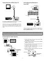
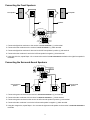
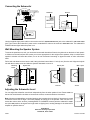
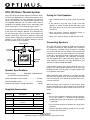
Cat. No.
31-3044
HTS-105 Home Theater System
Your HTS-105 Home Theater System includes the STAV3770 receiver (RadioShack 31-3042, with its owner’s manual and accessories), two front speakers, two surroundsound (rear) speakers, one center-channel speaker, and
one amplified subwoofer. All you need to add to have a
complete home theater system are an audio/video input
source (stereo Hi-Fi VCR or DVD/LD player) and a TV.
For receiver instructions and the HTS-105’s warranty, refer
to the STAV-3770 Owner’s Manual. The instructions on
the next few pages only cover basic home theater and
speaker connections, and how to adjust the subwoofer
controls. Before making any connections, see “Positioning
Speakers” in the STAV-3770 Owner’s Manual to choose
the best locations for your speakers.
Center Speaker
Front Left
Speaker
Front Right
Speaker
Subwoofer
Listening
Area
Rear Left
Speaker
Rear Right
Speaker
Power Handling .................. 35W RMS, 105W Maximum
(all speakers except subwoofer)
Nominal Impedance Front /Center ..................... 8 Ohms
Nominal Impedance Rear ................................. 16 Ohms
Sensitivity (all speakers except subwoofer) ........... 86 dB
Supplied Accessories
Description
• Use a polishing cloth or dry cloth to wipe off dust and
dirt.
• If the cabinet is very dirty, wipe it with a soft cloth
dipped in a neutral cleanser diluted with water, then
wipe again with a dry cloth. Do not use furniture wax
or cleaners.
• Never use thinner, benzene, insecticide sprays, or
other chemicals on or near the cabinets.
• Never use a vacuum cleaner to clean the grille cloth.
Connecting Speakers
Your HTS-105 system includes all speaker wires required
for speaker connections. Each speaker wire consists of
two conductors (individual wires) encased in insulation
and is color-coded so you can identify each conductor (the
color mark is on only one of the conductors in each speaker wire pair). Use these colors as a guide to help you properly connect the speakers. (For subwoofer connection,
use the supplied patch cable with phono plugs on both
ends. Phasing is automatic.) For easy identification, your
speakers are labeled FRONT and REAR.
If the supplied speaker wires are too short for your connections, you can purchase additional wire at your local
RadioShack store. Use 16-gauge (or larger) speaker wire
for all speaker connections.
Speaker Specifications
Quantity
Caring for Your Speakers
Colors
Speaker Wires
2
Receiver Out to Front Speakers
Light Blue/Pink
2
Receiver Out to Surround Sound
Speakers
Green/Orange
1
Receiver Out to Center Speaker
Yellow
Patch Cable
1
Receiver Out to Subwoofer (single cable)
1
VCR Out to Receiver In (dual cable)
When connecting each conductor to a speaker terminal,
hold down the terminal lever, insert the conductor’s end
into the small hole, and release the terminal lever to secure the conductor.
When connecting each conductor to the receiver, press
open the terminal lever, insert the conductor’s end into the
small hole, and press the lever closed to secure the conductor.
Notes:
• Be sure you connect the receiver’s right and left positive (+) and negative (–) terminals to the speaker’s
corresponding right and left positive (+) and negative
(–) terminals.
• Do not connect two pairs of speakers to a single set of
terminals.
• Surround speakers generally sound best if you position them above ear level.
© 1999 Tandy Corporation.
All Rights Reserved.
RadioShack and Optimus are registered trademarks used by Tandy Corporation.
Connecting Your Receiver to
Your VCR
Connecting Your VCR to Your TV
VIDEO
OUT
ANTENNA
IN
TO MONITOR TV
VIDEO
OUT
CONTROL
SUB
WOOFER
OUT
IN
IN
PLAY
OUT
REC
IN
VIDEO
IN
VIDEO
IN
PRE
OUT
IN
IN
PLAY
OUT
REC
L
L
R
R
PHONO
SIGNAL GND
TAPE2
MONITOR
CD
VCR/
TAPE1
DVD/
LD
REC
INPUT
L
OUT
R
IN
L
VCR
R
AUDIO
VIDEO
REC
PLAY
RF OUT
Double Patch Cable
PLAY
OUTPUT
R
L
If you have a VCR already connected to your TV, proceed
to “Connecting Your Receiver to Your VCR.”
ANTENNA
IN
ANTENNA
IN
VIDEO
AUDIO
REC
PLAY
VCR
Otherwise, connect your VCR’s ANTENNA OUT/RF OUT
jack to your TV’s ANTENNA IN/RF IN jack with a coaxial
antenna cable (one should have been supplied with your
VCR).
REC
INPUT
L
OUT
R
IN
PLAY
OUTPUT
Using the supplied double patch cable, connect the receiver’s VCR/TAPE1 IN PLAY jacks to your VCR’s AUDIO
PLAY or AUDIO OUT jacks.
See “Preparing Your Receiver” in the STAV-3770 Owner’s Manual to hook up four more external audio/video sources
(a CD player, for example) to your receiver.
Connecting the Center Speaker
1. Connect the yellow conductor to the receiver’s
TER SPEAKER (+) red terminal.
Center Speaker
CEN-
2. Connect the other conductor to the receiver’s CENTER
SPEAKER (–) black terminal.
3. Connect the yellow conductor’s other end to the center speaker’s positive (+) red terminal.
Yellow
4. Connect the other conductor’s end to the center
speaker’s negative (–) black terminal.
FRONT SPEAKERS
SUB
WOOFER
R
5. Attach the speaker stand’s protrusion to the center
hole on the center speaker.
L
CAUTION: SPEAKER IMPEDANCE
8
PRE
OUT
R
~ 16
/ SPEAKER
L
Center Hole
Speaker Stand’s
Protrusion
CENTER
SPEAKER
SURROUND
SPEAKERS
R
L
2
Connecting the Front Speakers
Front Speaker
Left
Right
Pink
Front Speaker
Light Blue
FRONT SPEAKERS
SUB
WOOFER
R
L
CAUTION: SPEAKER IMPEDANCE
8
PRE
OUT
R
L
R
L
CENTER
SPEAKER
~ 16
/ SPEAKER
SURROUND
SPEAKERS
1. Connect the light blue conductor to the receiver’s FRONT SPEAKERS L (+) red terminal.
2. Connect the other conductor to the receiver’s FRONT SPEAKERS L (–) black terminal.
3. Connect the light blue conductor’s other end to the left front speaker’s positive (+) red terminal.
4. Connect the other conductor’s end to the left front speaker’s negative (–) black terminal.
5. Using the pink wire, repeat Steps 1–4 to connect the receiver’s FRONT SPEAKERS R terminals to the right front speaker’s
terminals.
Connecting the Surround-Sound Speakers
FRONT SPEAKERS
SUB
WOOFER
R
L
CAUTION: SPEAKER IMPEDANCE
8
PRE
OUT
R
L
R
L
CENTER
SPEAKER
~ 16
/ SPEAKER
SURROUND
SPEAKERS
Green
Orange
Surround-Sound
Speaker
Surround-Sound
Speaker
Right
Left
1. Connect the green conductor to the receiver’s SURROUND SPEAKERS L (+) red terminal.
2. Connect the other conductor to the receiver’s SURROUND SPEAKERS L (–) black terminal.
3. Connect the green conductor’s other end to the left surround speaker’s positive (+) red terminal.
4. Connect the other conductor’s end to the left surround speaker’s negative (–) black terminal.
5. Using the orange wire, repeat Steps 1–4 to connect the right surround speaker to the receiver’s SURROUND SPEAKERS R
terminals.
3
Connecting the Subwoofer
FRONT SPEAKERS
SUB
WOOFER
R
L
CAUTION: SPEAKER IMPEDANCE
8
~ 16
/ SPEAKER
Subwoofer
PRE
OUT
R
Receiver
L
LINE LEVEL LEVEL
INPUT
POWER
MIN
CENTER
SPEAKER
MAX
SURROUND
SPEAKERS
R
L
AC OUTLET
AC 120V 60Hz
CAUTION:
DONOT CONNECT
TV SET OR MONITOR.
SWITCHED
100W MAX
0.8A MAX
LINE LEVEL LEVEL
INPUT
POWER
Subwoofer
MIN
MAX
Use the supplied single patch cable to connect the receiver’s SUBWOOFER/PRE OUT jack to the subwoofer’s LINE LEVEL INPUT
jack. Then connect the subwoofer’s power cord to a standard AC outlet or the receiver’s SWITCHED outlet. The subwoofer’s
POWER indicator lights when the power is on.
Wall Mounting the Speaker System
To mount the speakers on a wall, you need wood screws with heads that fit into the keyhole slot on the back of each speaker. Make sure the wall surface and screws you use are appropriate for the weight of the speakers. Keep in mind that the
speaker’s vibration will affect the surface, so we do not recommend mounting on plywood boards or other soft-surface
walls.
Drill a hole and thread a screw into the wall, letting the head extend about 1/4 inch (6 mm) from the wall. Align the keyhole
slot with the mounting screw and slide the speaker downward to secure it.
Mounting
Screw
Wall or pillar
Keyhole Slot
Wall or pillar
Gap
Incorrect
1/4"
Correct
Adjusting the Subwoofer Level
You can adjust the subwoofer sound level independently from the other speaker’s level. Rotate LEVEL on
the back of the subwoofer clockwise to increase the volume; counterclockwise to decrease it.
LINE LEVEL LEVEL
INPUT
POWER
MIN
MAX
Note: Always set to MIN before you begin listening, then increase the level slowly. If the system is turned
on with the volume set too high, it can cause damage to hearing or to the speaker. Take care not to increase the volume at the receiver (including BASS or LOUDNESS controls) with the subwoofer’s LEVEL
set at the MAX position: the signal level might reach a clipping level, causing damage to the subwoofer’s
amplifier or speaker element.
RadioShack
A Division of Tandy Corporation
Fort Worth, Texas 76102
06/99
Printed in the USA