1
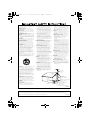
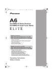
A6_KU.book 1 ページ 2006年11月13日 月曜日 午後3時1分 A6 SX-A6-J Stereo Receiver Register your product at: www.pioneerelectronics.com (US) www.pioneerelectronics.ca (Canada) • Protect your new investment The details of your purchase will be on file for reference in the event of an insurance claim such as loss or theft. • Receive free tips, updates and service bulletins on your new product • Improve product development Your input helps us continue to design products that meet your needs. • Receive a free Pioneer newsletter Registered customers can opt in to receive a monthly newsletter. Operating Instructions A6_KU.book 2 ページ 2006年11月13日 月曜日 午後3時1分 Location: rear of the unit CAUTION RISK OF ELECTRIC SHOCK DO NOT OPEN The lightning flash with arrowhead, within an equilateral triangle, is intended to alert the user to the presence of uninsulated "dangerous voltage" within the product's enclosure that may be of sufficient magnitude to constitute a risk of electric shock to persons. CAUTION: TO PREVENT THE RISK OF ELECTRIC SHOCK, DO NOT REMOVE COVER (OR BACK). NO USER-SERVICEABLE PARTS INSIDE. REFER SERVICING TO QUALIFIED SERVICE PERSONNEL. The exclamation point within an equilateral triangle is intended to alert the user to the presence of important operating and maintenance (servicing) instructions in the literature accompanying the appliance. D1-4-2-3_En IMPORTANT NOTICE – THE SERIAL NUMBER FOR THIS EQUIPMENT IS LOCATED IN THE REAR. PLEASE WRITE THIS SERIAL NUMBER ON YOUR ENCLOSED WARRANTY CARD AND D1-4-2-6-1_En KEEP IN A SECURE AREA. THIS IS FOR YOUR SECURITY. NOTE: This equipment has been tested and found to comply with the limits for a Class B digital device, pursuant to Part 15 of the FCC Rules. These limits are designed to provide reasonable protection against harmful interference in a residential installation. This equipment generates, uses, and can radiate radio frequency energy and, if not installed and used in accordance with the instructions, may cause harmful interference to radio communications. However, there is no guarantee that interference will not occur in a particular installation. If this equipment does cause harmful interference to radio or television reception, which can be determined by turning the equipment off and on, the user is encouraged to try to correct the interference by one or more of the following measures: – – – – Reorient or relocate the receiving antenna. Increase the separation between the equipment and receiver. Connect the equipment into an outlet on a circuit different from that to which the receiver is connected. Consult the dealer or an experienced radio/TV technician for help. D8-10-1-2_En Information to User Alteration or modifications carried out without appropriate authorization may invalidate the user’s right to operate the equipment. D8-10-2_En This Class B digital apparatus complies with Canadian ICES-003. Cet appareil numérique de la Classe B est conforme à la norme NMB-003 du Canada. WARNING – TO PREVENT FIRE OR SHOCK HAZARD, DO NOT EXPOSE THIS APPLIANCE TO RAIN OR MOISTURE. D1-4-2-1_En WARNING: Handling the cord on this product or cords associated with accessories sold with the product will expose you to chemicals listed on proposition 65 known to the State of California and other governmental entities to cause cancer and birth defect or other reproductive harm. Wash hands after handling D36-P4_A_En This product contains mercury. Disposal of this material may be regulated due to environmental considerations. For disposal or recycling information, please contact your local authorities or the Electronics K057_En Industries Alliance : www.eiae.org. D8-10-1-3_EF – PREVENT ELECTRIC SHOCK DO NOT USE THIS (POLARIZED) PLUG WITH AN EXTENSION CORD. RECEPTACLE OR OTHER OUTLET UNLESS THE BLADES CAN BE FULLY INSERTED TO PREVENT BLADE EXPOSURE. ATTENTION – POUR PREVENIR LES CHOCS ELECTRIQUES NE PAS UTILISER CETTE FICHE POLARISEE AVEC UN PROLONGATEUR UNE PRISE DE COURANT OU UNE AUTRE SORTIE DE COURANT, SAUF SI LES LAMES PEUVENT ETRE INSEREES A FOND SANS EN LAISSER AUCUNE PARTIE D2-4-4-1_EF A DECOUVVERT. CAUTION A6_KU.book 3 ページ 2006年11月13日 月曜日 午後3時1分 READ INSTRUCTIONS — All the safety and operating instructions should be read before the product is operated. RETAIN INSTRUCTIONS — The safety and operating instructions should be retained for future reference. HEED WARNINGS — All warnings on the product and in the operating instructions should be adhered to. FOLLOW INSTRUCTIONS — All operating and use instructions should be followed. CLEANING — The product should be cleaned only with a polishing cloth or a soft dry cloth. Never clean with furniture wax, benzine, insecticides or other volatile liquids since they may corrode the cabinet. ATTACHMENTS — Do not use attachments not recommended by the product manufacturer as they may cause hazards. WATER AND MOISTURE — Do not use this product near water — for example, near a bathtub, wash bowl, kitchen sink, or laundry tub; in a wet basement; or near a swimming pool; and the like. ACCESSORIES — Do not place this product on an unstable cart, stand, tripod, bracket, or table. The product may fall, causing serious injury to a child or adult, and serious damage to the product. Use only with a cart, stand, tripod, bracket, or table recommended by the manufacturer, or sold with the product. Any mounting of the product should follow the manufacturer’s instructions, and should use a mounting accessory recommended by the manufacturer. CART — A product and cart combination should be moved with care. Quick stops, excessive force, and uneven surfaces may cause the product and cart combination to overturn. VENTILATION — Slots and openings in the cabinet are provided for ventilation and to ensure reliable operation of the product and to protect it from overheating, and these openings must not be blocked or covered. The openings should never be blocked by placing the product on a bed, sofa, rug, or other similar surface. This product should not be placed in a built-in installation such as a bookcase or rack unless proper ventilation is provided or the manufacturer’s instructions have been adhered to. POWER SOURCES — This product should be operated only from the type of power source indicated on the marking label. If you are not sure of the type of power supply to your home, consult your product dealer or local power company. LOCATION – The appliance should be installed in a stable location. NONUSE PERIODS – The power cord of the appliance should be unplugged from the outlet when left un-used for a long period of time. GROUNDING OR POLARIZATION • If this product is equipped with a polarized alternating current line plug (a plug having one blade wider than the other), it will fit into the outlet only one way. This is a safety feature. If you are unable to insert the plug fully into the outlet, try reversing the plug. If the plug should still fail to fit, contact your electrician to replace your obsolete outlet. Do not defeat the safety purpose of the polarized plug. • If this product is equipped with a three-wire grounding type plug, a plug having a third (grounding) pin, it will only fit into a grounding type power outlet. This is a safety feature. If you are unable to insert the plug into the outlet, contact your electrician to replace your obsolete outlet. Do not defeat the safety purpose of the grounding type plug. POWER-CORD PROTECTION — Power-supply cords should be routed so that they are not likely to be walked on or pinched by items placed upon or against them, paying particular attention to cords at plugs, convenience receptacles, and the point where they exit from the product. OUTDOOR ANTENNA GROUNDING — If an outside antenna or cable system is connected to the product, be sure the antenna or cable system is grounded so as to provide some protection against voltage surges and built-up static charges. Article 810 of the National Electrical Code, ANSI/NFPA 70, provides information with regard to proper grounding of the mast and supporting structure, grounding of the lead-in wire to an antenna discharge unit, size of grounding conductors, location of antenna-discharge unit, connection to grounding electrodes, and requirements for the grounding electrode. See Figure A. LIGHTNING — For added protection for this product during a lightning storm, or when it is left unattended and unused for long periods of time, unplug it from the wall outlet and disconnect the antenna or cable system. This will prevent damage to the product due to lightning and power-line surges. POWER LINES — An outside antenna system should not be located in the vicinity of overhead power lines or other electric light or power circuits, or where it can fall into such power lines or circuits. When installing an outside antenna system, extreme care should be taken to keep from touching such power lines or circuits as contact with them might be fatal. OVERLOADING — Do not overload wall outlets, extension cords, or integral convenience receptacles as this can result in a risk of fire or electric shock. OBJECT AND LIQUID ENTRY — Never push objects of any kind into this product through openings as they may touch dangerous voltage points or short-out parts that could result in a fire or electric shock. Never spill liquid of any kind on the product. SERVICING — Do not attempt to service this product yourself as opening or removing covers may expose you to dangerous voltage or other hazards. Refer all servicing to qualified service personnel. DAMAGE REQUIRING SERVICE — Unplug this product from the wall outlet and refer servicing to qualified service personnel under the following conditions: • When the power-supply cord or plug is damaged. • If liquid has been spilled, or objects have fallen into the product. • If the product has been exposed to rain or water. • If the product does not operate normally by following the operating instructions. Adjust only those controls that are covered by the operating instructions as an improper adjustment of other controls may result in damage and will often require extensive work by a qualified technician to restore the product to its normal operation. • If the product has been dropped or damaged in any way. • When the product exhibits a distinct change in performance — this indicates a need for service. REPLACEMENT PARTS — When replacement parts are required, be sure the service technician has used replacement parts specified by the manufacturer or have the same characteristics as the original part. Unauthorized substitutions may result in fire, electric shock, or other hazards. SAFETY CHECK — Upon completion of any service or repairs to this product, ask the service technician to perform safety checks to determine that the product is in proper operating condition. WALL OR CEILING MOUNTING — The product should not be mounted to a wall or ceiling. HEAT — The product should be situated away from heat sources such as radiators, heat registers, stoves, or other products (including amplifiers) that produce heat. ANTENNA LEAD IN WIRE GROUND CLAMP ANTENNA DISCHARGE UNIT (NEC SECTION 810-20) ELECTRIC SERVICE EQUIPMENT Fig. A GROUNDING CONDUCTORS (NEC SECTION 810-21) GROUND CLAMPS POWER SERVICE GROUNDING ELECTRODE SYSTEM (NEC ART 250, PART H) NEC — NATIONAL ELECTRICAL CODE D1-4-2-2_En CAUTION: This product satisfies FCC regulations when shielded cables and connectors are used to connect the unit to other equipment. To prevent electromagnetic interference with electric appliances such as radios and televisions, use shielded cables and connectors for connections. D8-10-3a_En A6_KU.book 4 ページ 2006年11月13日 月曜日 午後3時1分 We Want You Listening For A Lifetime Selecting fine audio equipment such as the unit you’ve just purchased is only the start of your musical enjoyment. Now it’s time to consider how you can maximize the fun and excitement your equipment offers. This manufacturer and the Electronic Industries Association’s Consumer Electronics Group want you to get the most out of your equipment by playing it at a safe level. One that lets the sound come through loud and clear without annoying blaring or distortion-and, most importantly, without affecting your sensitive hearing. Sound can be deceiving. Over time your hearing “comfort level” adapts to higher volumes of sound. So what sounds “normal” can actually be loud and harmful to your hearing. Guard against this by setting your equipment at a safe level BEFORE your hearing adapts. Used wisely, your new sound equipment will provide a lifetime of fun and enjoyment. Since hearing damage from loud noise is often undetectable until it is too late, this manufacturer and the Electronic Industries Association’s Consumer Electronics Group recommend you avoid prolonged exposure to excessive noise. This list of sound levels is included for your protection. Decibel Level Example 30 40 50 60 70 80 Quiet library, soft whispers Living room, refrigerator, bedroom away from traffic Light traffic, normal conversation, quiet office Air conditioner at 20 feet, sewing machine Vacuum cleaner, hair dryer, noisy restaurant Average city traffic, garbage disposals, alarm clock at two feet. THE FOLLOWING NOISES CAN BE DANGEROUS UNDER CONSTANT EXPOSURE To establish a safe level: • Start your volume control at a low setting. • Slowly increase the sound until you can hear it comfortably and clearly, and without distortion. 90 Subway, motorcycle, truck traffic, lawn mower 100 Garbage truck, chain saw, pneumatic drill 120 Rock band concert in front of speakers, thunderclap 140 Gunshot blast, jet plane 180 Rocket launching pad Once you have established a comfortable sound level: • Set the dial and leave it there. Information courtesy of the Deafness Research Foundation. Taking a minute to do this now will help to prevent hearing damage or loss in the future. After all, we want you listening for a lifetime. S001_En For U.S. and Australia Model C67-7-3_En " Perchlorate Material – special handling may apply. See www.dtsc.ca.gov/hazardouswaste/perchlorate. (Applicable to California, U.S.A.) " POWER-CORD CAUTION Handle the power cord by the plug. Do not pull out the plug by tugging the cord and never touch the power cord when your hands are wet as this could cause a short circuit or electric shock. Do not place the unit, a piece of furniture, etc., on the power cord, or pinch the cord. Never make a knot in the cord or tie it with other cords. The power cords should be routed such that they are not likely to be stepped on. A damaged power cord can cause a fire or give you an electrical shock. Check the power cord once in a while. When you find it damaged, ask your nearest PIONEER authorized service center or your dealer for a replacement. S002_En This product is for general household purposes. Any failure due to use for other than household purposes (such as long-term use for business purposes in a restaurant or use in a car or ship) and which requires repair will be charged for even during the K041_En warranty period. A6_KU.book 5 ページ 2006年11月13日 月曜日 午後3時1分 Thank you for buying this Pioneer product. Please read through these operating instructions so that you will know how to operate your model properly. After you have finished reading the instructions, put them in a safe place for future reference. Contents 01 Before you start 05 Using the tuner Features . . . . . . . . . . . . . . . . . . . . . . . . . . . . . 6 What’s in the box . . . . . . . . . . . . . . . . . . . . . . 6 Inserting the battery . . . . . . . . . . . . . . . . . . . 7 Installing the receiver . . . . . . . . . . . . . . . . . . . 7 Listening to the radio . . . . . . . . . . . . . . . . . . . 15 Saving station presets . . . . . . . . . . . . . . . . . . 15 Naming station presets . . . . . . . . . . . . . . . . 15 Listening to station presets . . . . . . . . . . . . . 15 02 Connecting up 06 Other connections Making cable connections . . . . . . . . . . . . . . . 8 Connecting audio components . . . . . . . . . . . . 8 Connecting antennas . . . . . . . . . . . . . . . . . . . 9 Using external antennas . . . . . . . . . . . . . . . . 9 Connecting the speakers. . . . . . . . . . . . . . . . 10 Plugging in . . . . . . . . . . . . . . . . . . . . . . . . . . 10 Using XM Radio. . . . . . . . . . . . . . . . . . . . . . . 17 Connecting your XM Radio receiver . . . . . . 17 Listening to XM Radio . . . . . . . . . . . . . . . . . 17 Saving channel presets . . . . . . . . . . . . . . . . 18 Connecting an IR receiver . . . . . . . . . . . . . . . 19 Operating other Pioneer components with this unit’s sensor . . . . . . . . . . . . . . . . . . . . . . . . . 19 Switching components on and off using the 12 volt trigger. . . . . . . . . . . . . . . . . . . . . . . . . 20 03 Controls and displays Front panel . . . . . . . . . . . . . . . . . . . . . . . . . . 11 Remote control . . . . . . . . . . . . . . . . . . . . . . . 12 Using the remote control . . . . . . . . . . . . . . 12 Display . . . . . . . . . . . . . . . . . . . . . . . . . . . . . 13 04 Listening to your system Using Direct listening . . . . . . . . . . . . . . . . . . 14 Using the balance and tone controls. . . . . . . 14 Playing other sources . . . . . . . . . . . . . . . . . . 14 Making an audio recording . . . . . . . . . . . . . . 14 07 Additional information Troubleshooting. . . . . . . . . . . . . . . . . . . . . . . 21 XM radio messages. . . . . . . . . . . . . . . . . . . 22 Specifications . . . . . . . . . . . . . . . . . . . . . . . . 22 Cleaning the unit. . . . . . . . . . . . . . . . . . . . . 23 A6_KU.book 01 6 ページ 2006年11月13日 月曜日 午後3時1分 Before you start Chapter 1: Before you start Features • Quick response power supply circuit The superior power supply circuit adopted by this unit achieves vastly improved response by employing ‘no feedback’ circuitry and low impedence parallel main capacitors characteristicly used in professional audio monitoring. • Twin-mono symmetrical construction This receiver offers a new advancement in stereo imaging with the completely independent construction of left/right power amplification units and twin transformers. • Direct construction In addition to the improved symmetrical design, the signal path of each block is designed for shortest signal path for minimum deterioration of signal clarity. • Wide-Range Linear Circuit Through this proprietary feedback circuit, an output signal of low impedance offering a flat, even response over the widest possible frequency range is delivered to your speakers. • XM Radio ready The XM Radio terminal on this receiver provides a quick and easy connection to XM Radio, the leading provier of satellite radio service in the United States. Visit www.xmradio.com for more details on this service. 6 En • Fine-tuned to world-class standards With the cooperation of the world-class studio engineers at AIR Studios, this receiver has been AIR Studios certified: What’s in the box Please confirm that the following accessories are in the box when you open it. • Remote control • Lithium battery (CR2025) • AM loop antenna • FM wire antenna • Power cable • Operating instructions • Warranty card A6_KU.book 7 ページ 2006年11月13日 月曜日 午後3時1分 Before you start Inserting the battery Insert the lithium battery (CR2025) into the remote control as shown below. The battery supplied with this unit is stored in the battery casing (see step 3 below). When you notice a decrease in the operating range, replace the battery in the same manner. 2 4 1 3 1 Push the release tab to the right to open the battery casing. 2 Pull out the battery casing. 3 Remove the battery from the casing. If you're doing this for the first time, remove the protective seal from the battery supplied with the system before re-inserting it. 4 Place a new battery in the casing. Make sure the side of the battery is facing up when you place it in the space provided. Caution When using lithium batteries, please observe the following: • There is danger of explosion if the battery is incorrectly replaced. Make sure to replace only with the same or equivalent type recommended by the manufacturer. 01 • Lithium batteries may present a fire or chemical burn hazard if misused. Do not disassemble, heat above 100°C (212°F), or incinerate. • Remove the battery if the unit isn’t going to be used for a month or more. • When disposing of used batteries, please comply with governmental regulations or environmental public instruction’s rules that apply in your country or area. • Do not use or store batteries in direct sunlight or other excessively hot place, such as inside a car or near a heater. This can cause batteries to leak, overheat, explode or catch fire. It can also reduce the life or performance of batteries. Installing the receiver • When installing this unit, make sure to put it on a level and stable surface. Don’t install it on the following places: – on a color TV (the screen may distort) – near a cassette deck (or close to a device that gives off a magnetic field). This may interfere with the sound. – in direct sunlight – in damp or wet areas – in extremely hot or cold areas – in places where there is vibration or other movement – in places that are very dusty – in places that have hot fumes or oils (such as a kitchen) • Dispose of used battery cells immediately after replacement. Keep away from children. • If swallowed, please contact a doctor immediately. 7 En A6_KU.book 02 8 ページ 2006年11月13日 月曜日 午後3時1分 Connecting up Chapter 2: Connecting up 3 Making cable connections Make sure not to bend the cables over the top of this unit (as shown in the illustration). If this happens, the magnetic field produced by the transformers in this unit may cause a humming noise from the speakers. Turntable FM UNBAL 75 AM LOOP ANTENNA CONTROL OUT IR XM IN IN OUT L REC OUT 12V TRIGGER L R R PLAY IN AUX1 TAPE SIGNAL GND AUX2 CD PHONO This receiver L Important 2 IN • Before making or changing any connections, switch off the power and disconnect the power cord from the AC outlet. REC OUT PLAY AUDIO IN/OUT The number and kind of connections depends on the kind of component you’re connecting. Follow the steps below to connect a CD player, tape recorder, turntable or other audio component. CD player, etc. • Connect any other components (such as an iPod1 dock or a portable audio player) to the AUX inputs in the same way. Note En L 1 Connect the analog audio outputs of your CD player (or other component) to the CD inputs on this receiver. Use a stereo RCA phono cable as shown. 1 iPod is a trademark of Apple Computer, Inc., registered in the U.S. and other countries. 8 R AUDIO OUT D6 Tape deck, etc. Connecting audio components 1 OUT R A6_KU.book 9 ページ 2006年11月13日 月曜日 午後3時1分 Connecting up 02 2 Connect the analog outputs of your tape deck (or other recorder) to the TAPE inputs (IN) on this receiver. Then connect the audio inputs on the tape deck to the TAPE outputs (OUT) on this receiver. This will allow you to make recordings from the components connected to this receiver. Use stereo RCA phono cables as shown. 3 Turntables only: Connect the audio outputs of your turntable to the PHONO inputs on this receiver. • If your turntable has a grounding wire, secure it to the ground terminal on this receiver. • If your turntable has line-level outputs (i.e., it has a built-in phono pre-amp), connect it to the AUX inputs instead. 3 Fix the AM loop antenna to the attached stand. To fix the stand to the antenna, bend in the direction indicated by the arrow then clip the loop onto the stand (fig. a). • If you plan to mount the AM antenna to a wall or other surface, secure the stand with screws (fig. b) before clipping the loop to the stand. Make sure the reception is clear. 4 Place the AM antenna on a flat surface and in a direction giving the best reception. 5 Connect the FM wire antenna in the same way as the AM loop antenna. For best results, extend the FM antenna fully and fix to a wall or door frame. Don’t drape loosely or leave coiled up. Using external antennas Connecting antennas To improve FM reception Connect the AM loop antenna and the FM wire antenna as shown below. To improve reception and sound quality, connect external antennas (see Using external antennas below). fig. a Use a 75 Ω coaxial cable to connect an external FM antenna. fig. b One-touch PAL connector AM LOOP ANTENNA To improve AM reception ANTENNA 5 4 1 AM LOOP 75 Ω coaxial cable 3 FM UNBAL 75 FM UNBAL 75 2 Connect a 5 m to 6 m (15 ft. to 18 ft.) length of vinyl-coated wire to the AM antenna terminal without disconnecting the supplied AM loop antenna. Outdoor antenna 5 m to 6 m (15 ft. to 18 ft.) 1 Pull off the protective shields of both AM antenna wires. 2 Push open the tabs, then insert one wire fully into each terminal, then release the tabs to secure the AM antenna wires. Indoor antenna (vinyl-coated wire) FM UNBAL 75 AM LOOP ANTENNA For the best possible reception, suspend horizontally outdoors. 9 En A6_KU.book 02 10 ページ 2006年11月13日 月曜日 午後3時1分 Connecting up Connecting the speakers Make sure you connect the speaker on the right to the right terminal and the speaker on the left to the left terminal. Also make sure the positive and negative (+/–) terminals on the receiver match those on the speakers. You can use speakers with a nominal impedance between 4 Ω–16 Ω. To connect a terminal, unscrew the terminal a few turns until there is enough space to insert the exposed wire (fig. B). Once the wire is in position, tighten the terminal until the wire is firmly clamped (fig. C). fig. A fig. B fig. C 3 /8 in. Be sure to complete all connections before connecting this unit to the AC power source. Left speaker Important • Please refer to the manual that came with your speakers for details on how to connect the other end of the speaker cables to your speakers. CONTROL OUT OUT Caution SIGNAL GND AC IN L SPEAKER L R PHONO • Connect the speakers to the speaker terminals as shown above. Connections for the left speaker are shown. Connect the right speaker in the same way. You can use either bare wire connections or banana plugs to do this (see below). 10 En • These speaker terminals carry HAZARDOUS live voltage. To prevent the risk of electric shock when connecting or disconnecting the speaker cables, disconnect the power cord before touching any uninsulated parts. • Make sure no exposed speaker wire is touching the rear panel, this may cause the receiver to turn off automatically. Bare wire connections Plugging in Make sure that the speaker cable you’re going to use is properly prepared with about 3/8 inch of insulator stripped from each wire, and the exposed wire strands twisted together (fig. A). Make sure to complete all connections before connecting to an AC outlet. • Connect the AC power cord to the AC IN inlet on the rear panel of the receiver, then plug into a power outlet. A6_KU.book 11 ページ 2006年11月13日 月曜日 午後3時1分 Controls and displays 03 Chapter 3: Controls and displays Front panel 1 2 4 3 5 6 STEREO RECEIVER A6 INPUT SELECTOR VOLUME POWER STANDBY OFF 7 ON DIRECT PHONES 8 1 POWER OFF ON 2 STANDBY indicator 3 Character display (page 13) 4 DIRECT Press to switch the Direct listening feature on or off (page 14). 5 INPUT SELECTOR dial Selects an input source. 6 MASTER VOLUME 7 Remote sensor 8 PHONES jack Use to connect headphones (when connected, there is no sound output from the speakers). 11 En A6_KU.book 03 12 ページ 2006年11月13日 月曜日 午後3時1分 Controls and displays 8 VOLUME +/– Use to set the listening volume. Remote control 9 MUTE Mutes/unmutes the sound. DIMMER 6 10 Tuner and XM Radio controls DISPLAY (XM Radio only) – Switches between named station presets and radio frequencies (page 15). DIRECT 7 BAND (Tuner only) – Switches between the AM and FM bands (page 15). VOL 8 9 CATEGORY (XM Radio only) – Press to browse digital radio broadcasts (page 17). 1 2 CD TAPE PHONO AUX1 AUX2 TUNER XM TONE/BAL 3 4 10 5 L/ R/ 1 2 3 4 5 6 MUTE 7 8 9 0 DISPLAY BAND TUNE ST CATEGORY D.ACCESS MPX ST ENTER TUNE T.EDIT RETURN 10 CLASS STEREO RECEIVER MPX (Tuner only) – Switches between stereo and mono reception of FM broadcasts (page 15). D.ACCESS – Press to access a radio station directly using the number buttons (page 15). T.EDIT – Memorizes/names stations for recall (page 15). CLASS – Switches between the three banks of radio station presets (page 15). 1 Switches the receiver between standby and on. 2 Input selector buttons Press to select an input source. 3 TONE/BAL controls Use to adjust the tone and balance (page 14). 4 Number buttons Use the number buttons to directly select a radio frequency (page 15). 5 (TUNE/ST) /ENTER Use the TUNE +/– buttons to find radio frequencies and use ST +/– to find preset stations (page 15). 6 DIMMER Dims or brightens the display (or switches the backlight off). 7 DIRECT Press to access Direct listening (page 14). 12 En RETURN (XM Radio only) – Press to confirm and exit the current menu. Using the remote control Keep in mind the following when using the remote control: • Make sure that there are no obstacles between the remote and the remote sensor on the unit. • The remote has a range of about 7 m (23 ft.) at an angle of about 30º from the remote sensor. • Remote operation may become unreliable if strong sunlight or fluorescent light is shining on the unit’s remote sensor. • Remote controllers for different devices can interfere with each other. Avoid using remotes for other equipment located close to this unit. A6_KU.book 13 ページ 2006年11月13日 月曜日 午後3時1分 Controls and displays 03 • Replace the batteries when you notice a fall off in the operating range of the remote. Display 1 2 TUNED STEREO MONO 3 TREBLE BASS dB XM FM AM 4 1 MHz KHz 5 6 7 Tuner Indicators TUNED – Lights when a broadcast is being received. STEREO – Lights when a stereo FM broadcast is being received in auto stereo mode. MONO – Lights when the MPX button is used to select mono mode. 2 Tone control indicators TREBLE - Lights when high-range tone adjustment is applied. BASS - Lights when low-range tone adjustment is applied. 3 Master volume level 4 FM – Lights when FM broadcasts are received. AM – Lights when AM broadcasts are received. 5 XM – Lights when XM radio broadcasts are received. 6 Character display Displays various system information. 7 MHz – Lights when an FM frequency is displayed. KHz – Lights when an AM frequency is displayed. 13 En A6_KU.book 04 14 ページ 2006年11月13日 月曜日 午後3時1分 Listening to your system Chapter 4: Listening to your system Using Direct listening Use the Direct listening feature when you want to hear the truest possible reproduction of a source. All unnecessary signal processing1 is bypassed, and you’re left with the pure sound source. • While listening to a source, press DIRECT to switch Direct listening on or off. Using the balance and tone controls Playing other sources 1 Turn on the power of the playback component. 2 Turn on the power of the receiver. 3 Select the source you want to playback. Use the input select buttons (or INPUT SELECTOR dial). 4 Start playback of the component you selected in step 1. Depending on what you are listening to, you may want to adjust the bass, treble or left/right balance using the remote control. Making an audio recording 1 Press TONE/BAL to select the option you want, then use the L/– and R/+ buttons to adjust as necessary. • BASS – Adjust the amount of bass from –10 to +10. 1 Select the source you want to record. Use the input select buttons (INPUT SELECTOR). • TRE – Adjust the amount of treble from –10 to +10. • BAL – Adjust the amount of left/right balance as you like. FLAT indicates a centered balance. Wait about five seconds for your changes to be input automatically. The BASS and TREBLE indicators light in the front panel when the corresponding tone control is active. You can make an audio recording from any audio source connected to the receiver. 2 Prepare the source you want to record. Tune to the radio station, load the CD, set up the turntable, etc. 3 Prepare the recorder. Insert a blank tape, MD, etc. into the recording device and set the recording levels.2 Refer to the instructions that came with the recorder if you are unsure how to do this. 4 Start recording, then start playback of the source component. • To return to the flat setting (tone control off), press L/– and R/+ at the same time. Note 1 The balance and tone controls are disabled, and the front panel display switches off. 2 The receiver's volume, balance and tone controls have no effect on the recorded signal. 14 En A6_KU.book 15 ページ 2006年11月13日 月曜日 午後3時1分 Using the tuner 05 Chapter 5: Using the tuner Listening to the radio The following steps show you how to tune in to FM and AM radio broadcasts. 1 Press TUNER then press BAND to select the tuner band. 2 Tune to a station. There are four ways to do this: Automatic tuning – Press and hold TUNE +/– for about a second. Searching automatically stops at the next station. Manual tuning – To change the frequency one step at a time, press TUNE +/–. High speed tuning – Press and hold TUNE +/– continuously. 2 Press CLASS to select one of the three classes then press ST +/– to select the station preset you want. 3 Press ENTER to store the station. Naming station presets You can your station presets for easy recall. 1 Choose the preset you want to name. See Listening to station presets below. 2 Press T.EDIT. A cursor appears at the first character position. 3 Input the name you want then press ENTER. Names can be up to four characters long. • Use the ST +/– buttons to select characters, and ENTER to confirm. If no character is input, a space is input. Direct access – Use the number buttons to enter the frequency (For example, to tune to 106.00 (FM), press 1, 0, 6, 0, 0).1 Tip If the TUNED or STEREO indicators don't light when tuning to an FM station because the signal is weak, press the MPX button to switch the receiver into mono reception mode. This should improve the sound quality and allow you to enjoy the broadcast. • Once you have named a station preset, you can press DISPLAY when listening to a station to switch the display between the name and the frequency. Listening to station presets Saving station presets This receiver can memorize up to 30 stations, stored in three banks of 10 stations each.2 1 Tune to a station you want to memorize then press T.EDIT. The display shows ST. MEMORY, then a blinking memory class. You will need to have some presets stored to do this. See Saving station presets above if you haven’t done this already.3 1 Press TUNER to select the tuner. Note 1 If you make a mistake halfway through, press D.ACCESS twice to cancel the frequency and start over. 2 When saving an FM frequency, the MPX setting is also stored. 3 Station memories will be lost if the receiver is left disconnected from the AC power outlet for an extended period. 15 En A6_KU.book 05 16 ページ 2006年11月13日 月曜日 午後3時1分 Using the tuner 2 Press CLASS to select the class in which the station is stored. Press repeatedly to cycle through classes A, B and C. 3 Press ST +/– to select the station preset you want. 16 En A6_KU.book 17 ページ 2006年11月13日 月曜日 午後3時1分 Other connections 06 Chapter 6: Other connections Using XM Radio XM is the leading provider of satellite radio in the United States. Through two high-power satellites, Rock and Roll, XM Radio service offers over 150 channels of music, news, talk, sports and children's programming on a monthly subscription basis. XM Radio offers consumers clear sound quality from digital signal radio, an extensive variety of programming and nationwide coverage. Visit www.xmradio.com for more details on this service. Connecting your XM Radio receiver After purchasing a Connect-and Play™ antenna (sold separately), you will also need to activate the XM Radio digital radio service to receive broadcasts.1 1 Connect an XM Radio Connect-and-Play™ antenna to the XM Radio jack on the rear of this receiver. You will also need to activate the XM Radio service. When activating the XM Radio ‘Connect-andPlay’ ™ digital antenna, make sure to wait until the activation process is complete before changing the XM-RADIO function. Changing to another input source will stop the activation process. 2 Use the XM input selector button to switch to the XM Radio input. For best reception, you may need to move the Connect-and-Play™ antenna near a window (the southernmost window should produce the best results). • If after pressing XM the display shows ANTENNA, try disconnecting the antenna and reconnecting.2 Listening to XM Radio After connecting, you will be able to use this receiver to select channels and navigate categories using the front panel display. Connect-and-Play antenna IN Selecting channels and browsing by genre CONTROL OUT IR XM IN OUT L SIGNAL GND AC IN L SPEAKER R R AUX2 CD L You can browse XM Radio channels in the order that they appear, or you can narrow your channel search by genre. PHONO This receiver Note 1 Hardware and required basic monthly subscription sold separately. Premium Channel available at additional monthly cost. Installation costs and other fees and taxes, including a one-time activation fee may apply. Subscription fee is consumer only. All fees and programming subject to change. Channels with frequent explicit language are indicated with an XL. Channel blocking is available for XM radio receivers by calling 1-800-XMRADIO. Subscriptions subject to Customer Agreement available at xmradio.com. Only available in the 48 contiguous United States. 2 After unplugging the receiver, LOADING shows in the display for about 1 minute when switched back on. 17 En A6_KU.book 06 18 ページ 2006年11月13日 月曜日 午後3時1分 Other connections • Use the / buttons to select a channel then press ENTER to listen to the XM radio broadcast. • To browse by genre, first press CATEGORY, use / to select a genre then press ENTER.1 • To cancel and exit any time, press RETURN. Tip • You can select channels directly by pressing D.ACCESS then the three-digit channel number. 1 Press CLASS to select the class in which the channel is stored. Press repeatedly to cycle through classes A, B and C. 2 Press / to select the channel preset you want. • You can also use the number buttons on the remote control to recall the channel preset. Connect & Play™, XM-Ready® and The Ultimate Playlist are trademarks of XM Satellite Radio Inc. ©2005 XM Satellite Radio Inc. All rights reserved. All other trademarks are the property of their respective owners. • You can press DISPLAY to change XM Radio information in the front panel display. Saving channel presets This receiver can memorize up to 30 channels, stored in three banks, or classes, (A, B and C) of 10 stations each. 1 Select the channel you want to memorize. See Selecting channels and browsing by genre above. 2 Press T.EDIT. The display shows a blinking memory class. 3 Press CLASS to select one of the three classes then press / to select the channel preset you want. You can also use the number buttons to select a preset. • The default for all presets is CH001. 4 Press ENTER. After pressing ENTER, the preset class and number stop blinking and the receiver stores the XM channel. Listening to channel presets You will need to have some presets stored to do this. Note 1 Select CH000 (RADIO ID) from the front panel display to check the Radio ID of the Connect-and-Play antenna. 18 En A6_KU.book 19 ページ 2006年11月13日 月曜日 午後3時1分 Other connections 06 Connecting an IR receiver If you keep your stereo components in a closed cabinet or shelving unit, you can use an optional IR receiver (such as a Niles or Xantech unit) to control your system instead of the remote sensor on the front panel of this receiver.1 1 Connect the IR receiver sensor to the IR IN jack on the rear of this receiver. Closet or shelving unit Non-Pioneer component IR IN Pioneer component CONTROL IN OUT IN Pioneer component R L MM/MC CD 1 Connect the CONTROL OUT of this receiver to the CONTROL IN jack of another Pioneer component. Use a cable with a mono mini-plug on each end for the connection. This receiver SIGNAL GND L AUX2 • Note that if you use this feature, make sure that you also have at least one set of analog audio jacks connected to another component for grounding purposes. OUT R AUX1 Many Pioneer components have SR CONTROL jacks which can be used to link components together so that you can use just the remote sensor of one component. When you use a remote control, the control signal is passed along the chain to the appropriate component. CONTROL OUT IR XM IN Operating other Pioneer components with this unit’s sensor PHONO This receiver Pioneer component remote control CONTROL OUT IR IN IR receiver L 2 Connect the IR IN jack of another component to the IR OUT jack on the rear of this receiver to link it to the IR receiver. Please see the manual supplied with your IR receiver for the type of cable necessary for the connection. • If you want to link a Pioneer component to the IR receiver, see Operating other Pioneer components with this unit’s sensor below to connect to the CONTROL jacks instead of the IR OUT jack. CONTROL OUT OUT SIGNAL GND 2 If the Pioneer component also has a CONTROL OUT jack, you can continue the chain in the same way for as many components as you have. Note 1 • Remote operation may not be possible if direct light from a strong fluorescent lamp is shining on the IR receiver remote sensor window. • Note that other manufacturers may not use the IR terminology. Refer to the manual that came with your component to check for IR compatibility. • If using two remote controls (at the same time), the IR receiver’s remote sensor takes priority over the remote sensor on the front panel. 19 En A6_KU.book 06 20 ページ 2006年11月13日 月曜日 午後3時1分 Other connections Switching components on and off using the 12 volt trigger You can connect components in your system to this receiver through a 12 volt trigger. If you turn the power to a connected component on, the power to this receiver is also turned on. This receiver will not turn on if you turn a connected component off while this receiver is currently off.1 12V TRIGGER FM UNBAL 75 SPEAKER R 12V TRIGGER • Connect the 12V TRIGGER jack of this receiver to the 12V trigger of another component. Use a cable with a mono mini-plug on each end for the connection. Note 1 When this system is already on, switching the connected component on will have no effect (switching the connected component off will have no effect in any case). 20 En A6_KU.book 21 ページ 2006年11月13日 月曜日 午後3時1分 Additional information 07 Chapter 7: Additional information Troubleshooting Incorrect operations are often mistaken for trouble and malfunctions. If you think that there is something wrong with this component, check the points below. Sometimes the trouble may lie in another component. Investigate the other components and electrical appliances being used. If the trouble cannot be rectified even after exercising the checks listed below, ask your nearest Pioneer authorized service center or your dealer to carry out repair work. • If the unit does not operate normally due to external effects such as static electricity disconnect the power plug from the outlet and insert again to return to normal operating conditions. Problem Remedy The power does not turn on. • Disconnect the power plug from the outlet, and insert again. • Make sure there are no loose strands of speaker wire touching the rear panel. This could cause the receiver to shut off automatically. • If you’re trying to switch on using the remote control, make sure the front panel POWER button is switched on first. • If the power shuts off automatically, take the unit to your nearest Pioneer authorized service center or your dealer for servicing. No sound is output when a function is selected. • Make sure the component is connected correctly (refer to Connecting up on page 8). • Press MUTE on the remote control to turn muting off. Considerable noise in radio broadcasts. • Connect the antenna (page 9) and adjust the position for best reception. • Route any loose cables away from the antenna terminals and wires. • Fully extend the FM wire antenna, position for best reception, and secure to a wall (or connect an outdoor FM antenna). • Connect an additional internal or external AM antenna (page 9). • Turn off equipment causing interference or move it away from the receiver (or move antennas farther away from equipment causing noise). Broadcast stations cannot be selected automatically. • Connect an outdoor antenna (refer to page 9). Noise during playback of a cassette deck. • Move the cassette deck further from your receiver, until the noise disappears. Can’t operate the remote control. • Replace the battery (refer to page 7). • Operate within 7 m (23 ft.), 30° of the remote sensor on the front panel (refer to page 12). • Remove the obstacle or operate from another position. • Avoid exposing the remote sensor on the front panel to direct light. 21 En A6_KU.book 07 22 ページ 2006年11月13日 月曜日 午後3時1分 Additional information Problem Remedy The display is dark or off. • Press DIMMER on the remote repeatedly to return to the default. XM radio messages Message Cause Action ANTENNA The XM antenna is not connected. Check that the XM antenna cable is attached securely. ANT ERR A short-circuit occurring in the antenna or surrounding antenna cable. Make sure that there is nothing unusual with the antenna or antenna cable. Switch the power off then back on again. UPDATING The radio is being updated with the latest encryption code. Wait until the encryption code has been updated. Channels 00 and 01 should function normally. NO SIGNAL The XM signal is too weak at the current location. n/a LOADING The receiver is acquiring audio or program information. Wait until the information has been received. OFF AIR The channel currently selected has stopped broadcasting. Select another channel. CH – – – You have selected a channel that does not exist, or that you have not subscribed to. The receiver will automatically switch to channel 001 (or the last selected channel). There is no artist name/feature, song/ No action needed. program title, or channel category associated with the channel at this time. Specifications Amplifier section Power output specification is for when power supply is 120 V. • Continuous power output (both channels driven at 20 Hz to 20 kHz)** THD 0.2 % . . . . . . . . . . . . . . . . . . . . . 60 W + 60 W THD 0.2 % . . . . . . . . . . . . . . . . . . . . . 45 W + 45 W 22 En • FTC Continuous power output (both channels driven at 1 kHz) THD 1.0%, 4 Ω . . . . . . . . . . . . . . . . . 53 W + 53 W THD 1.0%, 8 Ω . . . . . . . . . . . . . . . . . 43 W + 43 W • Total harmonic distortion** 20 Hz to 20 kHz, 25 W, 8 Ω . . . . . . . . . . . . 0.05 %* * Measured with DIRECT button switched on. ** Measured by Audio Spectrum Analyzer A6_KU.book 23 ページ 2006年11月13日 月曜日 午後3時1分 Additional information Audio section • Input (Sensitivity/Impedance) • Frequency response CD, TAPE, AUX . . . . . . . . . . . . . . . .200 mV/47 kΩ PHONO (MM). . . . . . . . . . . . . . . . . . 2.8 mV/47 kΩ CD, TAPE, AUX . . . . . . . . . . . 5 Hz to 100 kHz dB PHONO (MM). . . . . . . . . 20 Hz to 20 kHz ±0.2 dB • PHONO (MM) overload level 1 kHz, THD 0.2 % . . . . . . . . . . . . . . . . . . . . . 60 mV • Output (Level/Impedance) • Tone control TAPE REC . . . . . . . . . . . . . . . . . . . . . . 200 mV/1 kΩ Bass . . . . . . . . . . . . . . . . . . . . . . ± 10 dB (100 Hz) Treble . . . . . . . . . . . . . . . . . . . . . ± 10 dB (10 kHz) • Signal-to-Noise Ratio CD, TAPE, AUX (200 mV input). . . . . . . . . . 103 dB PHONO (MM, 5 mV input) . . . . . . . . . . . . . . 80 dB • Miscellaneous Power requirements. . . . . . . . . . . AC 120 V, 60 Hz Power consumption . . . . . . . . . . . . . . . . . . . 170 W In standby . . . . . . . . . . . . . . . . . . . . . . . . . 0.6 W Dimensions . . . 420 mm (W) x 100 mm (H) x 359 mm (D) (16 9/16 in. (W) x 3 15/16 in. (H) x 14 1/8 in. (D)) Weight (without package) . . . . . . . . 10 kg (22 lb.) Accessories Remote control . . . . . . . . . . . . . . . . . . . . . . . . . . . Lithium battery (CR2025) . . . . . . . . . . . . . . . . . . . AM loop antenna . . . . . . . . . . . . . . . . . . . . . . . . . FM wire antenna. . . . . . . . . . . . . . . . . . . . . . . . . . Power cable. . . . . . . . . . . . . . . . . . . . . . . . . . . . . . Warranty card . . . . . . . . . . . . . . . . . . . . . . . . . . . . Operating instructions 1 1 1 1 1 1 Note • Specifications and the design are subject to possible modifications without notice, due to improvements. FM Tuner Section Frequency Range. . . . . . . . .87.5 MHz to 108 MHz Usable Sensitivity . . . . . . . . . Mono:13.2 dBf, IHF (1.3 µV/ 75 Ω) 50 dB Quieting Sensitivity. . . . . . . Mono: 20.2 dB Stereo: 38.6 dBf Signal-to-Noise Ratio. . . .Mono: 73 dB (at 85 dBf) Stereo: 70 dB (at 85 dBf) Distortion . . . . . . . . . . . . . . . Stereo: 0.5 % (1 kHz) Alternate Channel Selectivity . . . 60 dB (400 kHz) Stereo Separation . . . . . . . . . . . . . . 40 dB (1 kHz) Frequency Response . . . . . . . . . . .30 Hz to 15 kHz (±1 dB) Antenna Input (FTC) . . . . . . . . . 75 Ω unbalanced • 07 Cleaning the unit • Use a polishing cloth or dry cloth to wipe off dust and dirt. • When the surface is dirty, wipe with a soft cloth dipped in some neutral cleanser diluted five or six times with water, and wrung out well, and then wipe again with a dry cloth. Do not use furniture wax or cleansers. • Never use thinners, benzine, insecticide sprays or other chemicals on or near this unit, since these will corrode the surface. AM Tuner Section Frequency Range. . . . . . . . . .530 kHz to 1700 kHz Sensitivity (IHF, Loop antenna). . . . . . . . 350 µV/m Signal-to-Noise Ratio. . . . . . . . . . . . . . . . . . . 50 dB Antenna . . . . . . . . . . . . . . . . . . . . . . Loop antenna 23 En A6_KU.book 24 ページ 2006年11月15日 水曜日 午後1時41分 Should this product require service in the U.S.A. and you wish to locate the nearest Pioneer Authorized Independent Service Company, or if you wish to purchase replacement parts, operating instructions, service manuals, or accessories, please call the number shown below. 800–421–1404 Please do not ship your product to Pioneer without first calling the Customer Support Division at the above listed number for assistance. Pioneer Electronics (USA) Inc. Customer Support Division P.O. BOX 1760, Long Beach, CA 90801-1760, U.S.A. For warranty information please see the Limited Warranty sheet included with your product. Should this product require service in Canada, please contact a Pioneer Canadian Authorized Dealer to locate the nearest Pioneer Authorized Service Company in Canada. Alternatively, please contact the Customer Satisfaction Department at the following address: Pioneer Electronics of Canada, Inc. Customer Satisfaction Department 300 Allstate Parkway, Markham, Ontario L3R OP2 1(877)283-5901 For warranty information please see the Limited Warranty sheet included with your product. Si ce produit doit être réparé au Canada, veuillez vous adresser à un distributeur autorisé Pioneer du Canada pour obtenir le nom du Centre de Service Autorisé Pioneer le plus près de chez-vous. Vous pouvez aussi contacter le Service à la clientèle de Pioneer: Pioneer Électroniques du Canada, Inc. Service à la clientèle 300, Allstate Parkway, Markham, Ontario L3R OP2 1(877)283-5901 Pour obtenir des renseignements sur la garantie, veuillez vous reporter au feuillet sur la garantie restreinte qui accompagne le produit. S018_A_EF Published by Pioneer Corporation. Copyright © 2006 Pioneer Corporation. All rights reserved. PIONEER CORPORATION 4-1, Meguro 1-Chome, Meguro-ku, Tokyo 153-8654, Japan PIONEER ELECTRONICS (USA) INC. P.O. BOX 1540, Long Beach, California 90810-1540, U.S.A. TEL: (800) 421-1404 PIONEER ELECTRONICS OF CANADA, INC. 300 Allstate Parkway, Markham, Ontario L3R OP2, Canada TEL: 1-877-283-5901 PIONEER EUROPE NV Haven 1087, Keetberglaan 1, B-9120 Melsele, Belgium TEL: 03/570.05.11 PIONEER ELECTRONICS ASIACENTRE PTE. LTD. 253 Alexandra Road, #04-01, Singapore 159936 TEL: 65-6472-7555 PIONEER ELECTRONICS AUSTRALIA PTY. LTD. 178-184 Boundary Road, Braeside, Victoria 3195, Australia, TEL: (03) 9586-6300 PIONEER ELECTRONICS DE MEXICO S.A. DE C.V. Blvd.Manuel Avila Camacho 138 10 piso Col.Lomas de Chapultepec, Mexico,D.F. 11000 TEL: 55-9178-4270 K002_A_En Printed in China <5707-00000-013-0>