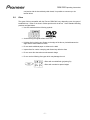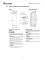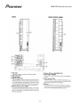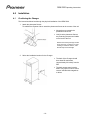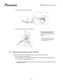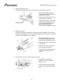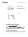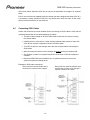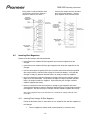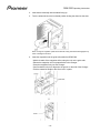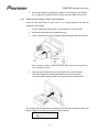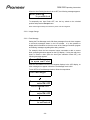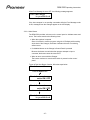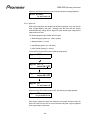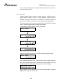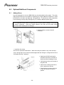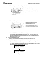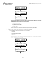
1
720-Disc DVD Library
DRM-7000
Operating Instructions
Manual Version 1.2
Released 26-February-2004
Pioneer Electronics (USA), Inc.
DRM-7000 Operating Instructions
(For US/Canadian Models)
CAUTION
•
•
Use of controls or adjustments or performance of procedures other than those specified
herein may result in hazardous radiation exposure.
The use of optical instruments with this product will increase eye hazard.
WARNING
This is a class A product. In a domestic environment this product may cause radio
interference in which the user may be required to take adequate measures.
This equipment has been tested and found to comply with the limits for a Class A digital
device, pursuant to Part 15 of the FCC Rules. These limits are designed to provide
reasonable protection against harmful interference when the equipment is operated in a
commercial environment. This equipment generates, uses and can radiate radio frequency
energy. If the equipment is not installed and used in accordance with the instruction
manual, it may cause harmful interference to radio communications. Operation of this
equipment is a residential area is likely to cause harmful interference in which case the user
will be required to correct the interference at his own expense.
INFORMATION TO USER
Alteration or modifications carried out without appropriate authorization may invalidate the
user’s right to operate the equipment.
CAUTION (for US model)
This product satisfies FCC regulations when shielded cables and connectors are used to
connect the unit to other equipment. To prevent electromagnetic interference with electric
appliances such as radios and televisions, use shielded cables and connectors for
connections.
CAUTION (for Canadian model)
This Class A digital apparatus meets all requirements of the Canadian Interference-Causing
Equipment Regulations.
The Generation of Acoustical Noise is Less Than 70 dB. (ISO 7779/DIN45635
Copyright © 1999-2004 Pioneer Electronic Corporation,
Pioneer Electronics (USA) Inc.
Printed in the United States of America
-i-
DRM-7000 Operating Instructions
Table of Contents
1.0 FEATURES OF THE DRM-7000 DISC CHANGER .......................................................................... 1
1.1
1.2
1.3
1.4
1.5
1.6
1.7
FLEXIBLE UNIT DESIGN .................................................................................................................. 1
TYPES OF DISC MAGAZINES ........................................................................................................... 1
EASE OF INSTALLATION .................................................................................................................. 1
SECURITY FEATURES..................................................................................................................... 2
LARGE LCD MESSAGE DISPLAY..................................................................................................... 2
EXPANDABILITY AND IMPROVEMENT ................................................................................................ 2
DISC CHANGING MECHANISM ......................................................................................................... 2
2.0 HANDLING PRECAUTIONS ............................................................................................................. 3
2.1
2.2
2.3
2.4
2.5
2.6
2.7
2.8
2.9
INSTALLATION SITE ........................................................................................................................ 3
UNPACKING AND HANDLING ........................................................................................................... 3
CONDENSATION............................................................................................................................. 3
CLEANING THE CHANGER ............................................................................................................... 3
MANAGING OFFLINE MEDIA ............................................................................................................ 4
DECIDING ON SYSTEM CONFIGURATION .......................................................................................... 4
PRODUCTS PROVIDED WITH THE DRM-7000 .................................................................................. 5
ADD-ON PRODUCTS ...................................................................................................................... 6
DISCS ........................................................................................................................................... 7
3.0 NAMES AND FUNCTIONS OF INDIVIDUAL PARTS....................................................................... 8
4.0 INSTALLATION ............................................................................................................................... 10
4.1
POSITIONING THE CHANGER ........................................................................................................ 10
4.2
BEFORE USING THE CHANGER FOR THE FIRST TIME ...................................................................... 11
4.3
CHANGING THE SCSI ID ON A DRM-7000 ................................................................................... 13
4.4
READING SCSI DRIVE IDS FROM THE DRM-7000 ........................................................................ 13
4.5
CONNECTING SCSI CABLES ........................................................................................................ 14
4.6
INSERTING DISC MAGAZINES ........................................................................................................ 15
4.6.1
Inserting Discs Using a 50-Disc Magazine ........................................................................ 15
4.6.2
Inserting Discs Using a 20-Disc Hyper-Magazine ............................................................. 17
4.7
MAGAZINE SLOT ASSIGNMENTS ................................................................................................... 18
4.8
CLOSING CHANGER ACCESS DOORS ............................................................................................ 18
5.0 OPERATION .................................................................................................................................... 20
5.1
USER MODE ................................................................................................................................ 20
5.2
SYSTEM ADMINISTRATOR MODE ................................................................................................... 20
5.2.1
Inquiry Submode................................................................................................................ 22
5.2.2
Config Submode ................................................................................................................ 22
5.2.3
Option Submode ................................................................................................................ 24
5.2.3.1
5.2.3.2
5.2.3.3
5.2.3.4
5.2.3.5
5.2.3.6
5.2.3.7
5.2.4
5.2.4.1
5.2.4.2
5.2.4.3
5.2.5
5.2.5.1
Auto Probing ................................................................................................................................ 25
Image Change.............................................................................................................................. 26
Free Message .............................................................................................................................. 26
Alert Buzzer.................................................................................................................................. 27
Hyper I/E ...................................................................................................................................... 28
Auto Eject..................................................................................................................................... 29
Hot Start ....................................................................................................................................... 30
Info Submode..................................................................................................................... 31
Log Data....................................................................................................................................... 31
Contents....................................................................................................................................... 32
Run-Statistics ............................................................................................................................... 32
Mail Slot Submode............................................................................................................. 34
Swap ............................................................................................................................................ 34
- ii -
DRM-7000 Operating Instructions
5.2.5.2
5.2.5.3
5.2.6
5.2.7
5.2.8
Remove........................................................................................................................................ 35
Add............................................................................................................................................... 35
Hyper Submode ................................................................................................................. 36
Probe Submode ................................................................................................................. 37
Door Submode................................................................................................................... 38
6.0 OPTIONAL/ADDITIONAL COMPONENTS..................................................................................... 39
6.1
6.2
ADDING DRIVES........................................................................................................................... 39
EXCHANGING DRIVES .................................................................................................................. 43
7.0 TROUBLESHOOTING..................................................................................................................... 46
8.0 SPECIFICATIONS ........................................................................................................................... 48
- iii -
DRM-7000 Operating Instructions
1.0
Features of the DRM-7000 Disc Changer
1.1
Flexible Unit Design
The Pioneer DRM-7000 Disc Changer is designed so that a various components may be
installed together to meet a variety of needs.
The Pioneer DRM-7000 provides easily, accessed bays on both the front and the back of the
unit as well as a hyper-magazine bay on the front. The bays support drives and/or 50-disc
magazines and are fitted with access panels for the installation or removal of individual
components.
While the front bays are designed exclusively for 50-disc magazines (up to a maximum of
seven magazines), the rear bays allow for mixed components. The rear bays support up to
sixteen drives or a maximum of eight 50-dsic magazines. By installing two drives per rear bay,
the maximum storage is increased to 720 discs. Conversely, it is also possible to install only
370 discs (filling the front bay and the hyper-magazine bay) and sixteen drives to maximize the
performance of the DRM-7000.
An alternative is to leave the bays unfilled immediately after installation and to add new drives
and/or disc magazines as needed.
1.2
Types of Disc Magazines
Pioneer offers three different types of disc magazines to support a wide variety of applications.
• 20-Disc Hyper Magazine
A single 20-disc magazine (included at no cost with the purchase of a DRM-7000) may
be installed and removed without opening an access panel. The lock, located on the
exterior of the changer, is equipped with a memory system that records all user
operations.
• 50-Disc Magazine (Locking)
This magazine is designed to maximize security. The locking mechanism prevents
removing a disc from a magazine through commands to the Changer. The locking
magazine is perfect for managing office media.
• 50-Disc Magazine
Fitted with a knob which releases the locking mechanism, this magazine makes it
possible to exchange discs between different magazines with commands sent to the
Changer.
1.3
Ease of Installation
In order to connect the Changer to an existing computer system or to build a new computer
system, it is necessary for the HOST computer to be able to properly identify the Changer and
the drives. All cables between the Changer and the HOST must be connected prior to
selecting the settings. The Pioneer DRM-7000 was designed for easy drive and magazine
installations but also with a wide range of features to make it easier to specify HOST settings.
Once all cables have been connected and the settings specified, the HOST computer is able to
control the Changer.
-1-
DRM-7000 Operating Instructions
1.4
Security Features
To prevent erroneous or unauthorized use, operators must be able to enter the system
administration mode from the Control Panel. In order to enter this mode, unlock the
mechanism using the provided keys. This feature also guards against interference, conflicts
and clashes occurring between operations performed from the Control Panel and commands
issued by the HOST computer.
An alternative method is to issue a command from the HOST to disable the Control Panel. It is
possible to restrict the types of operations that may be performed away from the HOST
computer. If the HOST sends a particular series of commands, a person with the Changer’s
keys is still prevented from opening access panels, exchanging discs, or otherwise altering any
internal settings on the Changer.
The software (which controls the Changer and manages the upper-level database) carefully
monitors access privileges and disc locations within the Changer. As a further precaution, if the
software on the HOST computer (or a server in a network environment) is not controlling the
Changer when a disc’s status is changed, access to the Changer and the installed drives is
lost. Allowing discs to be removed or swapped freely also poses a security risk because of the
potential for lost or damaged media. Although discs may still be added, exchanged or removed
via the access panels or through the disc mail slots, Pioneer recommends that a System
Administrator handle these security-sensitive activities.
1.5
Large LCD Message Display
The Control Panel is fitted with a large 2-line, 16-character LCD that displays operation
instructions. It is possible to perform a wide variety of operations on the DRM-7000 using just
five keys.
1.6
Expandability and Improvement
Pioneer will be releasing a disc turning or flipping unit for double-sided DVD discs, a network
interface connection, a video decoder, a DVD-R drive and other optional components to be
announced later. The DRM-7000 is designed so that these new components are easily
installed and automatically recognized by the system.
1.7
Disc Changing Mechanism
The Pioneer DRM-7000 Changer uses the same disc changing mechanism as the DRM-1004
series. This mechanism has an excellent record of high access speeds and proven reliability.
-2-
DRM-7000 Operating Instructions
2.0
Handling Precautions
2.1
Installation Site
Select an installation site with a flat, solid surface. Check the area for the following conditions:
• Avoid exposure to direct sunlight, spotlights or too near to a heater
• Beware of high humidity locations or sites exposed to large amounts of dust
• Avoid close proximity to a bathroom or a kitchen
• Maintain a distance from any large electrical apparatus (refrigerator, air conditioner.
etc.)
• Stay away from uneven or unsteady surfaces (if a surface is not flat, first put down a
hard plate or a similar support surface)
• Allow access to all sides of the unit for service and maintenance
• Do not places objects directly on top of the Changer
2.2
Unpacking and Handling
When handling the unit, be aware of the following factors:
• Avoid scratching, staining or leaving fingerprints on the signal surface or the recording
surface of the discs
• Insert and process a single disc at a time when using a mail slot
• Issue the SCSI command, INITIALIZE ELEMENT STATUS, after unloading or loading
a magazine
• The Changer manages the physical discs but not the content on the discs
• Use Pioneer-recommended discs when working with a DVD Writer (please note that
data recorded on to these disc is not covered by the warranty)
• Avoid stacking units or placing heavy objects on top of the unit
• The Changer supports 12cm discs only (inserting 8cm or 5cm discs may cause disc
detection errors and damaged discs)
2.3
Condensation
Water may form in the Changer if the environmental temperatures fluctuate beyond the
suggested range. For example, increasing the room temperature abruptly may cause
condensation. If condensation forms within the Changer, leave the Changer for one hour in the
room or increase the room temperature gradually before attempting to use it.
2.4
Cleaning the Changer
To clean the panels and the cover, use a soft, dry cloth to wipe off dust and dirt. If the cabinet
is heavily soiled, wipe off the dirt using a soft cloth soaked in a mild detergent that has been
diluted several times. Then, wipe off the dampness with a fresh dry cloth. Avoid using
-3-
DRM-7000 Operating Instructions
benzine, thinner, insecticide or other strong chemicals as these may dissolve or discolor the
cabinet surface. Some commercially produced chemical polishing clothes may be acceptable
but read all instructions and warnings first.
2.5
Managing Offline Media
The DRM-7000 provides the following features to manage of offline media.
• Removable Disc Magazines
Disc magazines may be removed from the Changer without removing the discs inside
thus making it possible to make more effective us of the space within the Changer.
Remove and store the magazines containing infrequently used discs.
• Unique Disc Magazine IDs for the DRM-7000
All disc magazines are assigned unique ID codes. The Changer reads this code as the
magazine is inserted into a bay. Each disc is accessible as soon as the magazine is
inserted into a bay. As long as the discs within the magazine match the database
information for that magazine ID. If a magazine is inserted into another Changer, the
new Changer recognizes the magazine if both Changers share the same database.
• Easy Disc Magazine Tracking and Controlling
Once a magazine has been assigned an ID, removing or inserting new discs into that
magazine disrupts the correspondence to the database. To avoid this problem,
purchase the 50-disc magazines with the locking mechanism. The locking magazine
prevents discs from being removed from a magazine while it is outside of the Changer.
Also use hyper magazines which track and record removal and insertion of new discs.
• Storage of Changer IDs
When a disc magazine has been inserted into a Changer not controlled by the
database management software or into a Changer belonging to another system, it is
possible for discs within that magazine to be rewritten or to be replaced with other discs
within that Changer. Locking magazines do not prevent rewrites or disc exchanges
when inserted into the Changer.
To protect the data, disc magazines are designed to record the IDs of the Changers in
which the magazines are used. As long as the list of Changer IDs is maintained within
the database, it is possible for the database management software to check the
magazine ID and the Changer ID list to determine whether that magazine has to be
reinstalled.
However, although the DRM-7000 Changer supports offline media, the actual media
management may differ because of the selected database software and the Changer
control software. Establish a set of management controls to handle the offline media.
To use non-locking magazines, the management controls must be very strict as these
magazines are usually unsuited for offline media management.
2.6
Deciding on System Configuration
Before installing the DRM-7000, decide which components are appropriate for your needs. To
determine what additional equipment to purchase, first decide where drives will be installed
(refer to the configuration guide at the end of this manual).
The SCSI board and SCSI cables supplied with the DRM-7000 are designed for use in the
following system configuration:
-4-
DRM-7000 Operating Instructions
• Two drives installed on separate cables
• Both drives are connected to the internal daisy-chain board using the cables provided
(it is necessary to purchase another SCSI cable to connect the Changer to the HOST)
To install three or more drives or to use more than one SCSI bus (to increase data transfer
rates), it is necessary to purchase additional SCSI boards and cables.
The following factors are key in selecting the appropriate components for your system.
• Types and numbers of drives and the bays to be used
(installing nine or more drives requires installation of an additional power supply)
• Positions where SCSI boards will be installed
(the Changer is equipped with an internal daisy-chain board and a drive board)
• SCSI ID to be assigned to each drive
(a SCSI ID may not be assigned to two or more drives on the same bus)
• Cable layout between the various drives and the SCSI boards
(refer to the Installation chapter, Examples of SCSI Cable Connections)
• Which drives will be terminated
(which drive will be at the end of the SCSI chain thus has the termination switch turned
ON)
The DRM-7000 is shipped with a single power supply which provides enough power for up to
eight devices installed in the lower rear bays (bay 1 through bay 8). The maximum power
supplied to the eight bays is 5V/12A or 12V/8A with no more than 5V/4A or 12V/4A over any
single connector. Thus any device installed in these bays must be below that power level.
An additional power supply must be added in order to install up to eight devices in the upper
rear bays (bay 9 through bay 16). The maximum power consumption for the upper bays is
equal to that of the lower bays.
WARNING: Use Pioneer-approved add-on products only
2.7
Products Provided with the DRM-7000
The following components are included with the original shipment of the Pioneer DRM-7000
Changer.
• 20-Disc Hyper Magazine
A single 20-disc magazine (included at not cost with the purchase of a DRM-7000) may
be installed and removed without opening an access panel. The lock, located on the
exterior of the changer, is equipped with a memory system that records all user
operations
• SCSI Drive Cable (1)
cable compatible with the market standard
• Power Cord (1-US/Canada & 1/Japan)
excess power cord may be discarded
• Placement Fixtures (set)
Set includes 4 brackets
• Chassis Keys (2)
-5-
DRM-7000 Operating Instructions
• 20-Disc Hyper Magazine Dust Cover
• Operating Instructions
• Warranty Information
• Service Network Sheet
2.8
Add-On Products
The following components may be purchased separately for use with the Pioneer DRM-7000
Changer.
• 50-Disc Locking Magazine (DRM-AL751)
This magazine is designed to maximize security. The locking mechanism prevents
removing a disc from a magazine through commands to the Changer. Use the Mail
Slot to add or exchange discs in this magazine.
• 50-Disc Magazine (DRM-AF751)
Fitted with a knob which releases the locking mechanism, this magazine makes it
possible to exchange discs between different magazines with commands sent to the
Changer.
• 20-Disc Hyper Magazine (DRM-AH721)
A single 20-disc magazine may be installed and removed without opening an access
panel. The lock, located on the exterior of the changer, is equipped with a memory
system that records all user operations. Additional hyper magazines may be
purchased in order to build an offline-library in 20-disc units.
• DVD-R/RW Drive (DVD-R7322)
The internal DVD-R/RW and CD-R drive may be used to read or write DVD/CD discs.
• DVD-ROM Drive (DVD-D7563)
The internal DVR drive may be used to read DVD and CD discs.
• Disc Flip Unit (DRM-UF701)
The disc-turning unit is designed for use of double-sided DVD discs within the
Changer.
• Power Supply (DRM-PW701)
The add-on power supply works in conjunction with the upper bays (bay 9 through bay
16).
• Multi-Drive Connector (DRM-SN721)
The DRM-SN721 is an internal daisy-chain board with a cable to connect two internal
drives. The board may be used to connect two or four additional drives in a daisychain.
• Single-Drive Connector (DRM-SN711)
The DRM-SN711 is a board used to connect a drive directly to the HOST computer
system or when a series of drives are daisy-chained outside of the Changer.
• Cable for Two Drives (DRM-SC721)
The two-drive SCSI cable is used to create a two-drive SCSI chain. When used in
conjunction with the internal daisy-chain board, it is possible to connect up to four
internal drives.
• Cable for Four Drives (DRM-SC741)
The four-drive SCSI cable is used to create a four-drive SCSI chain. When used in
-6-
DRM-7000 Operating Instructions
conjunction with the internal daisy-chain board, it is possible to connect up to six
internal drives.
2.9
Discs
The types of discs compatible with the Pioneer DRM-7000 vary depending upon the types of
installed drives. Refer to the User’s Guides provide with the drives. Some standard handling
practices are listed below.
• Use CDs marked with the following symbols
• Avoid touching the signal surface of the disc
• Hold the disc by placing your fingers on the edge of the disc or pinched between the
edge and the center hold on the disc
• Do not attach additional paper or stickers to the label
• Inspect discs for cracks or warping and discard any defective discs
• Do not use a disc that carries an electrostatic charge
• Do not use the following disc types which may damage the unit:
< Discs with a molded flash (projecting fin)
< Discs with rounded or tapered edges
-7-
DRM-7000 Operating Instructions
3.0
Names and Functions of Individual Parts
-8-
DRM-7000 Operating Instructions
-9-
DRM-7000 Operating Instructions
4.0
Installation
4.1
Positioning the Changer
The instructions below lead through the physical installation of the DRM-7000.
1. Attach the placement fixtures
To stabilize the Changer further, attach the placement fixtures at the corners of the unit
• Always be sure to attach the
placement fixtures first
• Verify that the placement fixtures
are protecting the ports and cables
on the back of the unit
Please note that any damage caused
to the rear ports or cables as a result
of failing to install the fixtures, voids
the warranty for that damage.
2. Select the installation location for the Changer
• The back of the Changer should
be at least 50 centimeters
(approximately 20 inches) from the
wall
• The back access panel must be
able to fully open in order to add or
remove individual disc magazines
or drives
- 10 -
DRM-7000 Operating Instructions
3. Lock all four legs/wheels into place
4. Connect the power cord to the Changer
• Insert the power cord into the
rear of the changer before
inserting the plug into the wall
socket
Caution: Always be sure to use
only a power cord designed for
use in that country.
4.2
Before Using the Changer for the First Time
To prepare the Changer for standard operation, follow the steps listed below.
1. Turn ON the power to the Changer
When the power is first turned on, the front and rear access panels automatically open
• Leave both access panel doors open
• If the power must be turned off for any reason, wait at least 10 seconds before turning
the power back on
- 11 -
DRM-7000 Operating Instructions
2.
Loosen the shipping screws
With the front access panel open, loosen the two screws located in the base
• Screws are permanent to avoid
becoming lost but must be loosened
to operate the Changer
• Tighten these screws before moving
or transporting the Changer
• Closing the front and/or rear access
panels cause the Changer to return
to the initial default position thus
leave access panels open to
continue with the installation process
3.
Install the drive units
No tools are required to install a drive. While drives may be installed in any of the rear
bays (bay 1 through bay 8), the connector board shipped with the Changer is configured
for drives to be installed into bay 1 and bay 2.
• Specify the SCSI IDs and set the
termination switches on the back of
the drives before installing the units
• Verify that the drives are mounted on
the guide rails
• Listen for the clicking sound as the
drive is pushed into the bay
• Push the drive in until the lock lever
on the drive shifts to the locked
position
4.
Connect the power cord from the Changer to the drive.
• Verify that the wiring monitor
indicator on the rear of the drive
lights as orange
• Check that the termination indicator
is green if the Termination Switch is
ON
- 12 -
DRM-7000 Operating Instructions
5.
Connect the Changer Interface cable to the drive.
• Confirm that the interface cable is
connected to the correct bay
Caution: Connecting the interface cable to an
incorrect bay port results in damage to the discs.
• Install an add-on connector board if
necessary
4.3
Changing the SCSI ID on a DRM-7000
To alter the Changer’s SCSI ID, power the system OFF then press the SCSI ID switches
located on the back of the unit in the lower left area. Pressing the switches causes the ID to
change and the following message to appear on the LCD display.
(Inquiry)
ID = 6 ( 0 )
Revision *.***
In this example, the Changer’s SCSI ID changes from SCSI ID 6 to SCSI ID 0.
Powering the system back ON resets the SCSI bus to the host computer. The new SCSI ID for
the DRM-7000 is maintained until the SCSI ID switches on the back of the unit are altered.
4.4
Reading SCSI Drive IDs from the DRM-7000
If all drives have been assigned separate SCSI IDs, a buzzer sounds once. If the same SCSI
ID has been assigned to two or more drives, the buzzer sounds three times. Installing multiple
- 13 -
DRM-7000 Operating Instructions
SCSI buses allows duplicate SCSI IDs as long as the duplicates are assigned to separate
buses.
Even if none of the drives installed within the changer has been assigned the same SCSI ID, it
is necessary to assign a different SCSI ID to any drives which share the same ID with other
devices such as hard drives on the same bus.
4.5
Connecting SCSI Cables
Confirm that all drives have been installed, before connecting the SCSI cables. Check that all
conditions listed below are met below attaching the cables.
• The total combined length of all SCSI cables must be less then six meters, including
the internal cables.
• Installing seven or more drives, or when creating separate daisy chains for fewer than
seven drives, requires a separate multi-drive connector panel.
• Turn OFF the power to the Changer and to the host computer before connecting the
SCSI cables.
• After connecting the cables, turn the Changer ON before turning the computer ON.
• The Changer is unable to recognize faulty SCSI connections or SCSI ID assignment
mistakes.
• Reboot the DRM-7000 after installation new or replacement drives to ensure the
system recognizes all existing drives.
Examples of SCSI cable connections:
Daisy-chain two internal readers and a
recorder then connect to the Changer
- 14 -
Daisy-chain four internal readerse and a
recorder then connect to the Changer –
requires a cable for two drives
DRM-7000 Operating Instructions
Daisy-chain six internal readers and a
recorder then connect the Changer –
requires a cable for four drives
4.6
Connect two readers and two recorders
then connect the Changer – requires
three separate SCSI controller cards
Inserting Disc Magazines
Please review the insertion methods listed below.
• Insert discs into a standard 50-disc magazine then insert the magazine into the
Changer.
• Insert discs into a standard 20-disc hyper-magazine then insert the magazine into the
Changer.
• Use the control panel to specify which slot will receive a disc then select the specified
disc number from the mail slot (refer to page 32 for mail slot details). Verify that the
Changer is ready for operation and that there is an empty slot within a magazine.
• Issue a command from the host computer to accept a disc from the mail slot (refer to
page 32 for mail slot details). Verify that the Changer is ready for operation and that
there is an empty slot within a magazine. Also check that your Changer controller
software supports this activity.
• Issue a command from the host computer to accept a hyper-magazine with discs.
Verify that the Changer is ready for operation and that the bay is empty before inserting
the magazine. Also check that your Changer controller software supports this activity.
Note: Hyper-magazines may not be removed from or added to the Changer while the unit is
turned OFF.
4.6.1
Inserting Discs Using a 50-Disc Magazine
Follow the directions below to insert discs in to a magazine then add the magazine to
the Changer.
1. Turn the magazine’s release knob (vertical position) to unlock the slots.
- 15 -
DRM-7000 Operating Instructions
2. Insert discs horizontally with the labels facing up.
3. Turn the release knob to the horizontal position locking the discs into the slots.
Note: Turning the magazine upside-down with the locking mechanism disengaged may
result in damage to the discs.
4. Insert the magazine onto the guide rails within the DRM-7000.
* Hold the handle of the magazine while resting the unit on the guide rails.
* Elevate the magazine until it is perpendicular to the Changer.
* Press the magazine firmly into the Changer.
* Confirm that the lock pin is aligned to the groove on the side of the Changer.
* Fold the magazine handle to the left to lock it in place.
- 16 -
DRM-7000 Operating Instructions
5. Remove the magazine by flipping the handle out and pulling the unit towards
you. Support the magazine so that it remains level as it slides off of the rails.
4.6.2
Inserting Discs Using a 20-Disc Hyper-Magazine
Follow the directions below to insert discs in to a hyper-magazine then add the
magazine to the Changer.
1. Turn the magazine’s release knob (vertical position) to unlock the slots.
2. Insert discs horizontally with the labels facing up.
3. Turn the release knob to the horizontal position locking the discs into the slots.
Note: Turning the magazine upside-down with the locking mechanism disengaged may
result in damage to the discs.
4. Insert the hyper-magazine into the top bay above the front access door.
* Once the magazine is inserted approximately half way into this bay,
the changer automatically pulls the unit forward until it is locked in place.
The Changer automatically reads the magazine ID and lists the information on the LCD
display a few seconds after a successful magazine insertion.
M1
Locked – type
ID = * * * * * * * * * * * *
- 17 -
DRM-7000 Operating Instructions
A similar message appears when a magazine is removed from the Changer.
M1
Locked – type
out
If these messages appear repeatedly in rapid succession, the magazine is improperly
inserted into the bay. Remove the magazine and remount the unit into the appropriate
Changer bay.
4.7
Magazine Slot Assignments
Each possible slot in the Changer bays is assigned a unique serial number. These numbers
remain the same if the bay holds a magazine or a drive. Changing magazines does not change
the slot serial number. The following chart identifies each bay and the corresponding slot serial
numbers assigned to that bay.
Disc Storage Location
Slot Number
Disc Storage Location
Slot Number
(Disc Number)
(Disc Number)
Slot 20
# 770
Hyp-20
Slot 50
# 750
M15 – 50
Hyper Magazine
Magazine Bay 15
to
to
to
to
to
to
Hyper
M15
Slot 1
# 751
Hyp-01
Slot 1
# 701
M15 – 01
Slot 50
# 350
M7 – 50
Slot 50
# 700
M14 – 50
Magazine Bay 7
Magazine Bay 14
to
to
to
to
to
to
M7
M14
Slot 1
# 301
M7 – 01
Slot 1
# 651
M14 – 01
Slot 50
# 300
M6 – 50
Slot 50
# 650
M13 – 50
Magazine Bay 6
Magazine Bay 13
to
to
to
to
to
to
M6
M13
Slot 1
# 251
M6 – 01
Slot 1
# 601
M13 – 01
Slot 50
# 250
M5 – 50
Slot 50
# 600
M12 – 50
Magazine Bay 5
Magazine Bay 12
to
to
to
to
to
to
M5
M12
Slot 1
# 201
M5 – 01
Slot 1
# 551
M12 – 01
Slot 50
# 200
M4 – 50
Slot 50
# 550
M11 – 50
Magazine Bay 4
Magazine Bay 11
to
to
to
to
to
to
M4
M11
Slot 1
# 151
M4 – 01
Slot 1
# 501
M11 – 01
Slot 50
# 150
M3 – 50
Slot 50
# 500
M10 – 50
Magazine Bay 3
Magazine Bay 10
to
to
to
to
to
to
M3
M10
Slot 1
# 101
M3 – 01
Slot 1
# 451
M10 – 01
Slot 50
# 100
M2 – 50
Slot 50
# 450
M9 – 50
Magazine Bay 2
Magazine Bay 9
to
to
to
to
to
to
M2
M9
Slot 1
# 051
M2 – 01
Slot 1
# 401
M9 – 01
Slot 50
# 050
M1 – 50
Slot 50
# 400
M8 – 50
Magazine Bay 1
Magazine Bay 8
to
to
to
to
to
to
M1
M8
Slot 1
# 001
M1 – 01
Slot 1
# 351
M8 – 01
Note: Although slot numbers range up to 770, it may not be possible to insert a total of 770 discs
simultaneously.
4.8
Closing Changer Access Doors
Before closing the access doors, verify that all components are mounted correctly and that all
cables are firmly in place. Closing the access doors begins the initialization of the DRM-7000.
- 18 -
DRM-7000 Operating Instructions
Once the initialization is complete, the following message appears in the LCD display:
Robotics
Drive1
ready
no disc
The first line of the message refers to the status of the disc changer mechanism. The second
line indicates the disc number and registers any loaded discs. Drive numbers are assigned in
sequence from the lowest to the highest number.
Note: If the number of drives registered exceeds the maximum number of drives allowed for
installation, open the rear access door and check the drive power cables and the interface
connections. See the section entitled, System Administration mode: Access Panel Submodes, for
additional information.
- 19 -
DRM-7000 Operating Instructions
5.0
Operation
The DRM-7000 supports two modes, User and System Administrator. Separating the operations
into two modes prevents interference, conflicts, or clashes from occurring between commands
issued from the host computer and commands entered at the Changer’s Control Panel.
5.1
User Mode
Upon installation, the Changer enters the User Mode. This mode allows the Changer’s
controller software or database management software on the host computer to run the unit.
When operating in the User Mode, the Changer flashes a series of messages shown below.
Robotics
Drive1
ready
no disc
Robotics
Drive2
ready
no disc
Robotics
Drive1
busy
no disc
Robotics
Drive2
ready
has #205
When in the User Mode, the Changer responds to commands issued from the host computer.
5.2
System Administrator Mode
Issuing commands from the Changer’s Control Panel is restricted to System Administrators
with the panel keys. To switch the System Administrator Mode, follow the steps below.
1.
Insert the key into the key switch located on the control panel.
2.
Rotate the key 90 degrees to the unlocked position.
3.
Press the Function button to enter the System Administrator Mode.
- 20 -
DRM-7000 Operating Instructions
When operating in the System Administrator Mode, the Changer shows the following message
in the LCD display.
(Inquiry)
ID = 5
Revision 1.00
The System Administrator Mode is divided into four Information submodes and four Operation
submodes.
Information Submodes
• Inquiry Submode
• Config Submode
• Option Submode
• Info Submode
Operation Submodes
• Mail slot Submode
• Hyper Submode
• Probe Submode
• Door Submode
The System Administrator mode setting screens are displayed in the sequence shown
below.
- 21 -
DRM-7000 Operating Instructions
Information submodes enable a System Administrator to check a Changer’s current settings or
read the stored data. The System Administrator may also view a variety of Changer
information without interfering with the control of the Changer from the host computer.
Operation submodes allow movement to the disc changing or magazine ejection mechanisms,
disc replacement, and slot availability checks. Operation Submodes cause the Changer to
ignore commands issued from the host computer.
5.2.1
Inquiry Submode
The Inquiry Submode displays general information about the DRM-7000 system.
Issuing a SCSI INQUIRY command from the host computer provides the same
information about the Changer. The data includes SCSI IDs and the unit’s serial
number.
The first screen shows the Changer’s SCSI ID number.
(Inquiry)
ID = 5
Revision *.***
Pressing the Enter button causes the unit’s model name and serial number to appear
on the LCD display.
DRM-7000
Serial = ********
Pressing the Escape button causes the display to return to the previous message.
To alter the Changer’s SCSI ID, refer to the earlier section in this manual entitled,
Changing the SCSI ID for a DRM-7000.
5.2.2
Config Submode
The Config Submode provides component installation checks. The components include
all magazines and devices in both front and rear bays.
(Config)
Setup browser
Pressing the Enter button reveals the SELECT BAY screen. Use the up and down
arrows to select the appropriate bay.
Magazine – bay or
Rear (drive) – bay?
Example of Rear Bay selection:
Press the Enter button again to reveal the component currently inserted in the rear
drive bay #1.
Bay # 1
=
Drive 1
DVDROM DVD-D7361
- 22 -
DRM-7000 Operating Instructions
To change the selected bay, use the up and down arrow buttons.
Example:
arrow button
Bay # 5 & # 6
flip unit
arrow button
Bay # 9
no component
arrow button
Bay # 15 & # 16
ID = ************
If the bay holds a drive, press Enter to display the SCSI ID, the termination switch
setting and the device ID of the drive.
scsi ID = 1
TermOFF
dev – ID = ********
If a disc is inserted in the drive, press Enter to display the disc number.
Disc
in
Drive 1
is # ***
(M** – **)
Note: Pressing the Escape button causes the screen to return to the previous view. Each time
this button is pressed, the display backs up by one screen.
To view drive information, press the Escape button to return to BAY SELECTION and
choose the appropriate rear bay.
Example of Hyper Magazine Bay selection:
Press the Enter button to reveal the hyper magazine ID.
Hyper magazine
ID = ************
If the hyper magazine bay is empty, the following message appears on the display:
Hyper magazine
removed
Hyper magazines include a memory system that keeps a record of each time the
release locking mechanism unlocks the magazine. Pressing the Enter button while a
hyper magazine is installed causes these records to appear on the LCD display.
- 23 -
DRM-7000 Operating Instructions
If the locking record log is empty, the following message appears:
Locked – state
When there are records in the memory, the following message appears:
Uncertain – state
Example of Magazine Bay selection:
Press the up arrow button while the hyper magazine information displays to show
Magazine #1.
M1 (front – bottom)
ID = ************
Each time the up arrow button is pushed, the next sequential magazine appears on the
LCD display.
arrow button
M2
ID = ************
If the magazine bay is empty, the following message appears on the LCD display.
M7 (rear – bottom)
removed
With rear bays, there may be times when a bay is occupied with a drive instead of a
magazine. The following message appears when this is the situation.
M8 (rear – bottom)
not available
When a magazine is shown on the display, press the Enter button to reveal the type of
magazine installed in that bay.
Normal – type
Pressing the up arrow button while magazine bay #15 is selected, returns the display to
the hyper magazine information.
5.2.3
Option Submode
Many controller and data management software packages provide additional tools and
operations to the System Administrator. To work with these features, select an
operation from the Option Submode commands.
(Option)
User’s choice
- 24 -
DRM-7000 Operating Instructions
The optional operations are as follows when scanning using the right arrow button:
• Auto Probing – default set to OFF at time of shipment
• Inquiry Change – default set to OFF at time of shipment
• Free Message – default set to Off at time of shipment
• Alert Buzzer – default set to ON at time of shipment
• Hyper I/E – default set to ON at time of shipment
• Auto Eject – default set to ON at time of shipment
• Hot Start – default set to OFF at time of shipment
5.2.3.1 Auto Probing
When standard 50-disc and hyper magazines have discs added while outside
of the DRM-7000, the system requires a slot check before accessing the new
discs. An Auto Probe command checks all magazine slots in sequence to
determine whether each slot is empty or full. The Controller software usually
performs this check. However, if the software fails to support this activity or the
Changer is disconnected from a host computer, use the Auto Probing function.
Commands from the host computer are ignored during an Auto Probe issued
through the controller program.
Even after switching Auto Probing from OFF to ON, the feature is unavailable
until an access door is opened then closed or until the unit is reset.
Auto probing?
Press the Enter button
Auto probing is
set to ON / OFF
Press the left arrow button
Auto probing is
set to ON / OFF
Press the Enter button
Auto probing
is activated
- 25 -
DRM-7000 Operating Instructions
When the Auto Probing function is set to OFF, the following message appears:
Auto probing
is prohibited
To temporarily turn Auto Probe OFF, turn the key switch to the unlocked
position and press the Escape button.
Note: It takes approximately two minutes to probe a 50-disc magazine.
5.2.3.2 Image Change
5.2.3.3 Free Message
Setting the Free Message mode ON allows messages from the host computer
to over-write messages shown in the LCD window. It is also possible to
display other information such as the name of the Changer Controller program
and warning messages regarding discs being rewritten.
For example, when the host computer issues commands to add or remove
discs, prompting directions appear on the LCD display. If using the mail slot to
insert or remove a disc (with the Auto Eject submode turned OFF), the
following message appears:
Press ENT-key
to open mail slot
While this information from the host computer displays in the LCD display, no
other messages can appear unless the Free Message mode is ON.
To turn OFF the Free Message function, follow the steps below.
Free message?
Press the Enter button
Free message is
set to ON / OFF
Press the left arrow button
Free message is
set to ON / OFF
Press the Enter button
Free message
is activated
- 26 -
DRM-7000 Operating Instructions
When Free Message is set to OFF, the following message appears:
Free message
is prohibited
If the host computer is not sending commands while the Free Message mode
is ON, messages from the Changer appear on the LCD display.
5.2.3.4 Alert Buzzer
The DRM-7000 provides a buzzer on the control panel to indicate status and
errors. The buzzer sounds at the following times:
• When the rear door is opened
Since it is difficult to monitor progress using the LCD display while working
at the back of the Changer, the buzzer indicates that work is continuing
without errors.
• If a disabled button on the Changer’s Control Panel is pressed
Because the buzzer sounds when the operator attempts to input a
command, the buzzer cannot be turned OFF.
• When an error occurs with the Changer
The buzzer continues to sound until a button is pressed on the control
panel.
To turn off the Alert Buzzer function, follow the steps below.
Alert buzzer?
Press the Enter button
Alert buzzer is
set to ON / OFF
Press the right arrow button
Alert buzzer is
set to ON / OFF
Press the Enter button
Alert buzzer
is prohibited
- 27 -
DRM-7000 Operating Instructions
When the Alert Buzzer function is set to ON, the following message appears:
Alert buzzer
Is activated
5.2.3.5 Hyper I/E
While hyper magazines are designed as 20-disc magazines, they may also be
used as high-capacity mail slots. Although slots and mail slots are usually
defined differently, turning ON the Hyper I/E mode allows hyper magazines to
respond like mail slots.
The SCSI subsystems are divided into four types:
• Media Changing System (i.e. robotic system)
• Storage System (i.e. slots)
• Import/Export system (i.e. mail slots)
• Data Transfer System (i.e. drives)
To turn OFF the Hyper I/E function, follow the steps below.
Hyper I/E?
Press the Enter button
Hyper I/E is
set to ON / OFF
Press the left arrow button
Hyper I/E is
set to ON / OFF
Press the Enter button
Hyper I/E
is activated
When the Hyper I/E function is set to OFF, the following message appears:
Hyper I/E
is prohibited
Since hyper magazines retain their attributes as storage elements while the
Hyper I/E mode is set to ON, the control software may treat a hyper magazine
as an import/export component.
- 28 -
DRM-7000 Operating Instructions
If the controller software does not support multiple import/export elements, set
the Hyper I/E mode to OFF.
5.2.3.6 Auto Eject
Changers installed within a network are often located in a different room or
possibly another building. If a disc or a hyper magazine is ejected while an
attendant is away from the Changer, it is possible for unauthorized personnel
to remove the media from the mail slot or the magazine from the hyper bay.
To maintain security, the Auto Eject command can be turned OFF thus sealing
a disc or a hyper magazine within the DRM-7000 Chassis.
To turn off the Auto Eject function, follow the steps below.
Auto eject?
Press the Enter button
Auto eject is
set to ON / OFF
Press the right arrow button
Auto eject is
set to ON / OFF
Press the Enter button
Auto eject
is prohibited
When the Auto Eject function is set to ON, the following message appears:
Auto eject
is activated
If the Auto Eject command is set to OFF when the host computer issues an
Eject Disc command, the media is moved to the mail slot tray but the tray
remains closed. The following message appears on the LCD display.
Press ENT-key
to open mail slot
On the Changer, turn the Administrator key to the unlocked position. Press the
Enter button to open the mail slot tray.
- 29 -
DRM-7000 Operating Instructions
Similarly, a command from the host computer to eject a hyper magazine while
Auto Eject is set to OFF results in the following message.
Press ENT-key
to eject hyper
Use the Administrator key to Unlock the Changer and remove the hyper
magazine.
5.2.3.7 Hot Start
If discs are left in the drives when the power to the Changer is turned OFF then
ON, the discs are automatically returned to their original slots. This operation
fails to activate after a SCSI reset.
Before selecting the Hot Start function, choose the disc or discs that must
remain in the drives. Activate the Hot Start command to retain frequently used
discs in the drives upon powering ON the DRM-7000.
Hot start?
Press the Enter button
Hot start is
set to ON / OFF
Press the left arrow button
Hot start is
set to ON / OFF
Press the Enter button
Hot start
is activated
When the Hot Start function is set to OFF, the following message appears:
Hot start
is prohibited
Note: Unless the controller software allows discs to remain in the drives when powering
up the system, a Hot Start is unavailable.
- 30 -
DRM-7000 Operating Instructions
5.2.4
Info Submode
The DRM-7000 stores data needed for daily maintenance in non-volitile memory. The
Info Submode provides access to this information.
(Info)
Data browser
Press the Enter button while this message is on the LCD display in order to select the
type of data to retrieve. The following message appears:
Log, Contents or
Run-statistics?
Move the cursor to the type of data required then press the Enter button.
5.2.4.1 Log Data
When requesting log data, it is possible to display an error log or an import log.
Error – log or
Import – log?
Use the arrow buttons to high-light either Error Log or Import Log then press
Enter to select the log.
ERROR LOG
An error log retains the code with a brief description of the problem. The
Changer stores up to a maximum of 32 errors in a log with the most recent
error displayed first. To view the error description, place the cursor over an
error code then press the Enter button.
See below for an example of an error.
1:E89
3:EE9
2:E83
4:E99
Press the Enter button
1:Timeover on
Elevation
IMPORT LOG
An import log provides a sequential list of all newly filled slots when adding or
exchanging discs through the mail slot.
Discs within a magazine are displayed as a single unit.
Imported are
#098 , #121 , #122 ,
Press the Up arrow button
- 31 -
DRM-7000 Operating Instructions
#123 , #221 , #258 ,
M15 (#701 - #750),
Press the Up arrow button
Hyper (#751 - #770) ,
end of list
5.2.4.2 Contents
Request a Content log to review the number of filled and vacant slots within the
combined magazines.
Full slots
Empty slots
: 588
: 12
Press Up or Down arrow button
Uncertain
Total slots
: 70
: 670
The label, Uncertain, indicates that the Changer is unable to determine if a disc
is in a slot.
5.2.4.3 Run-Statistics
The Run-Statistics command displays the length of time or the number or times
an operation has been performed.
Work-time sum or
Number of moves?
Move the cursor to either Work Time Sum or Number of Moves and press the
Enter button to see the data log.
Work-Time Sum
Select PowerON time to show the total length of time that power has been ON
for the DRM-7000.
PowerOn-time or
Drive work-time?
Press the Enter button
Total PowerOn is
******hours**min
- 32 -
DRM-7000 Operating Instructions
Select Drive Work Time to reveal the total time each drive has been in
opration.
PowerOn-time or
Drive work-time?
Press the Enter button
Drive 1
works
******hours**min
Press the Up arrow button
Drive 2
works
******hours**min
Press the Up arrow button
Drive 3
works
******hours**min
The total length of time is maintained for each unique drive device ID. Thus, if
a device is moved to another bay, the correct data appears in the LCD display.
Number of Moves
Use the Up and Down arrow buttons to scroll between the following four
operations.
• Elevation Done: indicates the number of times the elevation mechanism
has raised/lowered
This log is primarily a service and maintenance reference tool.
• Load/Unload Drive: indicates the number of times the loading mechanism
has loaded or unloaded a disc (loading and unloading a specific disc in a
specific slot counts as two operations)
This log is primarily a service and maintenance reference tool.
• Mail Slot Driven: indicates the number of times the mail slot is used to
insert or remove a disc
An open-and-close operation counts as a single use.
• Hyper Driven: indicates the number of times the hyper magazine is
inserted or ejected
An insert-and-eject operation counts as a single use.
- 33 -
DRM-7000 Operating Instructions
Elevation done
****** times
Press Down or Up arrow button
Load/Unload done
****** times
Press Down or Up arrow button
Mail slot driven
****** times
Press Down or Up arrow button
Hyper driven
****** times
5.2.5
Mail Slot Submode
Use the Mail slot submode to control disc movement (exchange, eject or add) through
the Changer’s control panel.
Although the host computer usually controls disc insertion or removal, a system
administrator may access any disc using this submode command. However, the
administrator must record which slots are changed and update the database if
necessary. Access the Import Log submode to view the changes.
(Mail slot)
Import & Export
Press the Enter button to call up the Swap, Remove or Add some discs menu. If the
action needs to be other then the default setting of Swap, arrow to the appropriate
command. Press the Enter button to make the selection.
Swap, Remove or
Add some discs?
5.2.5.1 Swap
After selecting the Swap option, use the up and down arrow buttons to specify
the slot number for swapping discs. Press the Enter button to select the slot.
SlotNo.?
#***
M** - **
This command ignores slots that are empty but includes slots which may hold
discs (unknown). Each time the up or down arrow button is pushed, the slots
appear in sequence.
Removing #***
as the old disc
- 34 -
DRM-7000 Operating Instructions
If there is a disc in the specified slot, the disc is carried to the mail slot. The
mail slot tray opens and the following message appears on the LCD display.
Replace disc
& press ENT-key
If the specified slot is empty, the mail slot tray opens and the following
message appears on the LCD display.
Place a new disc
& press ENT-key
Place a disc on the mail slot tray and press the Enter button. The following
message appears on the LCD display:
The new disc is
moving to #***
When the slot holds the replacement disc, the LCD display changes to the
initial Swap message showing the next swappable slot.
To exit the mode, press the Enter button again.
5.2.5.2 Remove
After selecting the Remove option, use the up and down arrow buttons to
specify the slot number. Press the Enter button to select the slot.
DiscNo.?
#***
M** - **
A slot must contain a disc in order to use this command. It the slot is empty or
is unknown to hold a disc when the Enter button is pressed, the message on
the LCD display remains unchanged.
The disc in the specified slot is carried to the mail slot. The mail slot tray
opens and the following message appears on the LCD display.
Remove the disc
& press ENT-key
Remove the disc from the open tray and press the Enter button again to close
the tray. After the disc is removed, the LCD display changes to the initial
Remove message listing the next appropriate slot.
To exit the mode, press the Enter button again.
5.2.5.3 Add
After selecting the Add option, use the up and down arrow buttons to specify
the slot number. Press the Enter button to select the slot.
SlotNo.?
#***
M** - **
- 35 -
DRM-7000 Operating Instructions
The slot must be empty in order to use this command. It the slot contains a
disc or is unknown to hold a disc when the Enter button is pressed, the
message on the LCD display remains unchanged.
If the specified slot is empty, the mail slot tray opens and the following
message appears on the LCD display.
Place a new disc
& press ENT-key
Place a disc on the mail slot tray and press the Enter button. The following
message appears on the LCD display:
The new disc is
moving to #***
When the slot contains the new disc, the LCD display changes to the initial Add
message showing the next available slot.
To exit the mode, press the Enter button again.
Note: If you are unable to insert a new disc using the Add mode, add the disc in the
Swap mode instead.
5.2.6
Hyper Submode
Use the Hyper submode to eject hyper magazines through the Changer’s control panel.
The Enter button acts as an eject button when the DRM-7000 is in this mode.
(Hyper)
Eject & Inject
Pressing the Enter button causes the Changer to check the drives for discs
registered to a hyper magazine. If any hyper magazine discs are in a drive, the
following message appears on the LCD display.
Host must return
all hyper’s disc
The host computer has the authority to return discs to the magazine slots. The
system must be in User mode when the host computer issues the command.
Once any/all discs are returned to the hyper magazine, the following message
appears on the LCD display.
Press ENT-key
to eject
Pressing the Enter button causes the system to eject the hyper magazine.
Hyper – magazine
is unloading
Hyper – magazine
Is ejected
- 36 -
DRM-7000 Operating Instructions
To exit this mode without inserting a hyper magazine, press the Escape key
three times to return to the User mode.
To replace a hyper magazine, eject the current hyper magazine according to
the preceding instructions then partially insert the new hyper magazine. The
changer automatically senses and draws in the magazine. Never force a
magazine into a bay. The following message appears on the LCD display
when a hyper magazine is inserted properly.
Hyper – magazine
is loading
When a hyper magazine is loaded, a unique ID and a log of the magazine’s
locking mechanism usage appears on the LCD display.
If the usage log is empty, the following message appears:
Locked – state
ID # ************
If the usage log includes data, the following message appears:
Uncertain – state
ID # ************
The magazine is automatically ejected if the Changer is unable to read the ID.
Reinsert the magazine to attempt to read the ID again.
5.2.7
Probe Submode
The Probe submode checks for discs within slots when a magazine is loaded while
outside of the Changer. Usually the controller software performs this task but if the
changer is not connected to a host computer, this submode issues a check for discs
within a magazine’s slots. Use the Probe submode if the controller program fails to
offer this option.
(Probe)
Slot initialization
Press the Enter button to scroll in sequence through the bays containing magazines.
Initialize
slots of M1?
Press the Up Arrow or Down Arrow button to scroll to a magazine then press the
Enter button to select the magazine. The DRM-7000 automatically scans the
magazine slots in sequence for discs.
M1 – 01
. . . . . .
- 37 -
DRM-7000 Operating Instructions
M1 – 01
M1 – 02
. . . . . .
full
M1 – 02
M1 – 03
. . . . . .
M1 – 50
Continue?
full
Yes / No
empty
When all slots within a magazine are checked for discs, you have the option to
continue checking magazines for discs. Press the Enter button to confirm your
selection.
Once a magazine is probed and it remains within the DRM-7000, the disc and slot
information is logged. There is no need to perform the check again as long as the
magazine is in the changer or is locked while outside of the changer.
5.2.8
Door Submode
The Door submode opens the access panels or doors to swap 50-disc magazines, to
swap drives, or to add discs. To open an access panel, all discs must be returned to
the appropriate magazine slots or to the mail slots. The submode appears as follows.
(Door)
Open & Rebuild
Press the Enter button to confirm that all drives are empty. If any discs remain in a
drive, the following message appears on the LCD display.
Host must return
every disc first
Press the Escape button to return to the User mode and issue the Return All Discs
command from the host computer before issuing the Door submode again.
After all drives are confirmed as empty, press the Up Arrow or Down Arrow button to
select the access door to open.
Front, Rear
or Both?
Press the Enter button to open the selected panel(s).
Front-door
Rear-door
:Open
:Close
The system automatically returns to User mode when an access door is opened. To
use a different submode, press the Function button to re-enter the System
Administrator mode.
- 38 -
DRM-7000 Operating Instructions
6.0
Optional/Additional Components
6.1
Adding Drives
Any drive designed for use in the DRM-7000 may be easily added to this system. The power
supply shipped with the unit is capable of supporting up to eight additional components. Install
the devices in to the lower rear bays (bay 1 through bay 8). To add drives or other components
to the remaining rear bays (bays 9 thought bay 16), install an additional power supply.
Touch a separate metallic surface to discharge static electricity before handling a power supply
or another component. Avoid any contact between your body and the power supply
connections when installing into the Changer.
• Install an add-on connector board if
necessary
1. Install the drive unit(s)
No tools are required to install a drive. While drives may be installed in any of the rear bays
(bay 1 through bay 8), the connector board shipped with the Changer is configured for drives to
be installed into bay 1 and bay 2.
• Specify the SCSI IDs and set the
termination switches on the back of
the drives before installing the units
• Verify that the drives are mounted on
the guide rails
• Listen for the clicking sound as the
drive is pushed into the bay
• Push the drive in until the lock lever
on the drive shifts to the locked
position
- 39 -
DRM-7000 Operating Instructions
2. Connect the power cord from the Changer to the drive.
• Verify that the wiring monitor indicator on
the rear of the drive lights as orange
• Check that the termination indicator is
green if the Termination Switch is ON
3. Connect the Changer Interface cable to the drive.
• Confirm that the interface cable is
connected to the correct bay
Caution: Connecting the interface cable to an
incorrect bay port results in damage to the discs.
4. Allow the DRM-7000 to read the SCSI IDs on the drive(s).
If all drives have individual SCSI IDs, a buzzer sounds once. If there are duplicate IDs
assigned to separate drives then the buzzer sounds three times. Each device on a SCSI
bus requires a unique SCSI ID.
5.
Connect the SCSI interface cable.
Any drives disconnected during an earlier step, should be reconnected at this time.
6.
Enter the Config submode from the System Administrator mode.
Verify that the DRM-7000 recognizes all drives before proceeding. Check the wiring monitor
indicator on the back of each drive if necessary.
For example: the following messages appear when three DVD-ROM drives and a CD-ROM
drive are added to the rear bays beginning from bay #1.
Bay # 1 =
Drive1
DVDROM DVD-D7563
Press the Up arrow button
Bay # 2 =
Drive2
DVDROM DVD-D7563
Press the Up arrow button
- 40 -
DRM-7000 Operating Instructions
Bay # 3 =
Drive3
DVDROM DVD-D7563
Press the Up arrow button
Bay # 4 =
Drive4
DVD-R
DVD-R7322
Press the Up arrow button
Bay # 5 & # 6
no component
If a wiring monitor indicator on the back of the drive remains off, the cables may need to be
reseated. Disconnect the cables in the following order:
1 – SCSI Interface cable
2 – Changer Interface cable
3 – Power cable
Reverse the order to re-connect the drive thus beginning with the power cable.
7.
Press the Enter button to move up one level to reveal all drive settings.
The following drive identification appears on the LCD display:
• SCSI ID
• Termination switch setting
• Device ID
For example, if four drives are daisy-chained and the last unit in the chain has termination
ON, the messages appear as follows:
Bay # 1 =
Drive1
DVDROM DVD-D7563
Press the Enter button
scsi ID = 1
TermOFF
dev – ID = 00071033
Press Enter then the Up arrow
Bay # 2 =
Drive2
DVDROM DVD-D7563
Press the Enter button
- 41 -
DRM-7000 Operating Instructions
scsi ID = 2
TermOFF
dev – ID = 00150360
Press Enter then the Up arrow
Bay # 3 =
Drive3
DVDROM DVD-D7563
Press the Enter button
scsi ID = 3
TermOFF
dev – ID = 00000408
Press Enter then the Up arrow
Bay # 4 =
Drive4
DVD-R
DVD-R7322
Press the Enter button
scsi ID = 4
TermON
dev – ID = 00126B0E
If a drive’s SCSI ID or Termination setting fail to match the displayed information, it is
possible that a cable is cross-connected to the wrong port. Follow the steps below to
reconnect the cables properly.
Disconnect the cables in the following order:
1 – SCSI Interface cable
2 – Changer Interface cable
3 – Power cable
Reverse the order to properly re-connect the drive beginning with the power cable.
If the Changer is unable to read the drive, the host computer fails to automatically configure
the system.
8.
Press the Escape button to return to User mode and to close the rear access panel.
scsi ID = 4
TermON
dev – ID = 00126B0E
Press the Escape button
Bay # 4 =
Drive4
DVD-R
DVD-R7322
Press the Escape button
- 42 -
DRM-7000 Operating Instructions
Magazine – bay or
Rear (drive) – bay?
Press the Escape button
(Config)
Setup browser
Press the Escape button
(Inquiry)
ID = 5
Revision *.***
Press the Escape button
Front-door
Rear-door
:Close
:Open
Close the rear access panel
Initializing
Initialization complete
Robotics
Drive1
ready
no disc
For additional instructions from this point forward, refer to your Controller software
documentation.
Note: Restart the host computer to recognize new and exchanged devices.
6.2
Exchanging Drives
The procedure to exchange drives is similar to adding drives described in the previous section.
However, use the drive exchange command to eliminate possible bay and ID assignment
errors.
Note: It is best to duplicate the existing drive’s SCSI ID and termination switch settings to the new
drive.
1. Enter the System Administrator.
2. Enter the Door submode to open the rear access panel.
The following message appears on the LCD display:
Front-door
Rear-door
:Close
:Open
3. Return to the System Administrator mode.
- 43 -
DRM-7000 Operating Instructions
4. Enter the Config submode to select the rear bay.
(Config)
Setup browser
Press the Enter button
Magazine-bay or
Rear (drive) – bay?
Select Rear and press Enter
Bay # 1 =
Drive1
DVDROM DVD-D7563
5. Scroll (Up and Down arrow buttons) to select the drive/bay for replacement.
Note: If the drive to be replaced has crashed, information might be missing from the following display:
Bay # 3 =
Drive3
DVDROM DVD-D7563
6. Check the wiring monitor indicator on the back of the drive (orange) is flashing at ½ second
intervals.
7. Disconnect the drive cables in the following order:
1 – SCSI Interface cable
2 – Changer Interface cable
3 – Power cable
8. Remove the drive.
It may be necessary to disconnect other drive cables before continuing.
9. Match the drive SCSI ID and termination switch settings.
10. Attach the drive cables in the reverse order of Step 7 above.
1 –Power cable
2 – Changer Interface cable
3 – SCSI Interface cable
Note: Re-connect any other drive cables disconnected during Step 8 above.
11. Verify that the system recognizes the drive.
Bay # 3 =
Drive3
DVDROM DVD-D7563
Press the Enter button
scsi ID = 3
TermOFF
dev – ID = ********
Note: If the replacement drive fails to be recognized, re-check the cable connections on all drives.
12. Press the Escape button to return to the User mode and close the rear access panel.
- 44 -
DRM-7000 Operating Instructions
scsi ID = 3
TermOFF
dev – ID = ********
Press the Escape button
Bay # 3 =
Drive3
DVDROM DVD-D7563
Press the Escape button
Magazine-bay or
Rear (drive) – bay?
Press the Escape button
(Config)
Setup browser
Press the Enter button
(Inquiry)
ID = 5
Revision *.***
Press the Escape button
Front-door
Rear-door
:Close
:Open
Close the rear access panel
Initializing
Initialization complete
Robotics
Drive1
ready
no disc
Note: These steps may differ depending upon the Changer Control software. Review the procedure
within the Control program manual.
- 45 -
DRM-7000 Operating Instructions
7.0
Troubleshooting
Often setup mistakes and simple errors are misinterpreted as hardware failures. The following
chart provides solutions to common errors or problems. If the error remains after taking the
appropriate steps, repeat the actions.
If it continues to fail, contact an authorized service
representative for assistance.
Problem Description
Buzzer sounds when inserting a
disc magazine
Buzzer sounds when inserting a
hyper magazine
Buzzer sounds when power is first
turned ON and initialization begins
Message Display
M**
Disc Not Correct
Hyper magazine
Disc Not Correct
E83
Disc Not Correct
Possible Cause
Recommended Action
At least one disc is improperly
placed in a magazine slot
At least one disc is improperly
placed in a hyper magazine slot
Remove the magazine and check for
any protruding discs
Remove the hyper magazine and
check for any protruding discs
A foreign object is detected
within the changer
Open the access door and check
for anything blocking the optical
sensor
Remove the discs and restart
One or more discs are
protruding from a magazine
Buzzer sounds and system refuses
to enter the System Administrator
mode when the FUNCTION button
is pressed
Unable to enter Mailslot or Door
submode even though it is possible
to enter Inquiry or Config submode
No Error Message
The key switch is set to the
locked position
Turn the lock-release key to the
UNLOCK position
No Error Message
The robotics were busy when
the key was pressed
Switch-over to these
maintenance submodes is
prohibited from the host PC
Try again after making sure that the
ROBOTICS BUSY indicator is OFF
In Mailslot submode (swap or add),
tray opens again just after it is
closed
In Mailslot submode (remove, tray
opens again just after it s closed
Discs within drive are not returned
even after the power is cycled OFF
and back ON, also the panels fail to
open in the Door submode
Access door refused to open
although it is in Door submode
Access door selection screen fails
to appear when trying to open the
access door in Door submode
Place a new disc &
Press ENT-key
Mailslot is closed without placing
a disc on the tray
Press the ESC button to halt the
swap disc or add disc operation
Place a new disc &
Press ENT-key
No Error Message
Mailslot is closed without
removing the disc from the tray
The Hot Start function has been
turned ON
Remove the disc from the tray
No Error Message
The access door is physically
blocked in some way
There are discs remaining in the
drives
Hyper magazine fails to eject in the
Hyper submode
Host must return all
Hyper’s discs
Host must return
every disc first
One or more discs from the
hyper magazine remain in the
drives
- 46 -
Check with the System Administrator
for prohibitions
Turn Hot Start OFF and turn the
power OFF then back ON (when the
discs are returned, enter the Door
submode and open the door)
Clear the area around the access
door and try to open the door again
Return to User submode, issue a
REZERO command from the host
computer to return all discs from the
drives and repeat the command when
all discs have returned to their slots
Return to User submode, issue a
REZERO command from the host
computer to return all discs from the
drives and repeat the command when
all discs have returned to their slots
DRM-7000 Operating Instructions
Problem Description
The host computer fails to
recognize a drive although the
Config submode lists the drive(s)
Message Display
No Error Message
Possible Cause
SCSI cable is disconnected
SCSI ID or termination settings
are incorrect or missing
The host computer fails to
recognize a drive but the Config
submode lists the SCSI ID is 7
scsiID=7 TermOFF
dev-ID=
Unable to properly read a disc from
a drive
No Error Message
An error code appears on the LCD
display and the background flashes
while the buzzer sounds
The LCD display fails to appear
when the power is turned ON and
pressing buttons has no effect
E89, E99, etc.
No Error Message
Total length of the SCSI cables is
too long
Operator has forgotten to reboot
the host computer
The power cable for that drive is
disconnected
Drives have been inserted in rear
bays #9 through #16 without
adding an additional power supply
The disc is upside-down
The disc is soiled or scratched
A mechanical error has occurred
which has locked up the system
SCSI termination switch on the
Changer is set to OFF or
SCSI cable is improperly
connected
- 47 -
Recommended Action
Make sure that the SCSI cables are
connected properly
Verify that all devices have unique
IDs and that drives are terminated
properly
Re-configure the SCSI chain so that
the total length of all cables is less
Reboot the host computer
Open the rear access panel and
check the power cable connection
The power from the standardequipment power supply supports
functioning drives in bay #1 through
#8. Re-install the drive in one of
these bays or add a power supply.
Flip the disc right-side-up
Wipe the disc and check for damage
In System Administrator mode, open
the access door and make changes
to clear the error
Turn OFF the changer then set the
SCSI termination switch to ON before
powering up the unit
Turn OFF the power and reseat the
cable connection before powering up
the unit.
DRM-7000 Operating Instructions
8.0
Specifications
- 48 -