1
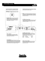
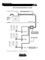
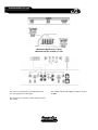
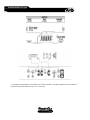
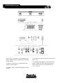
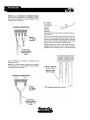
ZX475Ti Web Manual
September 7, 1999
TABLE OF CONTENTS
Features
02
Specifications
03
Operational Details
04-05
System Design, PowerFlow tm System
06-07
System Design, Examples
08-15
Installation, Mounting
16
Installation, Power & Speaker Connections
17
Installation, Input Sensitivity & Bass Adjustment
18
19-20
Trouble-Shooting
21
Warranty Information
ZXTi amp manual
pg.01
FEATURES
• TCCHtm Thermal Convection Cooled Heatsink. This proprietary design uses a variable speed
fan to ensure that the ZXTi keeps its cool when the music gets hot!
• High-current Triple Darlington output stage. This tried and true topology is the standard for
outstanding dynamic peak output performance
• TAIMtm Timed Acoustically Integrated Muting. Ensures dead silent turn on & off. No clicks, pops
or buzzes
• Tri-lineartm capability allows simultaneous stereo and bridged operation
• Output current sensing allows the ZXTi to automatically optimize the power supply and output
stage to reliably operate at impedances as low as 2 ohms bridged or 1 ohm stereo
• Intuitive crossover configuration switch assures easy initial setup
• 24dB per octave, high pass or low pass crossover. Continuously variable from 40 Hz to 8 kHz front
and 40 Hz to 800 Hz rear
• Auxiliary outputs route high pass, low pass or full range signals to another amplifier
• Twin-Ttm Bass Boost circuit provides up to 18dB of boost at 45 Hz
• Superbritetm Tri-LED power-on indicator
• Independent Thermal and Overload protection LED indicators
• Custom formed chassis with unique Titanium finish
• 24kt gold plated power and speaker terminals
• 2-ounce copper, double-sided G10 glass-epoxy printed circuit boards
• Replaceable insulated mounting feet
• Audiophile grade capacitors and 1% tolerance metal film resistors throughout the audio path
• Optional LPL44tm Low Pass Level controller allows the driver to adjust bass volume from the
driver’s seat
• Optional RDDPtm Remote Diagnostic Display Panel uses two tri-color LED’s allowing the driver to
monitor the amplifier’s battery voltage, power-on, thermal and overload status
• Optional SDTtm Superior Digital Technology allows the driver to monitor the amplifier’s battery
voltage with a vacuum florescent display along with a tri-color LED indicating power-on, thermal
and overload status
ZXTi amp manual
pg.02
SPECIFICATIONS
Continuous Output Power at 1% THD (Wrms):
ZX475Ti
Into 4 ohms Stereo @ 12.5 Vdc (IASCA/USAC)
Into 4 ohms Stereo @ 14.4 Vdc
Into 2 ohms Stereo @ 14.4 Vdc
Into 4 ohms Bridged @ 14.4 Vdc
Minimum Speaker Load, Bridged
Minimum Speaker Load, Stereo
Recommended Fuse Size, Stereo 4 ohms / Stereo 2 ohms / Bridged
Continuous Current Draw @ Full Power *
Peak Current Draw @ Full Power **
Dimensions, Chassis (inches)
Dimensions, Overall (inches)
Total Harmonic Distortion
Signal to Noise Ratio (A-weighted)
Frequency Response
Bass Boost
Crossover Frequency Range
Crossover Slope
Input Sensitivity
Input Impedance
Input Voltage Range
Power Supply Operating Range
Typical current draw at idle
18 x 4
75 x 4
150 x 4
250 x 2
2 ohms
1 ohm
60 / 80 / 80 amp
60 amps
85 amps
15.00 L x 9.00 W x 2.25 H
16.00 L x 10.00 W x 2.25 H
< 0.02 %
> 100 dB
+/- 1 dB, 20 Hz to 20 kHz
0 to +18 dB @ 45 Hz
40 Hz to 8 kHz
24 dB per octave
200 millivolts to 6 volts
> 30 kohms
0.2 volts to 6 volts
10.5 Vdc to 15.5 Vdc
< 3 amps
*Average continuous current draw when playing typical music material.
**Average peak current needed for musical peaks (<20ms) when playing typical music material.
Due to ongoing research and development, features, specifications and availability are subject to change without notice.
ZXTi amp manual
pg.03
OPERATIONAL DETAILS
220
160
300
450
110
40
800
ZXTi amp manual
pg.04
OPERATIONAL DETAILS
ZXTi amp manual
pg.05
SYSTEM DESIGN
ZXTi amp manual
pg.06
SYSTEM DESIGN
ZXTi amp manual
pg.07
SYSTEM DESIGN examples
Minimum bridged load is 2 ohms.
Minimum load per channel is 1 ohm.
The front crossover frequency control determines the
XS62's highpass frequency independently of the XS124
and rear speakers.
The rear crossover frequency control determines the
XS124's lowpass frequency and auxiliary output's highpass frequency.
Use the LPL44 to control the XS124's volume from the
driver's seat.
* For single preamp headunits, set the input select
switch to FRONT. This allows signals from the front
inputs to reach the rear crossover without the use
of “Y” connectors.
The auxiliary outputs send highpass signals to another
amplifier.
ZXTi amp manual
pg.08
SYSTEM DESIGN examples
Minimum bridged load is 2 ohms.
Minimum load per channel is 1 ohm.
The front crossover frequency control determines the
XS130's highpass.
Use the LPL44 to control the auxiliary output's volume
from the driver's seat.
The bandpass signal for the XS84’s midbass is created
between the front and rear crossover frequency settings.
NOTE: If connecting tweeters to the front outputs, set
the frequency multiplier switch to X10. This multiplies
the front crossover's frequency range by a factor of ten.
The range becomes 400 to 8kHz.
The rear crossover frequency control determines the
auxiliary output's lowpass frequency.
The auxiliary output sends lowpass signals to another
amplifier.
ZXTi amp manual
pg.09
SYSTEM DESIGN examples
Minimum bridged load is 2 ohms.
Minimum load per channel is 1 ohm.
The rear crossover frequency control determines the
crossover frequencies of all outputs.
The auxiliary output sends highpass signals to another
amplifier.
Use the LPL44 to control the volume of both front and
rear outputs.
ZXTi amp manual
pg.10
SYSTEM DESIGN examples
Minimum bridged load is 2 ohms.
Minimum load per channel is 1 ohm.
The front crossover frequency control determines the
XS62's highpass frequency independently of the XS69’s
and auxiliary outputs.
The rear crossover frequency control determines the
XS69's highpass frequency and auxiliary output's
lowpass frequency.
Use the LPL44 to control the auxiliary output's volume
from the driver's seat.
* For single pre-amp headunits, set the input select
switch to FRONT. This allows signals from the front
inputs to reach the rear crossover without the use of
“Y” connectors.
The auxiliary output sends lowpass signals to another
amplifier.
ZXTi amp manual
pg.11
SYSTEM DESIGN examples
* For single pre-amp headunits, set the input select switch to FRONT. This allows signal from the front inputs to
reach the rear channels without the use of “Y” connectors.
ZXTi amp manual
pg.12
SYSTEM DESIGN examples
The front crossover frequency control determines the
XS62's highpass frequency independently of the XS124
and rear speakers.
The rear crossover frequency control determines the
XS124's lowpass frequency.
Use the LPL44 to control the XS124's volume from the
driver's seat.
* For single preamp headunits, set the internal select
switch to FRONT. This allows signals from the front
inputs to reach the rear crossover without the use
of “Y” connectors.
The auxiliary outputs send full range signals to another
amplifier.
ZXTi amp manual
pg.13
SYSTEM DESIGN examples
The front crossover frequency control determines the
XS62's highpass frequency.
The auxiliary outputs send bandpass signals to another
amplifier.
The rear crossover frequency control determines the
XS124's lowpass frequency.
Use the LPL44 to control the XS124's volume from the
driver's seat.
The bandpass signal for the XS84 midbasses is created
between the front and rear crossover frequency settings.
ZXTi amp manual
pg.14
SYSTEM DESIGN examples
The auxiliary outputs send lowpass signals out to the
Bass Cube and then back into the front inputs.
The front crossover frequency control determines the
XS62's highpass frequency and the XS124's lowpass
frequency.
NOTE: Locating the Bass Cube in this position of the
signal flow allows only the low pass signal for the XS124
to be boosted. The XS62’s high pass signal will be
unaffected by the Bass Cube’s boost.
Use the LPL44 to control the XS124's volume from the
driver's seat.
ZXTi amp manual
pg.15
INSTALLATION
ZXTi amp manual
pg.16
INSTALLATION
ZXTi amp manual
pg.17
INSTALLATION
ZXTi amp manual
pg.18
TROUBLE-SHOOTING
SYMPTOM
POSSIBLE CAUSE
SOLUTION
No output and Power-on
LEDs are off
No battery, ground, or remote
connection
Verify that the B+, B-, and remote turn-on
terminals are properly connected and that the
headunit is turned on. Use a DC voltmeter to
check for 12 volts between the ground terminal
and the B+ terminal. Also, check between the
ground terminal and the remote turn-on terminal.
Blown or melted power fuse
Use an ohmmeter to verify that the fuse has
continuity between its ends. Disconnect the main
B+ cable from the battery and the inputs of all
devices in the system (including capacitors). Use
an ohmmeter to check for a short between the
power cable system and the vehicle's chassis.
Correct any short and install a new fuse. Replace
only with the same rating and type of fuse.
No signal from the head unit or
previous signal processor
Use an AC voltmeter to check for voltage at the
headunit or processor's preamp outputs. The
level should fluctuate with peaks in the music.
An analog gauge works well for this test.
Faulty input signal cables
Use an AC voltmeter to check for voltage at the
signal cables' outputs. Try substituting different
signal cables.
Faulty speaker or speaker cables
Try substituting another speaker or cables.
Clipped input signal feeding the
amplifier or signal processor
Make sure the headunit and all other components
are not producing a clipped signal. Most headunits clip their own output above 7/8 volume.
Distorted signals coming into the amp will sound
distorted at any input sensitivity setting.
Amplifier or signal processor's input
sensitivity too high
Lower input sensitivity (counterclockwise).
Setting the sensitivity too high causes distortion.
Distortion causes speakers to rapidly overheat
and can result in speaker failure.
Poor ventilation
Check for a poor mounting location that allows
hot air to be re-circulated within the heatsink.
Check for blocked input or exhaust openings.
Total speaker impedance is too low
causing excessive heat.
Re-wire speakers to raise the total impedance
seen by the amp. Minimum impedance is 2 ohms
bridged or 1 ohm stereo.
No output and power-on
LEDs are on
Distorted sound
Amplifier cuts off when
driven to high output
levels. Thermal protection
circuit activated (yellow
LED on).
ZXTi amp manual
pg.19
TROUBLE-SHOOTING
SYMPTOM
POSSIBLE CAUSE
Amplifier cuts off when
driven to high output
levels. Overload circuit
activated (red LED on).
Excessive output current is the only
thing that can cause the Overload
LED to light. There are only a few
possible causes:
SOLUTION
A damaged speaker cable touching
the vehicle chassis, speaker cables or
speaker tinsel leads touching each
other, or damaged speaker voice coil.
With the speaker wires disconnected from the
amp, use an ohmmeter to check for a short from
any speaker cable to chassis ground. Check the
DC resistance of the speaker's voice coil. It
should be close to the speaker's nominal impedance specification and should fluctuate when the
cone is touched. Visually check each speaker for
damaged tinsel leads, or other broken parts.
Smell the speaker's magnet area for a burned
scent indicating a damaged voice coil.
Damaged passive crossover
components.
Visually examine inductors, capacitors and
resistors for signs of heat stress, water, or
physical damage. Use a soldering iron to touch
up connections to the crossover circuit board.
Try substituting a different crossover network.
Total speaker impedance is too low
causing excessive output current.
Re-wire speakers to raise the total impedance
seen by the amp.
Defective output transistor inside the
amplifier
This condition will cause the overload LED to
stay lit without speaker wires connected to the
amplifier. The amplifier must be returned to an
authorized service center for repair.
Authorized Phoenix Gold Service Centers
USA
Phoenix Gold Factory
877.745.3782
Canada
Trends Electronics
604.988.2966
ZXTi amp manual
pg.20
LIMITED WARRANTY
Phoenix Gold International, Inc. (or "Phoenix Gold") warrants its products against defects in
materials and workmanship for a limited period of time.
For a period of one (1) year from date of original purchase, we will repair or replace the electronic
product, at our option, without charge for parts and labor. The limited warranty period is EXTENDED
to three (3) years from date of original purchase if the product was originally installed by an
authorized Phoenix Gold electronics dealer and accompanied by a valid sales receipt showing a
charge for installation. Customer must pay all parts and labor charges after the limited warranty
period expires. The limited warranty period for factory refurbished products expires after ninety (90)
days from date of original purchase. This limited warranty applies only to purchases from authorized
Phoenix Gold Electronics and Speaker retailers.
This limited warranty is extended only to the original purchaser and is valid only to consumers in
the United States. Consumers are required to provide a copy of the original sales invoice from an
authorized Phoenix Gold dealer when making a claim against this limited warranty. This limited
warranty only covers failures due to defects in materials or workmanship that occur during normal
use. It does not cover failures resulting from accident, misuse, abuse, neglect, mishandling,
misapplication, alteration, faulty installation, modification, service by anyone other than Phoenix
Gold, or damage that is attributable to Acts of God. It does not cover costs of transportation to
Phoenix Gold or damage in transit.
This warranty will become void if the serial number identification has been wholly or partially
removed, altered or erased. Repair or replacement under the terms of this warranty does not
extend the terms of this warranty.
Should a product prove to be defective in workmanship or material, the consumer's sole remedies
will be repair or replacement as provided under the terms of this warranty. Under no circumstances
shall Phoenix Gold be liable for loss or damage, direct, consequential or incidental, arising out of the
use of or inability to use the product. There are no express warranties other than described above.
ZXTi amp manual
pg.21