1
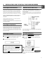
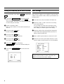
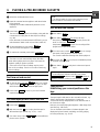
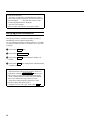
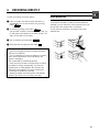
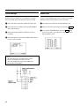
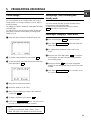
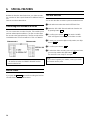
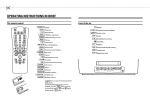
OPERATING INSTRUCTIONS PHILIPS TL960A5T
Power supply: AC 120V, 60 Hz only
If the unit is to be left unattended for a long period and it is not
intended to use the unit, it is recommended that the unit be
completely switched off by removing the plug.
This digital apparatus does not exceed the Class A limits
for radio noise emissions from digital apparatus as set
out in the Interference-causing equipment standard
entitled "Digital Apparatus", ICES-003 of the Department
of Communications.
Illustrated below is molded on the back of your unit.
This symbol warns the user that uninsulated
voltage within the unit may have sufficient magnitude to cause electric shock. Therefore, it is
dangerous to make any kind of contact with any
inside part of this unit.
This symbol alerts the user that important literature concerning the operation and maintenance
of this unit has been included. Therefore, it should
be read carefully in order to avoid any problems.
CAUTION: TO REDUCE THE RISK OF ELECTRIC SHOCK, DO
NOT REMOVE COVER (OR BACK), NO USER-SERVICEABLE
PARTS INSIDE. REFER SERVICING TO QUALIFIED SERVICE
PERSONNEL.
WARNING: TO PREVENT FIRE OR ELECTRIC SHOCK, DO
NOT EXPOSE THIS APPLIANCE TO RAIN OR MOISTURE.
Warning: This equipment has been tested and found to comply
with the limits for a Class A digital device, pursuant to Part 15
of the FCC Rules. These limits are designed to provide
reasonable protection against harmful interference when the
equipment is operated in a commercial environment. This
equipment generates, uses, and can radiate frequency and, if
not installed and used in accordance with the operating
instructions manual, may cause harmful interference to radio
communications.
Operation of this equipment in a residential area is likely to
cause harmful interference in which case the user will be
required to correct the interference at his own expense.
CAUTION: CHANGES OR MODIFICATIONS NOT EXPRESSLY
APPROVED BY THE PARTY RESPONSIBLE FOR COMPLIANCE
COULD VOID THE USER’S AUTHORITY TO OPERATE THE
EQUIPMENT.
Safety
• Should any solid object or liquid fall into the cabinet, turn
off the unit and have it checked by qualified personnel
before operating it any further.
• To disconnect the power cord, pull it out by the plug.
Never pull the cord itself.
Installation
• Choose a location in which air can pass through the
ventilation holes in the bottom, top and back of the unit to
prevent it from overheating.
• Do not install the unit near sources such as radiators or air
ducts or in a place subject to direct sunlight, excessive
dust, mechanical vibrations or shock.
• Never bring a magnet or magnetized object near the VCR
because it will adversely affect the performance of the
VCR.
• Do not install the unit in an inclined position.
The unit is designed for operation in a horizontal position.
Operation
• Condensation
If you pour a cold liquid into a glass, water vapor in the air
will condense on the surface of class.
This is the condensation moisture.
Condensation on the head drum, one of the most crucial
parts of the VCR, will cause damage to the tape.
The VCR should not be operated for at least 2 hours after
being removed from a cold to a hot environment to avoid
condensation from occurring on the head drum.
Cleaning
• Be careful; when surface of the case is wiped with a
volatile agent such as benzine, alcohol, thinner, etc., or a
chemically processed cloth, the surface finish may be
degraded or its coating may peel off.
Repacking
• It is wise to save the packing materials and box in case
you ever need to ship or store your unit.
1
IMPORTANT SAFEGUARDS
6
Overloading - Do not overload wall outlets and
extension cords as this can result in a risk of fire
or electric shock. Overloaded AC outlets and
extension cords are dangerous, and so are frayed
power cords, damaged or cracked wire insulation
and broken plugs. They may result in a shock or
fire hazard. Periodically examine the cord and
have it replaced by your service technician if
appearance indicates damage or deteriorated
insulation.
7
Power-Cord Protection - Power-supply cords
should be routed so that they are not likely to be
walked on or pinched by items placed upon or
against them, paying particular attention to cords
at plugs, convience receptacles, and the point
where they exit from the appliance.
8
Ventilation - Slots and openings in the cabinet are
provided for ventilation to ensure operation of the
video product and to protect it from overheating.
These openings must not be blocked or covered.
The openings should never be blocked by placing
the video product on a bed, sofa, rug, or other
similar surface. This video product should never
be placed near or over a radiator or heat register.
This video product should not be placed in a
built-in installation such as bookcase or rack
unless proper ventilation is provided or the video
product manufacturer’s instructions have been
followed.
9
Attachments - Do not use attachments unless
recommended by the video product manufacturer
as they may cause hazards.
In addition to the careful attention devoted to quality standards in the manufacture of your video product, safety is a
major factor in the design of every instrument. But, safety is
your responsibility too.
These pages list important information that will help to assure
your employment and proper use of a Video Cassette Recorder
and accessory equipment. Please read it carefully before
operating your video product and keep it in a handy place for
future reference.
INSTALLATION
Caution:
To prevent electrical shock, match wide blade
of plug to wide slot, fully insert.
1
Read and Follow Instructions - All the safety and
operating instructions should be read before the
video product is operated. Follow all operating
and use instructions.
2
Retain Instructions - The safety and operating
instructions should be retained for future reference.
3
Head Warnings - Comply with all warnings on the
video product and in the operating instructions.
4
Grounding or Polarization - The sets concerned
should be operated with the mains cable supplied.
5
Power Sources - This video product should be
operated only from the type of power source
indicated on the marking label. If you are not sure
of the type of power supply to your home, consult
your video dealer or local power company. For
video products intended to operate from battery
power, or other sources, refer to the operating
instructions.
2
Caution: Maintain electrical safety. Powerlines operated
equipment or accessories connected to this unit should bear
the UL listing mark or CSA certification mark on the accessory
itself and should not have been modified so as to defeat the
safety features. This will help avoid any potential hazard from
electric shock or fire. If in doubt, contact qualified personnel.
10
Water and Moisture - Do not use this video
product near water - for example, near a bath tub,
wash bowl, kitchen sink, or loundry tub, in a wet
basement, or near a swimming pool, and the like.
11
Accessories - Do not place this video product on
an unstable cart, stand, tripod, bracket, or table.
The video product may fall, causing serious injury
to a child or adult, and serious damage to the
appliance. Use only with a cart, stand, tripod,
bracket, or table recommended by the manufacturer, or sold with the video product. Any mounting of the product should follow the
manufacturer’s instructions, and should use a
mounting accessory recommended by the manufacturer.
11A
An appliance and cart combination should be
moved with care. Quick stops, excessive force,
and uneven surfaces may cause the appliance
and cart combination to overturn.
16
Conditions Requiring Service - Unplug this video
product from the wall outlet and refer servicing to
qualified service personnel under the following
conditions.
a. When the power-supply cord or plug is damaged.
b. If liquid has been spilled, or objects have fallen
into the video product.
c. If the video product has been exposed to rain or
water.
d. If the video product does not operate normally
by following the operation instructions. Adjust
only those controls that are covered by the
operating instructions. Improper adjustment of
other controls may result in damage and will often
require extensive work by a qualified technician
to restore the video product to its normal operation.
e. If the video product has been dropped or the
cabinet has been damaged.
f. When the video product exhibits a distinct
change in performance - this indicates a need for
service.
17
Replacement Parts - When replacement parts are
required, have the service technician verify that
the replacements he uses have the same safety
characteristics as the original parts. Use of
replacements specified by the video product
manufacturer can prevent fire, electric shock or
other hazards.
18
Safety Check - Upon completion of any service or
repairs to this video product, ask the service
technician to perform safety checks recommended by the manufacturer to determine that the
video product is in save operating condition.
USE
12
13
14
Cleaning - Unplug the video product from the wall
outlet before cleaning. Do not use liquid cleaners
or aerosol cleaners. Use a damp cloth for cleaning.
Object and Liquid Entry - Never push objects of
any kind into this video product through openings
as they may touch dangerous voltage points or
short-out parts that could result in a fire or
electric shock. Never spill liquid of any kind on the
video product.
Lightning - For added protection for this video
product during a lightning storm, or when it is left
unattended and unused for long periods of time,
unplug it from the wall outlet. This will prevent
damage to the video product due to lightning and
power-line surges.
SERVICE
15
Servicing - Do not attempt to service this video
product yourself as opening or removing covers
may expose you to dangerous voltage or other
hazards. Refer all servicing to qualified service
personnel.
3
4
Congratulations on your purchase. You are now the
owner of a Time Lapse Recorder (TLR), one of the most
advanced and simple-to-use VHS standard video recorders on the market.
We’re sure you can hardly wait to use it. However, it’s
worth taking a moment to read through the operating
manual. That way you’ll find out how to use it properly.
Whatever button you press, you won’t damage your video
recorder, so you can quite safely practice operating it.
Please also read the chapter on safety.
Contents
1.
SUMMARY OF BUTTONS, CONTROLS AND SOCKETS . 6
The front of the appliance . . . . . . . . . . . . . . . . . . . . . . . . . . 6
The rear of the appliance . . . . . . . . . . . . . . . . . . . . . . . . . . 6
2.
INSTALLATION. HOW TO INSTALL YOUR VIDEO
RECORDER. . . . . . . . . . . . . . . . . . . . . . . . . . . . . . . . . . . . . . . .
Connecting the television/monitor . . . . . . . . . . . . . . . . . . .
Connecting to an input source . . . . . . . . . . . . . . . . . . . . . .
Connecting to the mains . . . . . . . . . . . . . . . . . . . . . . . . . . .
Connections on the control socket . . . . . . . . . . . . . . . . . .
On-Screen Display (OSD) . . . . . . . . . . . . . . . . . . . . . . . . . .
Setting the time/date on the video recorder . . . . . . . . . .
Basic settings . . . . . . . . . . . . . . . . . . . . . . . . . . . . . . . . . . . .
•
•
•
•
Dangerous high voltage inside video recorder. Do not
open the set. The appliance does not contain any
components that can be repaired by the customer. When
the appliance is connected to the mains there are some
components that are constantly operational. You can only
switch it off completely by unplugging it from the mains.
Note that this video recorder is designed for a power
supply of 110-120V/60Hz.
Ensure that air can flow freely through the ventilation
openings on the appliance. Do not place the appliance on
soft surfaces.
Do not place the appliance near a heat source (e.g.:
radiator).
Ensure that no objects or liquids are allowed to penetrate
the appliance. If liquid is spilt on it, unplug it immediately
from the mains and call the customer service department.
7
7
7
7
7
7
8
8
3.
PLAYING A PRE-RECORDED CASSETTE . . . . . . . . . . . . . . 9
Fast forward and rewind . . . . . . . . . . . . . . . . . . . . . . . . . . . 9
The time-lapse/picture search function . . . . . . . . . . . . . . 9
Still picture/slow motion . . . . . . . . . . . . . . . . . . . . . . . . . . . 9
Tape position. . . . . . . . . . . . . . . . . . . . . . . . . . . . . . . . . . . . . 9
Rectifying picture disturbances. . . . . . . . . . . . . . . . . . . . 10
4.
RECORDING DIRECTLY . . . . . . . . . . . . . . . . . . . . . . . . . . .
Erase protection . . . . . . . . . . . . . . . . . . . . . . . . . . . . . . . . .
Alarm settings . . . . . . . . . . . . . . . . . . . . . . . . . . . . . . . . . . .
Alarm chart . . . . . . . . . . . . . . . . . . . . . . . . . . . . . . . . . . . . .
11
11
12
12
5.
PROGRAMMING RECORDINGS . . . . . . . . . . . . . . . . . . . .
TIMER settings . . . . . . . . . . . . . . . . . . . . . . . . . . . . . . . . . .
Interrupting a TIMER recording and standby mode . . .
Checking or changing a TIMER block . . . . . . . . . . . . . . .
13
13
13
13
6.
SPECIAL FEATURES . . . . . . . . . . . . . . . . . . . . . . . . . . . . . .
Connecting two recorders in series . . . . . . . . . . . . . . . .
Record Check . . . . . . . . . . . . . . . . . . . . . . . . . . . . . . . . . . .
The lock function . . . . . . . . . . . . . . . . . . . . . . . . . . . . . . . . .
14
14
14
14
7.
TROUBLESHOOTING . . . . . . . . . . . . . . . . . . . . . . . . . . . . . 15
8.
SAFETY TIPS . . . . . . . . . . . . . . . . . . . . . . . . . . . . . . . . . . . .
Recommended servicing . . . . . . . . . . . . . . . . . . . . . . . . . .
Technical data . . . . . . . . . . . . . . . . . . . . . . . . . . . . . . . . . . .
Accessories supplied . . . . . . . . . . . . . . . . . . . . . . . . . . . . .
Safety tips
•
Page
16
16
17
18
5
1.
SUMMARY OF BUTTONS, CONTROLS AND SOCKETS
You will find exact details of the various functions in the corresponding chapters.
The front of the appliance
0-9
Digit buttons
S/CL
Select/Delete
OK
Confirm
MENU/TRACKING
TU
JEJECT
GPLAY
Menu/Tracking position
nREC.
RSTILL
hSTOP
mSTANDBY
Record
Still picture
Stop
Switch off
Up/Plus, Down/Minus
!
Rewind
Cassette eject
"
Fast forward
Playback
$
Jog (inner dial)
The rear of the appliance
4
EXT 1
AUDIO IN
AUDIO OUT
VIDEO IN
VIDEO OUT
Mains socket
Scart socket (AV Euroconnector)
CINCH audio input socket
CINCH audio output socket
BNC video input socket
BNC video output socket
Control socket:
Pin1 ALARM IN
Pin2 SERIAL IN
Pin3 ALARM RESET/REC OUT
Pin4 GND (earth)
Pin5 ALARM OUT
Pin6 SERIAL OUT
Pin7 CAM. SW. OUT
Pin8 TAPE END OUT
Pin9 RECORD CHECK
6
2.
INSTALLATION. HOW TO INSTALL YOUR VIDEO RECORDER.
Connecting the television/monitor
Connections on the control socket
Connect your monitor/television set to the corresponding
VIDEO OUT socket on the video recorder with a BNC cable.
Connect your monitor/television set to the corresponding
AUDIO OUT socket on the video recorder with a cinch cable.
Do not connect any external voltage sources to the 9
contacts on the control terminal as this could damage the
inputs and outputs.
To connect the wire, remove 5 - 10 mm of the insulation and
insert the bare wire into the relevant opening right up to the
insulation.
Instead of using the BNC-cable you can also use the scart
cable as a connection between scart socket and television/monitor.
Select programme number ’EXT’, ’0’ or ’AV’ on your monitor/television set to play recordings.
Consult the operating manual for your monitor/television set
for further information.
Connecting to an input source
Connect your video source (e.g.: camera) to the corresponding
VIDEO IN socket on the video recorder with a BNC cable.
Connect your audio source (e.g.: camera with a microphone)
to the corresponding AUDIO IN socket on the video recorder
with a CINCH cable.
Connecting to the mains
See "Technical Data" for more information on the signal level
at the control terminal.
On-Screen Display (OSD)
1 Press button
1 Connect the appliance end of the power cable into mains
socket
4
at the rear of the video recorder.
MENU/TRACKING with the recorder in
STOP mode to call up the On-Screen Display (OSD).
2 Press buttons
TU
to go to the required line in the
main menu.
2 Plug the other plug into the wall socket.
MAIN MENU
20:00
Note:
* The video recorder switches on automatically when
you insert a cassette or press button mSTANDBY .
* When ’SET CLOCK’ appears in the display or if the
clock time flashes in the display, e.g.:’20:00, you must set
the clock.
* When ’PL’ (POWER LOSS) appears on the screen,
press button S/CL .
CLOCK SETTINGS
BASIC SETTINGS
ALARM SETTINGS
ALARM MEMORY
TIMER SETTINGS
HEAD USAGE TIME
000000H
-----------------------vw
OK/MENU
3 If there is more than one choice, select the one you
require by pressing button
4 To confirm, press button
S/CL
OK
.
.
5 To exit from the OSD, press button
MENU/TRACKING
.
The bottom line of the screen displays information on
operation.
7
Setting the time/date on the video recorder Basic settings
TU
In all the steps below, press buttons
0-9 .
or digit buttons
Define the basic settings on your appliance: input via SCART
or BNC socket, position of OSD, camera synchronisation and
locking function.
1 Press button
MENU/TRACKING . Select CLOCK SETTINGS in the main menu. Now press button OK .
The word ’MENU’ will appear in the display on the video
recorder during the next steps.
2 Set the current time (TIME).
When you enter minutes, seconds will automatically be
set to ’0’.
3 Now press button
again.
Set the current date (DATE).
OK
5 Now press button
OK
again.
Now set the current year (YEAR).
OK
MENU/TRACKING
again, followed by
. You have now finished setting the
time and date.
7 Press button
MENU/TRACKING
to exit from the main
menu.
4 Select ’artificial synchronisation’ (V SYNC) INT or EXT.
5 Select the lock function (SEC CODE) with (ON) or (OFF).
See the chapter ’Special Features’ for more information.
BASIC SETTINGS
REC SOURCE
RS 232
OSD
V SYNC
BEEP
PLAY MODE
BNC
ON
R-BOTTOM
INT
N
24HA
SEC CODE
OFF
-----------------------vw/S
OK/MENU
TIME :
13:45
DATE :
MONTH:
YEAR :
28
02
98
-----------------------vw/0-9
OK/MENU
8
source (REC SOURCE).
If no recording source has been connected or if the
recording source has been incorrectly selected in the
basic settings, ’NO VIDEO’ appears in the display.
(L-BOTTOM), bottom right (R-BOTTOM), top left (L-UPPER), top right (R-UPPER), OFF.
again.
Now set the current month (MONTH).
6 Press button
2 Select the ’SCART’ or ’BNC’ socket as the recording
3 Select the position of the OSD (OSD POS): bottom left
OK
4 Now press button
1 In the main menu, select the ’BASIC SETTINGS’ line.
Note:
* Always leave the video recorder connected to the
mains so as not to lose the basic settings.
3.
PLAYING A PRE-RECORDED CASSETTE
1 Switch the monitor/television set on.
2 Insert the cassette into the appliance with the window
facing upwards.
Inserting the cassette automatically switches on the
appliance.
Note:
* The picture quality is poorer when using the picture
search function. The sound is switched off.
Still picture/slow motion
3 Press button GPLAY .
The word ’PLAY’ will appear in the display, along with the
current total recording time for time-lapse recordings,
e.g.: 24h.
In the 24h mode, in the menu BASIC SETTINGS, you can
select between ’24HA’ (audio on) and ’24H’ (audio off).
4 To interrupt playback, press button hSTOP .
1 Press button GPLAY .
2 Press button
RSTILL
. The picture will stop.
Every time you press RSTILL again, the picture will
move on one frame.
Keep button RSTILL pressed. The recording will be
played back in super slow motion.
The word ’STOP’ will appear in the display.
3 Turn outer rotary control
5 To remove the cassette, press button
JEJECT
.
Note:
* The video recorder automatically cleans the video
heads before playing back every tape. This keeps the
playback quality as good as possible.
* The sound on 12h + 24h recordings may be poorer
than on 2h recordings. There is no sound on other long
time recordings.
!
"
. You can change
the speed of the playback in several stages.
The sound is switched off during slow motion playback.
4 Turn inner dial $ . You can play back individual pictures
forwards and backwards.
5 Press button GPLAY to play back at the normal speed
again.
Note:
* If the still picture vibrates vertically, press button
MENU/TRACKING and then button
TU until the vibration is minimal. Confirm by pressing button OK .
Fast forward and rewind
1 To stop the tape, press the hSTOP button. Turn outside
" to the left or right. The tape
rotary control !
will be fast forwarded or rewound at high speed.
2 Press button hSTOP as soon as you have found the
required tape position.
The time-lapse/picture search function
1 Press button GPLAY .
2 With the inner dial $ you can play back the tape in
different time-lapse speeds, e.g.: 12, 24, ... hours.
3 Turn outer rotary control
!
"
Tape position.
Establishing your current position on the
tape.
The tape length is indicated on the cassette in minutes, e.g.:
’E120’ is 120 minutes of playing time (= 2:00 hours).
You will find the tape length printed on the left hand side of
the front narrow edge.
However, the actual playing time might be a little longer than
specified (e.g.: 2:05 hours).
You can read the exact number of minutes played in the
display during fast forward, rewinding, recording, playing
back and pause/stop, e.g.: ’U1:25’.
to select different
picture search speeds.
9
Some more useful tips:
* The video recorder has to calculate the tape position
when a new cassette is inserted. The video recorder will
therefore display ’ - : - -’ first,and after a few seconds
the used playing time will be displayed.
* Only use T120 cassettes.
Other cassettes will indicate a wrong tape position.
Rectifying picture disturbances.
Every time you insert a cassette in the video recorder, it
automatically sets the right tracking position.
You can adjust the automatic tracking position for recordings
recorded on another machine. If you need to do so, proceed
as follows:
1 Press button GPLAY twice.
2 Press button
MENU/TRACKING
3 Press button
TU
.
until the playback quality is op-
timised.
4 Press button
OK
. This setting will be retained until the
cassette is removed.
Note:
* Cleaning function: Select the 3h-playback mode. During playback, hold the MENU/TRACKING button for several seconds. The video head cleaning function starts.
* Some cassettes have poor picture and sound quality.
This is not a malfunction on your video recorder.
* If the picture jumps vertically, switch the ’V SYNC’
function in BASIC SETTINGS to (INT).
* If playback is poor (12h + 24h), press button S/CL .
10
4.
RECORDING DIRECTLY
To make a recording, proceed as follows:
Erase protection
1 Insert a cassette. The video recorder will switch on
automatically. You can also switch it on by pressing
button hSTOP .
2 To start the recording, press button
nREC.
.
The word ’REC’ and the current total recording time, e.g.:
2h, will appear in the display on the video recorder. The
video recorder will start recording.
To prevent an important recording from being deleted accidentally, you can remove the erase protection tab on the
narrow side of the cassette with a screwdriver.
To undo the erase protection, seal the gap again with
adhesive tape.
3 Stop recording by pressing button hSTOP .
4 Select the total recording time with button $ .
Some general tips:
* If you have forgotten to insert a cassette, the display
will read ‚NO CASSETTE’.
* If you accidentally try to start recording on a cassette
that is erase protected, the word ’PROTECTED’ will
appear in the display.
The cassette will be automatically ejected.
* If the end of the cassette is reached during recording,
the appliance will stop automatically. If you have activated repeat recording (REPEAT REC), the tape will
wind back to the beginning. The video will then start
recording at the beginning of the tape.
* Existing recordings on the tape will be automatically
deleted if you make a new recording on the tape.
11
Alarm settings
Alarm chart
Defining the alarm settings on your appliance: automatic
alarm recording, alarm reset time and repeat recording.
To view a chart displaying the most recent alarm recordings
with their number, date and time, proceed as follows:
1 In the main menu, select the ’ALARM SETTINGS’ line.
1 In the main menu, select the ’ALARM MEMORY’ line.
2 Select the alarm recording function (ALARM ENABLE)
2 Select an alarm line. Start playback by pressing GPLAY .
(A2H, A12H, A24H, N).
3 If you want to delete all entries, press the S/CL button
3 Select the reset time (RESET TIME) after an alarm
recording.
for a few seconds. If you remove the cassette all entries
will be deleted as well.
4 Select the repeat record function (REPEAT REC) with (Y)
or (N) or ’NOT IF ALARM’.
ALARM SETTINGS
ALARM ENABLE
N
RESET TIME
5 MIN.
REPEAT REC
N
-----------------------vw/S
OK/MENU
Note:
* Alarms will only be recorded if there are alarm
sensors connected to your video recorder.
* Alarm recordings can only be interrupted by an
external alarm reset (RESET).
12
ALARMDATE
TIME
1 01.12.98 13:25
2 01.12.98 18:10
3 01.13.98 19:30
4 01.14.98 20:25
5 01.15.98 22:12
6 01.16.98 00:15
7 01.16.98 12:01
8 01.16.98 17:50
-----------------------vw/y
CL
MENU
5.
PROGRAMMING RECORDINGS
TIMER settings
Interrupting a TIMER recording and
standby mode
You can programme up to 7 TIMERS within any 31-day (1
month) period. You can select between a one-off, daily or
weekly recording.
The settings you made in the BASIC and ALARM SETTINGS
menu will apply.
You will then see a chart of all programmed TIMERS with
their dates, start times and stop times, recording speed,
TIMER on or off.
You cannot operate the video recorder manually while a
programmed recording is being made.
To interrupt the programmed recording, press button
hSTOP and hold for a few seconds.
Checking or changing a TIMER block
1 In the main menu select the ’TIMER SETTINGS’ line.
1 Press and hold button hSTOP for several seconds.
DATE START STOP MOD TIM
y ---:-- --:-- --- ---
2 Press button
MENU/TRACKING
. Select the TIMER SET-
TINGS menu.
3 The TIMER blocks will appear in time order on the
screen.
-----------------------vw
CL
OK/MENU
4 Now press one of the digit buttons
2 To activate a new TIMER line, press button
OK
.
3 To select the DATE, the START time and the STOP time,
0-9
press digit buttons
.
DATE START STOP MOD TIM
19
17:00 17:01 12H ON
0-9
to change the
recording date, start time, stop time, TIMER-activation
and recording speed.
5 Finally press button
OK . If you have changed the
settings, the new settings will now be stored in the video
recorder.
6 Press button
MENU/TRACKING
twice. The video record-
er is now in standby.
-----------------------v1
v2
v3 7
8
w4 S w5
w6 OK/MENU
4 Select the recording speed (’MOD’).
5 Switch the TIMER on or off (’TIM’).
6 When you have finished your entry in the TIMER line,
confirm with
OK
.
7 To delete a TIMER line, press button S/CL .
8 Press button
MENU/TRACKING twice. The video recorder is now in standby and cannot be operated.
Notes:
* If a timer is programmed, ’DATE’, ’START’, ’STOP’,
’TIMER’ will appear in the display on the video recorder.
13
6.
SPECIAL FEATURES
Besides the functions described above, your video recorder
has a number of other special features for additional ease of
use.
Find out more about them below.
The lock function
You can lock the video recorder to prevent unauthorised use.
1 In the main menu select the ’BASIC SETTINGS’ line.
Connecting two recorders in series
2 Select the ’SEC CODE’ line and switch the function ’ON’
You can connect two recorders in series. This enables you to
perform uninterrupted surveillance. The first recorder starts
the second at the appropriate time. The first recorder will be
in RECORD mode. The second will be in STOP or STANDBY.
by pressing button
S/CL
.
3 To confirm, press button
OK . The words ’LOCKED
XXXX’ will appear in the display on the video recorder.
4 To enter your personal 4-digit security number, use digit
buttons
0-9
.
5 To confirm, press button
OK
.
6 To unlock the video recorder, press any button and enter
your security number with digit buttons
The machine is now ready for use again.
Note:
* On the first recorder the ’REPEAT RECORD’ function
must be switched off.
Record Check
If you press the nREC. button while recording, the last few
seconds of the recording will be shown.
14
0-9
.
Note:
* If you have forgotten your number, contact your dealer
or customer service point.
7.
TROUBLESHOOTING
Problem
Possible cause
The video recorder does not react when you press
any buttons.
* No power.
* A programmed recording is currently being made.
* Technical fault - Disconnect from the mains for 30 seconds and
then reconnect. If that does not help, you can: 1. Disconnect from
the mains. 2. Press and hold button hSTOP on the machine and
reconnect to the mains. All the data memories will be reset
(deleted).
No playback from video recorder
* No recording on the cassette.
* The wrong VCR channel number on the television set has been
selected, or the channel has been set wrong.
* The connecting cable between the monitor/television set and the
video recorder has been disconnected.
Bad playback quality on video recorder
* Use TRACKING function if the recording was made on another
machine.
* Poor quality or worn cassette.
The programmed recording function does not work
* Time wrongly programmed.
* Time/date not properly set.
* A cassette with erase protection has been inserted.
15
8.
SAFETY TIPS
Precautionary safety measures/Tips
Recommended servicing
•
•
•
•
•
•
•
•
•
•
•
Do not take the appliance straight from a cold room into a hot
room or vice versa immediately after transportation. Do not use
in an extremely humid environment. To give the appliance time
to acclimatise, do not install the appliance for at least 3 hours
after unpacking.
Do not use the appliance in dusty rooms, near strong magnetic
fields or in places where it will be exposed to vibration.
We recommend disconnecting the appliance from the mains
during thunderstorms to prevent lightning damage.
There must be a vertical gap of at least 20 cm between the
video recorder and the television set/monitor.
Inserting fingers or foreign bodies into the cassette compartment can damage the mechanics of the appliance.
This video recorder operates with standard VHS cassettes.
To ensure that the picture quality on your video recorder is as
good as possible, only use branded VHS cassettes.
This machine is designed for longevity. The operating hours are
displayed in the main menu (HOUR METER). In order to ensure
that your video recorder runs smoothly, we recommend servicing it every 1000 hours as follows:
Operating hours
1000
2000
3000
4000
etc.
Transport system
1
1
1
1
A/C head
1
1
1
1
Upper drum
1
"
1
"
Lower drum
1
"
1
"
Capstan Axle
1
1
1
1
Capstan Motor
-
-
-
-
Pressure roller
1
"
1
"
-
"
-
"
Inspectionpoint
This operating manual is printed on recycled paper. This helps
to preserve our environment.
Use your local facilities for environmentally friendly disposal of
packaging.
This electronic appliance contains many materials that can be
recycled. Find out whether your old one can be recycled in any
way.
Cleaning the heads
1...
"...
•
•
16
Cleaning
Servicing, replacing components
The capstan motor and A/C head should also be replaced every
10,000 hours.
This table is only a rough guide to servicing. You should adapt
the actual servicing intervals according to the conditions in
which the video recorder is used.
Technical data
Signallevel on control socket
Connection
Signallevel
Note
Pin 1
ALARM IN
Alarm input
HIGH: 5V
LOW: GND
min. 0,5 sec.
Input active with LOW
signal level
Pin 2
SERIAL IN
Starting the recording
on a second video
recording
HIGH: 5V - 12V
LOW: GND
min. 0,5 sec.
Input active with LOW
signal level
Pin 3
RESET/REC OUT
Alarmreset
HIGH: 5V
LOW: GND
min. 0,5 sec.
Input active with LOW
signal level
Output active with HIGH
signal level
Pin 4
GND
Mass
Pin 5
ALARM OUT
Alarm output
HIGH: 12V
Iout = max. 50mA
Short circuit protected
Setting the menu in ALARM
SETTINGS
Output active with HIGH
signal level
Pin 6
SERIAL OUT
Output for starting a
second video recorder
HIGH: 12V
Iout = max. 50mA
Short circuit protected
10 sec.
Output active with LOW
signal level
Pin 7
CAMERA SW OUT
Camera switching pulse
HIGH: 5V
LOW: max. 0,8V
Internal pullup 5kOhm
4 frames after the recorded
frame
Output active with LOW
signal level
Pin 8
TAPE END OUT
Tape end warning
HIGH: min. 11V
Iout = max. 50mA
Short circuit protected
Pin 9
RECORD CHECK
HIGH: 5V - 12V
LOW: GND
15 Minutes be- EJECT or
fore end of tape REWIND
at least 0,5 sec.
Output active with LOW
signal level
Input active with LOW
signal level
17
•
•
•
•
•
•
•
•
•
•
•
•
•
•
•
•
Mains power 110 to 120V
Mains frequency 60Hz
Power consumption typically 15W (typically 9,5 W in standby)
Wind/Rewind time typically 95s for an E120
Ambient temperature during operation +10˚C to +35 ˚C
Relative humidity 30% to 80%
Recording: 2, 12, 24, 48, 72, 168, 336, 720, 960 hours
Operating position max. 15˚ inclination in all directions
Size 380 x 338 x 86 mm (incl. feet)
Weight approx. 4,6 kg
Video resolution VHS 240 lines
Audio (SP) 500Hz - 10KHz (8dB) in 2h mode
Power failure protection: 24 hours.
VIDEO IN/OUT socket: 1 V p-p, 3dB, 75 Ohm
AUDIO IN socket: -10dB, 50 kOhm
AUDIO OUT socket -6dB, less than 1kOhm
Accessories supplied
•
•
•
•
•
Operating instructions
Power cable
BNC cable (2)
Double CINCH cable
CINCH-BNC adapter (2)
To be able to identify your appliance if it is stolen, please enter
the serial number (PROD.NO.) in the illustration. You will find
the serial number on the type plate on the reverse of the
appliance. It will also be quicker for us to answer any
customer service queries if you can give the information on the
type plate when you contact us. You should therefore keep this
page in a safe place.
TYPE
VN xx
Printed in Hungary
18
TL960A5T
PROD.NR. . . . . .
Distributed by:
Philips Consumer Electronics Company
Knoxville Tennessee 37914