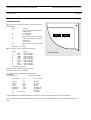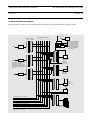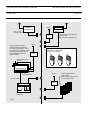
1
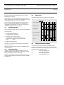
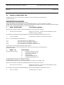
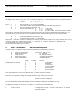
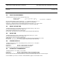
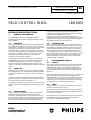
INSTALLATION
INSTRUCTIONS
DP 6000 DIGITAL PAGING SYSTEM
69
December 1997 Page 1 of 15
FIELD CONTROL PANEL
LBB 6005
For a detailed description of DP 6000 paging calls refer to
Installation Instruction No. 63 for the High Performance Control
Desk (LBB 5800).
holder, whereas in the latter, the PST holder must, within a
predetermined time, acknowledge that a call has been received by
pressing the Alarm Reset Button on the PST.
When the auto-scan facility is programmed and set for user
enable/inhibit, the auto-scan facility will be activated by pressing the
channel Auto-Scan key on the FCP, pressing Auto-Scan key again
this will disable the auto-scan activity and so on.
1.1
1.4
INSTALLATION INSTRUCTIONS
1
GENERAL INFORMATION
Description
Philips Personal Security System PS 6000 combines paging functions
with portable alarm facilities for people on the move in hazardous
environments or are liable to incur some personal risk. The system
is based upon Personal Security Transceivers (PST), a High
Performance Desk and a Field Control Panel (FCP). The system
incorporates security facilities such as manual alarm and automatic
system scanning. In addition, a detector circuit is built into the
transceiver which will initiate an alarm procedure when no
movement of the transceiver is detected.
Communication between the PST and the FCP is always via the
LBB 5800 Desk. Each FCP monitors the status of its own PSTs
programmed into the system. An FCP can be programmed to
monitor the PST’s fully automatically without any action by the
operator or PST holder, and also by manual confirmation of the PST
holder.
1.2
System size
Each Field Control Panel can cater for up to 16 PSTs and the PSTs
are programmed to react to their dedicated call buttons and LEDs
on that particular panel. Up to 31 FCPs can be interconnected via
the desk.
A High Performance Desk LBB 5800 can supply enough power to
support only one FCP. If more than one FCP is used in the system,
they must be powered via an external supply unit.
Field Alarm Calls
The FCP can be programmed to react to an Alarm Call from the
PST in several ways; When the Alarm LED lights, a Direct Call can
be transmitted to establish contact with the PST holder. This call
will be initiated by using the Direct Call Key for that channel. If no
action is taken by the operator within a predetermined time, a
preprogrammed alarm call can be automatically routed to another
PST. A built in delay timer can activate one to three relay outputs in
the FCP, which can be used to activate some other device e.g.
telephone exchange. The relay function can be programmed for
continuously ON or pulsed ON.
2
PROGRAMMING THE FCP
2.1
General
All programming of the FCP must be carried out via the LBB 5800
desk. The FCP must first be set “present” by the allocation of a
dedicated address and all the various functions required by the
customer must be done by further software programming. Only
one uninitialised FCP may be connected to the RS 422 line at any
given time.
When an uninitialised FCP is powered up, the top row of LEDs will
all blink slowly. When initialised, the FCP address LED will be
illuminated during power up. These are represented by the top two
rows of LEDs (1 - 31) reading from top left to bottom right. The
power LED in the top left corner will be illuminated. (Powering up
the desk with an FCP connected takes max. 60 sec.)
The RS 422 communication bus can be used to connect all the FCPs
together, in parallel, to the LBB 5800 Desk (see page 15 for system
set up).
2.2
1.3
When the Editor is opened, the program variables can be entered
via the keyboard and the desk bleeper gives an audible indication of
correct or incorrect entries.
System Scanning
The FCP can be programmed to scan the PST’s in the system at
preprogrammed intervals and check the status of each. An
automatic or an additional manual response from the PST to this
check call can be programmed, for each individual channel, into the
FCP. In the former instance, the PST will automatically send the
status information back to the FCP without disturbing the PST
Philips
Communication &
Security Systems
Editor
The Editor function of the desk is the means by which the system
variables are programmed into the FCP.
The normal sequence of programming the FCP is to first enter the
required MENU followed by the menu COMMAND DIGIT,
followed by the PROGRAM VARIABLE(S).
DP 6000 DIGITAL PAGING SYSTEM
INSTALLATION INSTRUCTION 69
December 1997
During programming, the desk display will show the program
information as it is entered.
Page 2/15
2.5
Bleep Tones
The following bleep tones can be heard during programming :
Use the DIRECT CALL key of the desk to select the correct FCP
number (if more than one connected ) the PROGRAM key to enter
the selected data and scroll on to the next command.
0.2 seconds
(a) Key confirmation
If a call string is selected and the RESET key is pressed, this will
allow you to edit the last digit entered, but if the RESET key is
pressed again, the desk will return to the “Menu” mode and the
changed selected data will NOT be accepted.
2.3
(b) Editior open
Opening The Editor
(c) Menu open
Continuous
N.B. All programming must be done via a connected LBB 5800 desk.
To open the editor:
(d) Command open
a) Press and hold PROGRAM key:
The display shows “PROGRAM”
NO AUDIO
(e) Input accepted
b) Press keys A, B, C and D in sequence:
The diplay shows “PROGRAM” and “A,B.C,D” as
they are entered. After the D is entered the display
shows
“Menu:”
(f) Error
5 pulses
c) Release the PROGRAM key:
The editor is open, the display shows “PS Menu “ and the Editor
open tone will sound.
2.6
Remark: Always enter the Edit mode from the Stand-By mode of
the LBB 5800 Desk
The desk work mode must be set before programming can be
carried out. Open the Editor (see para. 2.3), press MENU key “E”
followed by Command key 7 then selecting key “3” for the PS 6000
mode (the desk layout is shown at Fig.3).
2.4
Closing The Editor
The Editor can be closed by pressing the RESET key when the
display shows MENU. If the RESET key is pressed whilst entering
data, then the last digit entered can be changed
If RESET is pressed whilst a Menu is open, the desk will revert to
the menu selection mode. If pressed a second time, then the Editor
mode will close.
“0”
“1”
“2”
“3”
Setting The Desk Work Mode
selects the LBB 5800 mode.
selects the LBB 5801 mode.
selects the LBB 5802 mode
selects the PS 6000 mode.
INSTALLATION INSTRUCTION 69
DP 6000 DIGITAL PAGING SYSTEM
Page 3/15
December 1997
3
FCP PROGRAMMING
3.1
PS 6000 menu selection
To enter the PS 6000 menu, OPEN THE DESK EDITOR, SELECT and PRESS key “A”as shown in para. 2.3 and observe the correct
display indication.
DISPLAY
“PS menu”
When the PS 6000 menu is opened, the following sub menus can be selected to program the FCP.
3.2
KEYSTROKE
SUB MENU
C
DIRECT CALL KEY
MONITOR KEY
A
ALARM KEY
E
Communications/Initialisation
Direct Call info
Call FCP setting
Auto scan info.
Relay settings
FCP memory edit (USED ONLY FOR “SERVICE”)
Entering The Program Variables
As long as the PS menu is open, the text “PS menu” will be displayed and a bleep will sound every second. When a PS 6000 sub menu is
selected, the bleep will stop and the desk display will show the text associated with the sub menu selected.
When a sub menu has more than one step, the next step to be programmed can be selected by pressing the PROGRAM key.
At the end of some sub menus the display will show “update?”. To enter the programmed data into the memory, press the PROGRAM key
again. By pressing the RESET key, instead of the PROGRAM key, the new entered data is lost. The desk will revert to PS menu selection.
The following text describes the menus and commands to be programmed into the FCP:
4
MENU KEY “C”
COMMAND “0” -
Communication/initialisation
FCP DEFAULT SETTING (see TABLE 1)
DISPLAY SHOWS “ DEF FCP NR”
Key in the address of the FCP (if more than one FCPs are connected) to be set to default values (01 - 31). Only
selected.
connected FCPs may be
The memory of the FCP will be initialised
The FCP will restart its program by a soft reset
The address allocated in the desk will be deleted
The top row of LEDs of the FCP will start to blink
If when powered up, the top row of LEDs are blinking, the FCP is in the default mode (see TABLE 1 .)
Remark: only one FCP initialised.
COMMAND “1” -
FORCE SOFT RESET
Keystroke “1”
Keystroke “0”
Will reset ALL FCPs and restart the program execution as from power-up
NO restart execution
-
DISPLAY SHOWS “SFTRES (1/0)”
COMMAND “2” -
SHOW /STOP ADDRESS (all FCPs)
Keystroke “1”
Keystroke “0”
All FCPs will show their addresses by illuminating the appropriate LED
Stops Show Address Mode and returns FCP to current status
After either keystoke the desk will return to the “Comm Service” menu
-
DISPLAY SHOWS “SHWADR (1/0)”
NOTE: “Stop Show Address” mode must always be selected after “Show Addres” mode to restart communication.
DP 6000 DIGITAL PAGING SYSTEM
INSTALLATION INSTRUCTION 69
December 1997
Page 4/15
COMMMAND “3”
-
Keystroke “1”
-
Keystroke :0”
-
Will give the connected uninitialised FCP the lowest free (unallocated) address
automatically.(see also Command 4)
After the keystroke the desk will return to the communication menu
Eronneous keystokes will generate the error bleep and return to the “Comm. menu”
Return to “Communication menu”.
COMMAND “4” -
ALLOCATE ADDRESS
FCP STATUS CONTROL
DISPLAY SHOWS “GIVADR (1/0)”
DISPLAY SHOWS “STA. FCP. NR”
Enter the FCP address (01 - 31) which is to display its status (only if more than one FCPs are connected)
The display of the Desk now shows the selected FCP address followed by the status:
The FCP is working normally
The FCP address has not been allocated
The address has been allocated but the FCP is not connected
This mode is for future applications
Keystroke “0”
Keystroke “1”
-
Used to reset a parameter
Used to set a parameter
Display shows “xx Present”
Display shows “xx Unallocated”
Display shows “xx Allocated”
Display shows “xx Reply Maybe”
Display shows “Parameter.?”
Display shows “Parameter.?”
The parameters can be selected using the following 3 keys:
Keystroke “1”
Keystroke “2”
Keystroke “3”
4.1
-
“Present”
“Allocation”
“Reply MB”
Address Allocation
It is possible that an address (01 - 31) could be set (reserved) by either of the three parameters mentioned above before a new FCP is
introduced to the desk. To check the status of each of the 31communication addresses, scroll the addresses using the PROGRAM key.
The status of each will be shown on the desk display.
If an address number has already been allocated to an existing active FCP, the display should show “Present” when that address is selected.
Only “Unalloc” addresses can be directly assigned to an uninitialised FCP.
4.2
Addressing an FCP
An uninitialised FCP can be given an address in two ways:
1)
As at Command 3, where the FCP will be given the first “Unalloc” address available automatically and the LEDs will stop blinking
immediately.
2)
If a particular address number has to be assigned to an FCP, this can be done by scrolling the available addresses with the
PROGRAM key until the selected address is shown in the desk display. By changing the status of this address from “Unalloc” to
“Present” will allocate the address to the FCP and the FCP LEDs will stop blinking immediately and the FCP can communicate
with the desk.
If when scrolling the addresses, the chosen address happens to show “Allocated”or “Reply MB”, then it is not possible to go
directly to “Present” to install the address in the FCP. In this case change from “Allocated” or “Reply MB” to “Unallocated” then
go to “Present” and the FCP will accept the address within a scan time of 1 Min. approx. The FCP has now accepted the address
and communication with the desk is established.
INSTALLATION INSTRUCTION 69
DP 6000 DIGITAL PAGING SYSTEM
Page 5/15
4.3
December 1997
Address Status Changing within Command “4” (STA FCP NR.) Submenu:
The following gives the correct key selections necessary to move from one status to another:
FROM
TO
KEY IN
FROM
TO
KEY IN
“Present”
“Present”
“Present”
“Allocate”
“Unalloc”
“Reply MB”
0-1
0-2
1-3
“Unalloc”
“Unalloc”
“Unalloc”
“Present”
“Allocate”
“Reply MB”
1-1
1-1-0-1
1-1-1-3
“Allocate”
“Allocate”
“Allocate”
“Present”
“Unalloc”
“Reply MB”
1-1
0-2
1-3
“Reply MB”
“Reply MB”
“Reply MB”
“Present”
“Allocate”
“Unalloc”
0-3-1-1
0-3-0-1
0-2
5
MENU - DIRECT CALL KEY
This menu is used to program
Edit Direct Call
a)
b)
c)
d)
e)
e)
f)
g)
Enable/inhibit the call string
Edit the direct call address,codinf and info digits
Edit the Alarm Call String
Edit the PST acknowledge address
Enable/inhibit speech after direct call
Manual/automatic acknowledge mode
Alarm Call repeat time
Manual acknowledge time
When editing the following Direct Call data, pressing the PROGRAM key will go to the next program step.
When the display shows “update?” the PROGRAM key must be used to store data .
After PROGRAM key action, the Desk continues with the next channel number.
Pressing RESET during sub menu programming, the display shows “update” .
Pressing RESET whilst desk display shows “PS menu” the desk steps out of the Editor mode.
When the edit Direct Call menu is opened, the display info will differ depending whether one or more FCPs are connected.
1.
More than one FCP connected:
Display shows “sel.FCP nr “ and the lowest allocated address, of which
the status is “Present”, is displayed.
Scroll the FCP addresses with the PROGRAM key and input the desired address with the DIRECT CALL KEY.
The display will now show “sel. Chan. nr”. Select the channel to be edited (01 - 16) and the display will show the channel Nr. followed by
“DC inhibit” or “DC enable” :
2.
One FCP connected:
5.1
ENABLE/INHIBIT THE CALL STRING
The sequence is as previous paragraph but starts from “sel. Chan. nr.”
displayed.
Keystroke “0”
Will set or leave the status in inhibit
Keystroke “1”
Will set or leave the status in enable
The display will now show the selected status
Press the PROGRAM key to edit the next step. RESET key to move to “Update?” .
5.2
EDITING THE DIRECT CALL STRING
The display will show “FCP Nr., Channel Nr. , “d” and the call string (e.g. 0105d - - - - - - - - - - ).
The new call string can be entered using the desk hex. key pad (Address - 4 digits / Codinf -1 digit / Info - 5 digits).
This call will be transmitted when the FCP channel DIRECT CALL key is pressed.
Press PROGRAM key to go to next program step. RESET key to move to “Update?”.
DP 6000 DIGITAL PAGING SYSTEM
INSTALLATION INSTRUCTION 69
December 1997
5.3
Page 6/15
EDITING THE ALARM CALL STRING
The display will show “FCP Nr., Channel Nr., “a” and the call string (e.g. 0105a - - - - - - - - - -).
The alarm call data can be edited using the hex. key pad (Address- 4 digits / Codinf -1 digit / Info - 5 digits).
This call will be transmitted if:
a)
An internal relay is programmed.
b)
The alarm call is enabled for this relay
c)
The relay delay time is over.
Press PROGRAM key to go to next program step. RESET key to move to “Update?” .
5.4
EDITING THE PST ACKNOWLEDGE ADDRESS
The display will show “FCP Nr., Channel Nr.” and the acknowledge address (4 digits) of the selected channel (e.g. 0105 0000).
The address will be the acknowledge address of the transceiver and to be programmed here.
Use the desk hex. key pad to edit the address of the PST.
Pressing the PROGRAM key will scroll on to the next program step to be edited.
(If necessary the acknowledge address of the PST can be viewed by entering the Service Menu “E” followed by Command “D” will display
“CDIS enable” or “CDIS inhibit” - Keystroke “ 0” will set or leave the status in inhibit. Keystroke “1” will set or leave the status in enable.
In the “enable” mode if a Field Calll is made from the PST, the programmed address of the PST followed by the codinf will be displayed on
the desk.)
RESET to move to “update”.
NOTE: Ensure that the status is set to “CDIS inhibit” before returning to normal Paging/PS 6000 use.
5.5
SPEECH
The display will show the selected channel followed by “speech enable” or “speech inhibit”
Keystroke “0”
Will set or leave the status in inhibit
Keystroke “1”
Will set or leave the status in enable
Press PROGRAM key to go to next program step. RESET key to move “Update?” command.
5.6
MANUAL / AUTO ACKNOWLEDGE MODE
The display will show “FCP Nr., Channel Nr. and one of the acknowledge modes like “ack. inh” , “ack. aut”, “ack. man” or “ack. a+m”
Keystroke “0”
Will set or leave the status in acknowledge inhibit
Keystroke “1”
Will scroll the next status of the other three above modes.
Press PROGRAM key to go to next program step. RESET key to move to “Update?”.
Eronneous keystrokes will generate the error bleep and the desk will return to the “PS menu” mode.
5.7
ALARM CALL REPEAT TIME
The display will show “FCP Nr. and Channel Nr. followed by “alm. time - - - “ - = time digits
(e.g. 0105 ALM TIME - - - )
Enter the desired time 010 - 255 seconds
a)
The Alarm Call will not be transmitted if the time set = “000”
b)
The time set to 001, Alarm Call will be transmitted only once.
c)
The Alarm Call will be repeated when the time set is between 010 and 255
Press PROGRAM key to go to next program step. RESET key to move to “Update?” command.
Eronneous keystrokes will generate the error bleep and the desk will return to the “PS menu” mode.
Alarm call repeat stops by a manual reset from the PST or from the FCP.
NOTE:
Programmed Alarm Calls will only be active when enabled by relay programming (see para 8.4)
INSTALLATION INSTRUCTION 69
DP 6000 DIGITAL PAGING SYSTEM
Page 7/15
5.8
December 1997
MANUAL ACKNOWLEDGE TIME
The display will show “FCP Nr. and Channel Nr. followed by “ack. time” followed by the programmed time
(e.g. 0105 ACK TIME - - - )
Enter the desired time from 000 - 254 seconds
(The time may not be set to 255 seconds)
Press the PROGRAM key. The display will show “Update?”
A further PROGRAM keystroke will update the new programmed data and scroll to the next channel Direct Call Editor.
A RESET keystroke during “update” displayed, will skip the new entered data and steps to the “PS menu” mode..Eronneous keystrokes will
generate the error bleep and the desk will return to the “PS menu” mode.
6
MENU - MONITOR KEY
Call FCP/Desk combination
When this menu is opened, the display info will differ depending on how many FCPs are connected.
1.
More than one FCP connected:
Display shows “sel.FCP Nr “ and the lowest allocated address, of which
the status is “present”, is displayed.
Scroll through the FCP addresses with the PROGRAM key and input the desired address with the DIRECT CALL key..
2.
One FCP connected:
The display shows “Call Desk X” when the menu is opened.
where X = current setting of the call desk function
X=0
X=1
X=2
X=3
-
The FCP will not react to a call desk function
The FCP will respond to call desk/FCP combination 1
The FCP will respond to call desk/FCP combination 2
The FCP will respond to call desk/FCP combinations 1 and 2
Keystrokes 0,1,2 or 3 will change the display according to selection.
Press the PROGRAM key to enter the new data and to close the menu. Program returns automatically to the
“PS 6000 menu” status.
7.
MENU - “A”
This menu is used to program
Auto Scan Call
a)
b)
c)
d)
e)
f)
Enable/inhibit channel for Auto Scan
Codinf input for manual reply call
System scan call repeat time
Acknowledge type
Manual acknowledge delay time
Auto/Manual acknowledge call ratio
Use the PROGRAM key to enter the changed position value.
The RESET key will set the desk to the “PS menu” mode again.
Pressing the RESET whilst an FCP or channel is selected will return the desk to the “PS MENU” status
When this menu is opened, the display info will differ depending on how many FCPs are connected.
1.
More than one FCP connected:
Display shows “sel.FCP Nr. “ and the lowest allocated address, of which
the status is “present”, is displayed.
Scroll through the FCP addresses with the PROGRAM key and input the desired address with the DIRECT CALL key.
2.
One FCP connected:
The display shows “Sel. Chan. Nr.”
DP 6000 DIGITAL PAGING SYSTEM
INSTALLATION INSTRUCTION 69
December 1997
Page 8/15
The display will now show “Sel. Chan. Nr”, select the channel to be edited (01 - 16) and the display will show the programmed auto scan
status of the channel e.g.
“e c xx a m yy - 1 - zz”
Location =
1 2 3 4 5 6 7
Where
e
c
xx
am
=
=
=
=
auto scan enabled (or “d” for auto-scan disabled)
codinf value for an auto scan with manual acknowledge (see table 2, bleep patterns).
auto scan repeat time in minutes (00 - 99)
auto scan acknowledge type key
4 - 1)
A = auto reply
key
4 - 2)
M = manual reply
key
4 - 3)
AM = auto + manual . This selection must be combined
with location “6” (Call Ratio) which determines how many auto-scans (max. 16) precede the required manual acknowledge e.g. if “5” is
selected at location “6” then there will be 5 auto-scans and the next will require a manual response from the Transceiver holder.
yy
=
manual acknowledge time in seconds (00 - 99)
1
=
auto to manual acknowledge call ratio (0 - F)
zz
=
the selected channel number - not programmable
Keystrokes 1 - 7 will select the location on the display to be edited e.g. if the auto scan repeat time only has to be edited, then press key
3 and enter the new time. (to disable auto-scan, press “1 “ followed by “0” . Pressing “1” followed by “1” enables auto-scan.
Use the PROGRAM key to enter the completed input.
Eronneous keystrokes generate the error bleeps.
8
MENU - “ALARM KEY”
Edit Functional Relay Status
This menu is used to program the relays to be active by system functions independantly of each other.
a)
b)
c)
d)
e)
Relay function assignment
Relay action delay time
Relay pulse time
Relay stand-by status
Alarm call transmission
-
Position
Display indication for function
1
2
3
4
5
6
7
A,M,N,S,F,D,C. (default: I.I.I.I.I.I.I)
00 - 99 seconds
00 - 99sec. (00=infinate)
“energised”/”de-energised”
“enabled”/”inhibited”
Indication
-
A
M
N
S
F
D
C
Function
-
No manual alarm
Manual alarm
No move alarm
No move switch “off”
Field call received
Direct call activated
Auto scan auto acknowledge not received
If the relay is inhibited for a function, the display will show “I” instead of the function character
When this menu is opened, the display info will differ depending on how many FCPs are connected.
1.
More than one FCP connected:
Display shows “Sel.FCP Nr. “ and the lowest allocated address, of which
the status is “present”, is displayed.
Scroll the FCP addresses with the PROGRAM key and enter the displayed address with the DIRECT CALL key.
The display shows “Relay Nr.” now select relay number (1 - 3) and enter by the PROGRAM key.
2.
One FCP connected:
The display shows “Relay Nr.” now select relay number (1 - 3) and enter
by the PROGRAM key.
INSTALLATION INSTRUCTION 69
DP 6000 DIGITAL PAGING SYSTEM
Page 9/15
8.1
December 1997
FUNCTION ASSIGNMENT
The display will now show the current setting of the FCP e.g.
Function position 1 2 3 4 5 6 7 8 9
Display shows
“A I I S I I I xx y”
(xx = FCP Nr. ; y = Relay Nr.)
Enter the required status by keying in position Nr. 1 - 7, followed by keystrokes “0” or “1”
Keystroke “0” inhibits the function and the display will indicate “I” in this position
Keystroke “1” enables the function and the display will show function letter i.e. “A” and “S” above
The PROGRAM keystroke will store the new data and scroll to the next program step.
8.2
DELAY ACTION TIME
The display will show the current delay action time of the selected relay e.g. “DEL. xx 01 2”
(xx = the current delay time (FCP Nr.01, relay Nr. 2))
Values between 00 and 99 seconds are valid entries
Enter the new time and scroll to the next program step by pressing the PROGRAM key
8.3
PULSE TIME
The display will show the current “pulse time” of the selected relay e.g. “PT. xx 01 2”
(xx = the current pulse time (FCP Nr.01, relay Nr. 2))
Values between 00 and 99 seconds are valid entries
Pulse time 00
Will inhibit the pulse action and set the relay, after delay time, to active.
Enter the new time and scroll to the next program step by pressing the PROGRAM key
8.4
STANDBY STATUS
The display will show the current relay standby status e.g. “de-ener 01 2” or “energ 01 2”
(FCP Nr.01, relay Nr. 2))
Keystroke “0”
Will set or leave the status to de-energised
Keystroke “1”
Will set or leave the status to energised
Scroll to the next program step by pressing the PROGRAM key
8.5
ALARM CALL TRANSMISSION
The display will show “ALC enable” or “ALC inhibit”
Keystroke “0”
Will set or leave the status to alarm call transmission inhibit
Keystroke “1”
Will set or leave the status to alarm call transmission enable
Enter the new status and press the PROGRAM key. Pressing the PROGRAM again will scroll to the next relay Nr .
Press the RESET key to return to “PS menu” mode and RESET key again to close the Editor mode.
DP 6000 DIGITAL PAGING SYSTEM
INSTALLATION INSTRUCTION 69
December 1997
Page 10/15
9. WIRING DETAILS
X1 - 9-pin D-type socket for connection to the High Performance
desk (LBB 5800)
Pin No.
1
Function
+12 V power supply from the desk
(fused at 1 AT)
2
not connected
3
not connected
4
RS 422 serial int. B (extra 220 Ohm)
5
0V
6
+ 12 V power supply from the desk
(fused 1 AT)
7
not connected
8
RS 422 serial int. A (extra 220 Ohm)
9
0V
screening not connected
X2
X1
X2 - 9-pin D-type socket for external alarm functions
Pin No.
Function
1
make
- relay contact RE1
2
break
- relay contact RE1
3
middle - relay contact RE2
4
make
- relay contact RE3
5
break
- relay contact RE3
6
middle - relay contact RE1
7
make
- relay contact RE2
8
break
- relay contact RE2
9
middle - relay contact RE3
screening not connected
FCP Rear view
Relays can only be used on voltages not exceeding
34 VDC and a current of 1 A maximum.
2.5 m long interconnecting cable between desk and FCP
wiring details:
(9-pin D-type on FCP
25-pin D-type of Desk)
Pin No. (9-pin)
Wire
1 (+12V)
blue
6 (+12V)
red
5 (0V)
black
9 (0V)
grey
4 (RS422 B)
green
8 (RS422 A)
yellow
2 )
3 )
not connected
7 )
Pin Nr. (25-pin)
23 (+12V)
25 (+12V)
17 (0V)
24 (0V)
14 (RS422 B)
16 (RS422 A)
others not
connected
Cable length between the LBB 5800 Desk and the LBB 6005 FCP may be extended to a distance of approx. 1000 metres.
Bear in mind that if the Desk is separated from the FCP, that speech communication with the PST is via the microphone/speaker in the
Desk.
INSTALLATION INSTRUCTION 69
DP 6000 DIGITAL PAGING SYSTEM
Page 11/15
December 1997
PS 6000 and DP 6000 SYSTEM WIRING
Installation details of the various units in the PS 6000 system can be found in the relevant Installation Instructions:(see contents)
3 x external relay outputs
from each FCP
16-pin Hirschmann
Plug
Socket
DP 6000 PAGING LINE
1
2
3
4
5
6
7
PSU*
8
FCP type LBB 6005/00.
Each FCP can cater for
up to 16 transceivers.
A max. of 31 FCPs can
be used off one desk.
FCP consumes 180 mA
therefore extra PSUs
are required.
1
FCP
PSU*
16
1
1
DESK
Control desk
LBB 5800/00
PSU*
16
* The number of power supply
units (PSU) required is
16
determined by the size of,the
system and the distance the
various units are apart LBB 5934/00
12 V - 1A
Ext. alarm
contacts
(pins 9 -16)
1
1
RX
PSU*
16
16
LBB 6010/6110
fitted with
LBB 6015
1
TX
16
PSU*
1
Data/audio output to the transmitter
Data/audio output to the transmitter
4-wire transmitter switching line
System earth
Audio/DP 6000 code input (talk-back)
Audio/DP 6000 code input (talk-back)
4-wire squelch line
+ 12V power supply
Pins 9 and 10 - sync. lines
Pins 15 and 16 - monitoring
16
LBB 6151/01
LBB 6151/00
UHF or
VHF
Transmitter
DP 6000 DIGITAL PAGING SYSTEM
INSTALLATION INSTRUCTION 69
December 1997
Page 12/15
CENTRAL
TRANSMITTER
Mains
LBB 6015
LBB 6010 or
LBB 6110
VHF or UHF
Central Transmitter
VHF or UHF Central Talk-back
Receiver with
Pilot-tone Decoder LBB 6015
PSU*
*Power Supply Unit (PSU)
LBB 5834. Quantity depends
on system configuration. If more
than one FCP is used they must
be powered separately and not
via the DP 6000 or RS 422
system cabling.
Mains
Personal Security Transceivers
LBB 6065/xx, LBB 6066/xx
(16 per control panel)
PSU*
Alarm
Recall
Alarm
Recall
P
Extended Systems
Max. 32
Field Control
Panel LBB 6005
Enter
Enter
Light
PSU*
Fig. 2
Light
Menu
Mains
P
Enter
Light
Menu
RS 422 Cable
Control Desk
LBB 5800
Alarm
Recall
P
Menu
Master Storage Racks
LBB 6151/01.
Max. 5 slaves LBB 6151/00
to each Master Rack
INSTALLATION INSTRUCTION 69
DP 6000 DIGITAL PAGING SYSTEM
Page 13/15
December 1997
TABLE 1
FCP DEFAULT VALUES
FUNCTION
DEFAULT VALUE
FCP Address (not inialised)
Relay 1, 2, 3, function assignment
Relay 1, 2, 3, delay time
Relay 1, 2, 3, pulse time
Relay 1, 2, 3, standby status
Relay 1, 2, 3, alarm call transmission
h “50”
I I I I I I I
30 seconds
00 (pulse inhibit)
energised
inhibit
Call Desk/FCP Nr.
Call Desk/FCP Nr. 1 and 2
Direct call all channels
Direct call string
Alarm call string
Acknowledge address
Speech status
Acknowledge mode
Alarm call inhibit/repeat mode
Time window for manual acknowledge
inhibit
0000000000
0000000000
0000
enable
Auto acknowledge
inhibit
30 seconds
Auto scan
Auto scan repeat time all channels
Aknowledge mode all channels
Auto acknowledge and manual acknowledge ratio
inhibit
5 minutes
Auto acknowledge
1
CODINF.
VALUE
BLEEP PATTERN
0
1
2
3
4
5
6
7
NO TONE
CRICKETED TONE
8
9
A
B
C
D
E
F
NO TONE
Table 2
Transceiver bleep patterns associated
with the codinf value
DP 6000 DIGITAL PAGING SYSTEM
INSTALLATION INSTRUCTION 69
December 1997
Page 14/15
TABLE 3
The codinf value transmitted by the PST during any kind of acknowledge/alarm call is assigned a particular status in the FCP. This TABLE
lists the codinf digit and status of the each in the FCP.
CODINF
DIGIT
4
7
B
and
FUNCTION
0
The alarm LED status is updated to “no move switch off”
When no acknowledge is expected, then “call desk function will be activated when FCP set for “call panel.1”
When acknowledge is expected, the call will be accepted as the auto acknowledge reply
1
The alarm LED status is updated to “no move switch off”
The “call desk” function will be activated, when the FCP is set for “call panel 2”
When acknowledge is expected, the “call dek” will be accepted as the auto acknowledge reply
2
The alarm LED status is updated to “no move switch on”
When no acknowledge is expected, then “call desk function will be activated when FCP set for “call panel.1”
When acknowledge is expected, the call will be accepted as the auto acknowledge reply
3
The alarm LED status is updated to “no move switch on”
The “call desk” function will be activated, when the FCP is set for “call panel 2”
When acknowledge is expected, the call will be accepted as the auto acknowledge reply
6
The alarm LED status is updated to “no move alarm” (constantly lit)
The constantly lit function of the alarm LED has the highest priority
When acknowledge is expected, the call will be accepted as the auto acknowledge reply
to activate the “call panel 1” function”, the PST should be reset first
5
9
D
F
These calls are ignored
CALL PANEL FUNCTION
The desk will send all received field calls with no 5-digit info to the FCP
When the call is located in the acknowledge call address table of the FCP then the FCP will interpret this
as a panel call if:
0 and 2
No auto acknowledge call waiting - the page line is not at code level and the time between the last code line
level and the field call > 1
1 and 3
Channel status ignored
INSTALLATION INSTRUCTION 69
DP 6000 DIGITAL PAGING SYSTEM
Page 15/15
December 1997
1
2
3
4
5
6
7
8
9
10
11
16
15 14
13
12
LBB 5800 High Performance Control Desk
Key to symbols
1. Handset (LBB 5804 optional)
2. Display window
3. Power On indicator (LED)
4. Transmission On indicator (LED)
5. Desk-in-use indicator (LED)
6. Program key
7. Direct call key
8. Call transmit key
9. Monitoring key
10. Alarm call key (Red)
11. Reset key (Blue)
12. Talk-through key
13. Talk-key
14. Microphone
15. Priority key
16. Keyboard
: Can be use instead of the desk microphone and speaker
: LCD to display 16 digit information
: Green
: Red
: Yellow
: Used to program the desk and additional receivers into the system
: Used to send one of 16 possible preprogrammed messages to selected receivers
: Used to transmit a call
: Used to enable or disable the talk-back to the desk
: Priority key used to call a receiver in an emergency situation
: Used to reset the call desk
: allows the operator to connect a speech call between two transceivers
: Used to activate the speech mode of the desk.
: Located beneath the grille
: If the system is occupied with a speech call, the key gives the desk priority over this call
: Call selection keys (0 - 9) and (A, B,C, D, E and “-”)