1
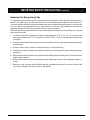
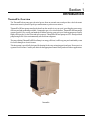
ThermalFlo
™
Heat Pump
Installation
and
User's Guide
IMPORTANT SAFETY INSTRUCTIONS
READ AND FOLLOW ALL INSTRUCTIONS
SAVE THESE INSTRUCTIONS
Customer Service
If you have questions about ordering Pentair Water Pool and Spa replacement parts, and pool
products, please use the following contact information:
Customer Service (8 A.M. to 5 P.M. — Eastern and Pacific Times)
Phone: (800) 831-7133
Fax: (800) 284-4151
Technical Support
Sanford, North Carolina (8 A.M. to 5 P.M. — Eastern Time)
Phone: (919) 566-8000
Fax: (919) 566-8920
Moorpark, California (8 A.M. to 5 P.M. — Pacific Time)
Phone: (805) 553-5000 (Ext. 5591)
Fax: (805) 553-5515
Web site
visit www.pentairpool.com or www.staritepool.com to find information about Pentair products
© 2006 Pentair Water Pool and Spa, Inc. All rights reserved.
This document is subject to change without notice.
1620 Hawkins Ave., Sanford, NC 27330 • (919) 566-8000
10951 West Los Angeles Ave., Moorpark, CA 93021 • (805) 553-5000
Trademarks and Disclaimers.The Pentair Water Pool and Spa logo, IntelliTouch and EasyTouch are registered trademarks of Pentair Water Pool
and Spa, Inc. ThermalFlo is a trademark of Pentair Water Pool and Spa, Inc. Other trademarks and trade names may be used in this document to
refer to either the entities claiming the marks and names of their products. Pentair Water Pool and Spa, Inc. disclaims any proprietary interest in
trademarks and trade names other than its own.
P/N 473426 Rev. C 10/19/06
i
Contents
Important Safety Precautions .............................................................................................. iii
Section 1: Introduction ..................................................................................................... 1
ThermalFlo Overview .............................................................................................. 1
General Features ..................................................................................................... 2
Section 2: Installation ....................................................................................................... 3
Installing the ThermalFlo .......................................................................................... 3
Materials needed for Installation .............................................................................. 3
ThermalFlo Heat Pump Dimensions ........................................................................ 4
Location ................................................................................................................... 4
Clearances .............................................................................................................. 5
Roof Run-off ............................................................................................................ 5
Equipment Pad ........................................................................................................ 5
Drainage and Condensation .................................................................................... 6
Lawn Sprinklers ....................................................................................................... 6
Anchor Clamp Installation ........................................................................................ 6
Water Connections .................................................................................................. 7
Standard Plumbing .................................................................................................. 7
Water Connections (Quick Connect)....................................................................... 8
Check Valve Installation .......................................................................................... 8
Automatic Flow Control Valve .................................................................................. 8
Multiple Unit Installation ........................................................................................... 9
Heat Pump & Heater Combination .......................................................................... 9
Multiple Heat Pump Connections ............................................................................ 10
Electrical Connections ............................................................................................. 11
General Information ................................................................................................. 11
Main Power .............................................................................................................. 11
Bonding.................................................................................................................... 11
Electrical Wiring Diagram ........................................................................................ 12
Relay Remote Controls ........................................................................................... 13
Connecting ThermalFlo to IntelliTouch or EasyTouch .............................................. 14
ThermalFlo Installation and User’s Guide
ii
Contents, continued
Section 3: Operating the ThermalFlo ............................................................................... 15
Initial Start-up Precautions ...................................................................................... 15
Operating the Controller .......................................................................................... 16
Controller Panel ....................................................................................................... 16
Indicator Lights / LEDs ............................................................................................ 17
System Indicator LEDs ........................................................................................... 17
Mode Indicator LEDs ............................................................................................... 17
Operation of Controller Buttons ............................................................................... 18
Temperature Setting ................................................................................................. 18
Mode Selection Buttons ........................................................................................... 18
Auto-Heat/Cool Mode .............................................................................................. 18
Keypad Lockout ....................................................................................................... 18
Troubleshooting the Controller ................................................................................. 19
Controller Error Codes ............................................................................................ 19
Water Pressure Switch Adjustment ......................................................................... 20
Section 4: General Maintenance ...................................................................................... 21
Water Chemistry ...................................................................................................... 21
Winterizing ............................................................................................................... 21
Spring Start-Up ....................................................................................................... 22
Inspection and Service ............................................................................................ 22
Owner Inspection .................................................................................................... 22
Professional Maintenance and Service ................................................................... 23
Section 5: Troubleshooting .............................................................................................. 25
Section 6: Replacement Parts .......................................................................................... 28
Illustrated Parts ....................................................................................................... 28
Replacement Parts List ........................................................................................... 29
ThermalFlo Installation and User’s Guide
iii
IMPORTANT SAFETY PRECAUTIONS
Important Notice:
This guide provides installation and operation instructions for the ThermalFlo HP models
of Heat Pumps. Consult Pentair Water with any questions regarding this equipment.
Attention Installer: This guide contains important information about the installation, operation and safe use of
this product. This information should be given to the owner and/or operator of this equipment after installation or left on
or near the heat pump.
Attention User: This manual contains important information that will help you in operating and maintaining this
heat pump. Please retain it for future reference.
WARNING — Before installing this product, read and follow all warning notices and instructions which are
included. Failure to follow safety warnings and instructions can result in severe injury, death,
or property damage. Call (800) 831-7133 for additional free copies of these instructions.
Codes and Standards
The ThermalFlo HP heat pump is listed by ETL as complying with the latest edition of the “UL Standard for Safety for
Heating and Cooling Equipment”, UL 1995 and CSA C22.2 No. 236.
All Pentair Water heat pumps must be installed in accordance with the local building and installation codes as per the
utility or authority having jurisdiction. All local codes take precedence over national codes. In the absence of local
codes, refer to the latest edition of the National Electric Code (NEC) in the United States and the Canadian Electric
Code (CEC) in Canada for installation.
DANGER — Risk of electrical shock or electrocution.
The electrical supply to this product must be installed by a licensed or certified electrician in
accordance with the National Electrical Code and all applicable local codes and ordinances.
Improper installation will create an electrical hazard which could result in death or serious
injury to pool or spa users, installers, or others due to electrical shock, and may also cause
damage to property. Read and follow the specific instructions inside this guide.
WARNING — To reduce the risk of injury, do not permit children to use this product unless they are closely
supervised at all times.
WARNING — For units intended for use in other than single-family dwellings, a clearly labeled emergency
switch shall be provided as part of the installation. The switch shall be readily accessible to
the occupants and shall be installed at least 5 feet [1.52 m] away, adjacent to, and within sight
of the unit.
ThermalFlo Installation and User’s Guide
iv
IMPORTANT SAFETY PRECAUTIONS (continued)
Consumer Information and Safety
The ThermalFlo series of heat pumps are designed and manufactured to provide many years of safe and reliable service
when installed, operated and maintained according to the information in this manual and the installation codes referred to
in later sections. Throughout the manual, safety warnings and cautions are identified by the “ “ symbol. Be sure to read
and comply with all of the warnings and cautions.
WARNING — The U.S. Consumer Product Safety Commission warns that elevated water temperature can be
hazardous. See below for water temperature guidelines before setting temperature.
WARNING — The following “Safety Rules for Hot Tubs” recommended by the U.S. Consumer Product Safety
Commission should be observed when using the spa.
1. Spa or hot tub water temperatures should never exceed 104° F. [40° C.]. A temperature of 100° F. [38° C.] is considered
safe for a healthy adult. Special caution is suggested for young children. Prolonged immersion in hot water can induce
hyperthermia.
2. Drinking of alcoholic beverages before or during spa or hot tub use can cause drowsiness which could lead to
unconsciousness and subsequently result in drowning.
3. Pregnant women beware! Soaking in water above 100° F. [38° C.] can cause fetal damage during the first three
months of pregnancy (resulting in the birth of a brain-damaged or deformed child). Pregnant women should stick
to the 100° F. [38° C.] maximum rule.
4. Before entering the spa or hot tub, the user should check the water temperature with an accurate thermometer. Spa
or hot tub thermostats may err in regulating water temperatures.
5. Persons with a medical history of heart disease, circulatory problems, diabetes or blood pressure problems should
obtain their physician's advice before using spas or hot tubs.
6. Persons taking medication which induce drowsiness, such as tranquilizers, antihistamines or anticoagulants should
not use spas or hot tubs.
Hyperthermia occurs when the internal temperature of the body reaches a level several degrees above normal body
temperature of 98.6° F. [37° C.]. The symptoms of hyperthermia include: drowsiness, lethargy, dizziness, fainting, and an
increase in the internal temperature of the body.
The effects of hyperthermia include:
1. Unawareness of impending danger.
2. Failure to perceive heat.
3. Failure to recognize the need to leave the spa.
4. Physical inability to exit the spa.
5. Fetal damage in pregnant women.
6. Unconsciousness resulting in danger of drowning.
ThermalFlo Installation and User’s Guide
v
IMPORTANT SAFETY PRECAUTIONS (continued)
Swimming Pool Energy Saving Tips
It is important to note that a heat pump will not heat a pool as fast as a large gas or electric pool heater. If the pool water is
allowed to cool significantly, it may take several days to return to the desired swimming temperature. For weekend use, it
is more economical to maintain the pool water temperature at or near your desired swimming temperature. If you do not plan
to use your pool for a prolonged period, then you might choose to turn the heat pump completely off or decrease the
temperature setting of the control several degrees to minimize energy consumption.
Pentair offers the following recommendations to help conserve energy and minimize the cost of operating your heat pump
without sacrificing comfort.
1. The American Red Cross recommends a maximum water temperature of 78° F. [25° C.]. Use an accurate pool
thermometer. A difference of 4° F. [2° C.] , between 78° F. and 82° F. [26° C. and 28° C.], will significantly increase energy
consumption.
2. Carefully monitor the water temperature of your pool in the summertime. You can reduce heat pump usage due to warmer
air temperatures.
3. During the winter or when on vacation for longer than a week, turn off the heat pump.
4. Find the proper setting on the heat pump temperature control and use the Keypad Lock function to discourage further
adjustments.
5. Set the pump time clock to start the pump no earlier than 6:00 AM during the pool-heating season. This is the time when
nightly heat loss balances.
6. Where possible, shelter the pool from prevailing winds with well-trimmed hedges or other landscaping, cabanas, or
fencing.
7. Always use a pool cover when practical. Besides providing a valuable safety feature, a pool cover will reduce heat
loss, conserve chemicals, and reduce the load on filter systems.
ThermalFlo Installation and User’s Guide
vi
IMPORTANT SAFETY PRECAUTIONS (continued)
General Installation Information
1. Installation and service must be performed by a qualified installer or service agency, and must conform to all
national, state, and local codes.
2. The ThermalFlo heat pump gets electrical power from an external source and provides a dual electronic
thermostat control system for pool/spa combinations or preheat convenience.
3. This heat pump is specifically designed for heating fresh water swimming pools and spas. Do not use it as a
general service heater. Consult your dealer for the appropriate Pentair Water products for these applications.
General Specifications
Installation Location Certified for use:
Outdoor use only.
Water Pipe/Heater Connection — Plastic 2” PVC (Unions included)
Flow Rate
Maximum 125 gpm [475 lpm]
Minimum 30 gpm [110 lpm]
Maximum Working Water Pressure 50 psi
Electrical Supply Voltage Requirements 1-Phase 208/230 VAC 60Hz
Requirements
1-Phase
HP 500
HP 700
HP 900
HP 1200
HP 1200R
50 A
50 A
60 A
60 A
60 A
Warranty Information
The ThermalFlo heat pump is sold with a limited factory warranty. Details are specified on the warranty card. Make all
warranty claims to an authorized Pentair Water dealer or directly to the factory. Claims must include the heat pump serial
number and model (this information can be found on the rating plate), installation date, and name of the installer. Shipping
costs are not included in the warranty coverage. The warranty does not cover damage caused by improper assembly,
installation, operation, winterizing, field modification, or failure to earth bond and properly ground the unit. Any changes to
the heat pump, evaporator, heat exchanger, wiring, or improper installation may void the warranty.
ThermalFlo Installation and User’s Guide
1
Section 1
Introduction
ThermalFlo Overview
The ThermalFlo heat pump gets electrical power from an external source and provides a dual electronic
thermostat control system for pool/spa combinations or preheat convenience.
ThermalFlo HP heat pumps transfer the heat from the outside air to your pool, providing the most energy
efficient pool and spa heating available. Compared to gas, oil, or electric heaters, ThermalFlo HP heat pumps
operate up to 80% less, saving you hundreds of dollars in energy costs each year. Our heat pumps are not only
highly efficient, they’re also clean and safe to operate. ThermalFlo HP heat pumps are ETL-listed pool heat
pumps using R410-A, the environmentally safe and clean refrigerant.
The non-polluting ThermalFlo HP Heat Pump is so energy efficient, it will keep your pool comfortably warm
for far less than gas or electric heaters.
This heat pump is specifically designed for heating fresh water swimming pools and spas. Do not use it as
a general service heater. Consult your dealer for the appropriate Pentair Water products for these applications.
ThermalFlo
ThermalFlo Installation and User’s Guide
2
General Features
•
Dual digital thermostats offer precise temperature control to maintain the desired separate water
temperatures in pool/spa combinations without overheating or wasting energy.
•
Long-life corrosion resistant composite cabinet stands up to severe climates and pool chemicals.
•
High efficiency Trane® compressor is the most energy efficient, durable, and quiet compressor available.
•
Self-diagnostic control panel monitors and troubleshoots heat pump operations to ensure safe, dependable
operation.
•
Cupronickel heat exchanger resists external corrosion and heat loss.
•
Each unit undergoes a finishing process to ensure corrosion resistance and long life.
•
Elevated base pan for positive drainage of condensation.
•
2-inch plumbing connections for easy installation.
•
Separate isolated electrical compartment prevents internal corrosion, extends heater life.
•
Compatible with IntelliTouch® and Easytouch® control systems.
•
ETL listed for safe operation.
ThermalFlo Installation and User’s Guide
3
Section 2
Installation
The following general information describes how to install the ThermalFlo heat pump.
Note: Before installing this product, read and follow all warning notices and instructions starting
on page iii.
Installing the ThermalFlo
Only a qualified service person should install the ThermalFlo heat pump.
Materials needed for Installation
The following items are needed and are to be supplied by the installer for all heat pump installations:
1. Plumbing connections (2 inch).
2. Level surface for proper drainage.
3. Suitable electrical supply line. See rating plate on unit for electrical specifications. A junction box is not
needed at the heat pump; connections are made inside of the heat pump electrical compartment. Conduit
may be attached directly to the heat pump jacket.
4. Electric cutout switch that will interrupt all power to the unit. This switch must be within line of sight of the
heat pump.
5. Watertight conduit to run the electrical supply line.
Note: We recommend installing isolation valves on the inlet and outlet water connections for ease
of serviceability.
ThermalFlo Installation and User’s Guide
4
ThermalFlo Heat Pump Dimensions
38.7"
30.7"
WATER
PRESSURE
REMOTE
THERMOSTAT
POOL
SPA
HEATING
POWER/
MODE
COOLING
AUTO-HEAT/COOL
TEMPERATURE SETTING
POOL
SPA
PRESS ANY ARROW ONCE TO
CHECK SET TEMPERATURE
A
ETL LISTED
C
US
CONFORMS TO
UL STD 1995
3044065
CERTIFIED TO
CAN/CSA STD C2 2.2 NO. 236
PART NUMBER
SERIAL NO.
CONTAINER ID
PRODUCT SPEC
LABEL
ThermalFlo™ HP
11.25"
9.25"
4.5"
6.5"
.5"
MODEL NUMBER
Dimension "A"
500
700
900
1200
1200C
1200R H/C
33.5”
33.5”
41.5”
41.5”
41.5”
41.5”
18.0"
32.0"
Figure 1.
Correct installation is required to assure safe operation. The requirements for Pentair Water heat pumps
include the following:
•
•
•
•
•
Dimensions for critical connections.
Field assembly (if required).
Appropriate site location and clearances. (See pages 4-5.)
Proper electrical wiring. (See pages vi and 11-13.)
Adequate water flow. (See page vi.)
This manual provides the information needed to meet these requirements. Review all application and installation
procedures completely before continuing the installation.
Location
CAUTION — When pool equipment is located below the pool surface, a leak from any component can cause
large scale water loss or flooding. Pentair Water Pool and Spa, Inc. cannot be responsible for such
water loss or flooding which may cause damage to the product.
Avoid placing the heat pump in locations where it can cause damage by water or condensate
leakage. If this is not possible, provide a suitable drain pan to catch and divert any leakage.
ThermalFlo Installation and User’s Guide
5
Clearances
All criteria given in the following sections reflect minimum clearances. However, each installation must also be
evaluated, taking into account the prevailing local conditions such as proximity and height of walls, and proximity
to public access areas.
The heat pump must be placed to provide clearances on all sides for maintenance and inspection.
1. At least 24 in. [61cm] access must be available in the front and 12 in. [30 cm] on all the other sides of the
heat pump for service, see Figure 2.
2. If the heat pump is to be installed under a cover or under a vertical overhang, the unit must have a minimum
of four (4) feet [1.22 m] clearance from the top of the heat pump.
3. Install a minimum of five (5) feet [1.52 m] from the inside wall of the pool or spa unless the heat pump is
separated from the pool or spa by a five (5) foot high solid fence or other permanent barrier. Canadian
installations require a minimum of three (3) meters from pool water.
DO NOT ALLOW ROOF
RUN-OFF TO FLOW INTO
THE UNIT.
OPEN
25˚
MAXIMIM
ROOF PITCH
WITHOUT A GUTTER
OVER HANG
AIR FLOW OUT
48"
EVAPORATOR
COILS
SERVICE
ACCESS
24" to 36"
12"
AIR
FLOW
IN
12"
3"
12"
Figure 2.
SLAB
Roof Run-off
Make sure the heat pump is not located where large amounts of water may run-off from a roof into the unit.
Sharp sloping roofs without gutters will allow massive amounts of rain water, mixed with debris from the
roof to be forced through the unit, see Figure 2. A gutter or down spout may be needed to protect the
heat pump.
Equipment Pad
Place the heat pump on a flat slightly pitched surface, such as a concrete or fabricated slab (pad). This allows
proper drainage of condensation and rain water from the base of the unit. If possible, the pad should be placed
at the same level or slightly higher than the filter system equipment pad.
NOTE: Ensure that the pad is pitched not more than 1/4 in. per foot toward the compressor end (front)
of the heat pump. Pitch slab from back to front 1/4 in. per foot maximum and level from side to side.
ThermalFlo Installation and User’s Guide
6
Drainage and Condensation
Condensation will occur from the evaporator coil while the unit is running and drain at a steady rate, usually three
to five gallons per hour, depending upon ambient air temperature and humidity. The more humid the ambient
conditions, the more condensation will be produced. The bottom of the unit acts as a tray to catch rainwater and
condensation. Keep the drain holes, located on the bottom pan of the base of the unit, clear of debris.
Lawn Sprinklers
Make sure there are absolutely no sprinkler heads near the heater that will in
any way spray on or into the heater. Sprinkler damage is not covered under
the warranty agreement.
Make sure that they’re a sufficient distance away so that normal winds will not
carry the mist to the heater. If your filtering system area has plants that need water,
use a trickle type irrigation sprinkler instead of the broadcast type.
NO SPRINKLERS
WITHIN A
6 FT. RANGE
The heater is designed to handle the wettest weather conditions that are typical of
Figure 3.
rain and humidity, etc. Sprinkler heads force high pressure water into the unit from
the side at an odd angle. Most sprinkler systems are connected to a well system. Most well water is high in
minerals, sulphur and other aggressive contaminates. These contaminates will leave a build up on the evaporator
coils and electronics causing corrosion and hamper the efficiency. If you are located within 15 miles of the
coast, salt may also be in the well water.
Anchor Clamp(s) Installation
In Florida, building codes require that the heat pump be anchored to the equipment pad or platform to
withstand high wind pressures created during hurricanes.
This heat pump is provided with anchor clamps designed to hold the unit to the equipment pad in high wind
conditions. Installation of the anchor clamps are recommended in all installations and are required in Florida
(See Florida Building Code 301.13).
To install the anchor clamps:
1. Be sure that the heat pump is in its permanent location on the equipment pad.
2. Remove the anchor clamps from the installation and instruction package.
Note: Bolts and bolt anchors are not included with the heat pump.
The installer must provide 1/4” x 1-3/8” stainless steel anchor bolts
and the appropriate size concrete anchor to mount the clamp to the
equipment pad.
3. Place the clamps at the base of the heat pump in the locations
indicated in Figure 4, (2 in. undercut [notched area] on either
side).
4. Fit the hook of each clamp over the lip on the base panel of the
heat pump. The hook should fit between the lip of the base panel
and the evaporator coil guard, see Figure 5.
HEAT PUMP
CLAMPS
HEAT PUMP
CLAMPS
5. Mark the position of the hole in each clamp on the equipment pad.
Figure 4.
ThermalFlo Installation and User’s Guide
7
Anchor Clamp(s) Installation, continued
6. Drill a hole in the cement using a masonry drill bit, with a
diameter as determined by the concrete anchor, at each of the
marks on the equipment pad. The hole should be approximately
1½ in. deep.
7. Insert a bolt anchor into each of the holes. Be sure the anchors
are set completely into the holes
8. Position the anchor clamps so that the holes in the clamps are
over the bolt anchors. Be sure that the clamp hooks are over the
lip of the heat pump base, see Figure 5.
AIR COIL GUARD
AIR
COIL
1-3/8" HEX BOLT
(installer provided)
HEAT PUMP
ANCHOR CLAMP
HEAT PUMP
BASE
BOLT ANCHOR
(installer provided)
CONCRETE
EQUIPMENT PAD
9. Insert an anchor bolt through each clamp into the anchor and
tighten to secure the clamp and heat pump to the equipment pad.
Figure 5.
Water Connections
Plumbing layout
See Figure 6, illustrating the standard plumbing layout with a single heat pump unit. Following the diagram from
right to left, the plumbing sequence is as follows:
Pool > Skimmer and Main Drain > Pool Pump > Filter > Heat Pump > Check Valve > Chemical Loop > Chlorinator > Pool
NOTE: For normal installations, do not install a shut-off valve or any kind of variable restriction in
the water piping between the heat pump outlet and the pool/spa.
The heat pump must be protected from back-siphoning of water. If there is any chance of back-siphoning,
provide a check valve between the pool and the heat pump outlet. Arrangement of pool system components
other than as illustrated in Figure 6. and the following diagrams can affect the operation of the heat pump’s
water pressure switch. Location of the heat pump above or below the pool water surface can also affect
operation of the switch. In general, the pressure switch can be adjusted to accommodate this effect if the heat
pump water connections are no more than six (6) feet below the pool water surface or no more than fifteen 15
feet above it. See instructions for pressure switch adjustment (page 20) in the heat pump start-up section of this
manual for more information. If the heat pump is installed outside of this range, an external pressure switch may
need to be installed in the plumbing upstream of the heat pump. Call the Pentair Water Heat Pump Technical
Service department at (800) 831-7133 for details.
Be advised that when pool equipment is located below the pool surface a leak can result in large-scale water
loss or flooding. Pentair cannot be responsible for such water loss or flooding or the damage caused by either
occurrence.
POOL HEATER
FILTER
CHEMICAL LOOP
CHEMICAL FEEDER
2 LB.
CHEMICAL RESISTANT
CHECK VALVE
POOL PUMP
FROM POOL OR SPA
MANUAL BYPASS VALVE
TO POOL OR SPA
Figure 6. Standard Plumbing Layout
ThermalFlo Installation and User’s Guide
8
Water Connections at the Heat Pump
Two inch Quick Connect fittings have been installed on the water inlet
and outlet connections, see Figure 7. Filtered cool water is plumbed
to the inlet, located on the right side of the heat pump front panel.
Heated water flows through the outlet, located on the left side of the
heat pump front.
Water
Inlet Union
Plastic piping (PVC Schedule 40) should be connected to the heat
pump. The unions, provided with the unit, accept 2 in. PVC pipe.
CAUTION — Make sure that flow requirements and pool water
turnover rates can be maintained with the installation of
additional heat pumps and plumbing restrictions.
Water
Outlet Union
Figure 7.
Check Valve Installation
The heat pump must be protected from back-siphoning of water. If there is any chance of back-siphoning,
provide a check valve between the pool and the heat pump outlet.
CAUTION — The chlorinator placement, water balance, and where chemicals are added, are very important
aspects of the installation. Failure to protect the heat pump unit from chemical damage is not
covered under the warranty.
When an automatic chemical feeder is installed in the plumbing, it must be installed downstream of the
heat pump. A check valve must be installed between the heat pump and the chemical feeder to prevent
back-siphoning of chemically saturated water into the heat pump where it will damage the components.
Automatic Flow Control Valve
The inlet/outlet header of the ThermalFlo HP heat pump comes equipped with an internal automatic flow
control valve. The automatic flow control valve maintains the proper flow through the heat pump at rates up to
125 gpm (475 lpm). If the filter system flow rate is higher than 125 gpm (475 lpm), install a manual bypass
valve, see Figure 6 on page 7.
NOTE: Be advised that if your circulation pump is over 2 HP or if the total flow exceeds 125 gpm, you
will have to add an external bypass valve. Excess water flow will damage the heat exchanger.
ThermalFlo Installation and User’s Guide
9
Multiple Unit Installation
Heat Pump, Heater and/or Solar Combination
In certain regions of the country it may be more economical to run a heat pump during the warmer months and
a gas heater during the cooler months. In some situations it may be desirable to run the heat pump in the
“Chiller” mode, if so equipped, during the hottest portion of the year and a heater during the cooler months.
The Pentair Water heat pump may be used in conjunction with a gas or electric heater or any combination of
heat sources including solar. All heat sources must be plumbed in series to work correctly and efficiently.
A recommended plumbing layout for a heat pump / heater / solar combination heating system for a pool / spa
combination is shown in Figure 8. Your system may not contain all of these components, but the basic plumbing
will apply by eliminating the component in the illustration that is not a part of your system.
HEATER
POOL
RETURN
HEAT PUMP
VALVE
SPA
MAKE-UP
POOL
INTAKE
VALVE
SPA
RETURN
TO SOLAR
FILTER
POOL
DRA
SPA
INTAKE
S
DRAIN
Figure 8.
ThermalFlo Installation and User’s Guide
10
Multiple Heat Pump Connections
All plumbing on multiple heat pump installations must be done in parallel see Figures 9 and 10. An equal flow
of water to each heat pump is important for optimum operation.
NOTE: It may be necessary to adjust water pressure switch if a unit is installed below the water
level. See page 20 for details on when and how to adjust the pressure switch.
Each heat pump allows a maximum flow rate of 125 gpm and requires a minimum of 30 gpm.
24 inches min. clearance around evap.
24"
Check Valves are
optional on heater inlets
but will help system
balancing
2" PVC Pipe
Extend12" past
end heater inlet
for hydraulic
balancing
Extend12" past
end heater inlet
for hydraulic
balancing
OPTIONAL
2" Check Valve Bypass
Flow Meter
Flow Meter
To Pool
Pool Pump
Figure 9.
Minimum
2" PVC Pipe
Two Heat Pump Plumbing Layout
24 inches min. clearance around evap.
24"
2" PVC Pipe
Extend12" past
end heater inlet
for hydraulic
balancing
2" PVC
Pipe
3" PVC Pipe
Flow Meter
2" PVC
Pipe
Check Valves are
optional on heater inlets
but will help for system
balancing
2" PVC
Pipe
Extend12" past
end heater inlet
for hydraulic
balancing
3" PVC Pipe
Flow Meter
3" Ball Valve Bypass
To Pool
Pool Pump
Minimum
3" PVC Pipe
Figure 10. Four Heat Pump Plumbing Layout
ThermalFlo Installation and User’s Guide
11
Electrical Connections
WARNING —Risk of electrical shock or electrocution.
This heat pump contains wiring that carries high voltage. Contact with these wires could result in death
or serious injury to pool or spa users, installers, or others due to electrical shock, and may also cause
damage to property. Always disconnect power circuit before connecting the heat pump.
CAUTION — Label all wires prior to disconnection when servicing controls. Wiring errors can cause improper and
dangerous operation. Verify proper operation after servicing.
General Information
Wiring connections must be made exactly as shown in the wiring diagram found on the inside of the heat pump
access panel, see Figure 11 on page 12. The heat pump must include a definite means of grounding and
bonding. There is a ground lug inside the heat pump electrical compartment and a bonding lug on the left side
of the heat pump.
Main Power
Electrical wiring to the heat pump must be in accordance with the latest edition of the National Electric Code
(NEC), ANSI/National Fire Protection Association (NFPA) 70 in the United States, and in Canada, the
Canadian Electrical Code (CEC) C22.1, unless local code requirements indicate otherwise. All wiring must be
done by a certified electrician.
The following is the procedure to wire the ThermalFlo HP to the electrical source:
Be sure the power to the circuit for the heat pump is turned off.
1. Remove the front left panel of the heat pump cabinet, (you do not need to remove the torque head
screw at the top left corner).
2. Remove the service panel to the heat pump electrical compartment. (front left corner of unit)
3. Electrical supply lines must be run through watertight conduit. Run the wires and conduit from the power
source and connect them to the conduit connection on the left side of the heat pump.
4. Connect the power leads to the terminals on the main contactor as shown in the wiring diagram.
5. Verify that all other contactor wires are secure, they may have loosened during shipment.
6. Connect the ground wire to the ground lug provided on the bottom of the electrical compartment.
7. Replace the service panel and reinstall screws to hold it in place.
8. Replace the front left panel.
9. Connect a copper bonding wire (8 AWG) to the bonding lug on the left side of the heat pump.
Bonding
CAUTION — This heater must be connected to a bonding grid with a solid copper wire not smaller in diameter
than 8 ga.
The National Electrical Code and most other codes require that all metallic components of a pool structure,
including reinforcing steel, metal fittings, and above ground equipment be bonded together with a solid copper
conductor not smaller than 8 AWG. The heat pump, along with pumps and other pool equipment must be
connected to this bonding grid. A bonding lug is provided on the left side of the heat pump to ensure this
requirement is met.
ThermalFlo Installation and User’s Guide
12
Wiring Diagram
460812, 460813, 460814, 460815, 460822, 460804
Heat Pump Control Board
PO
OL
SP
A
REMOTE
CO
M
10K
Thermistor
SO
SO
R
LE
NO
ID
AU
24 VAC
BLUE
TBL
YELLOW
WHITE
WHITE
BLACK
BLACK
RED
Water Pres Sw
Hi Ref Pres Sw
Switch factory set to H
for 460812, 460813,
460814, 460815, set to
C for 460804, and set to
AU for 460822
(on back of circuit board)
PR
ES
C
FA
N
CO
M
LO
PR W
ES
RE
S
H
HI
P
W
AT
E
R
FL
OW
TEMPERATURE
THERMISTER
RED
Lo Ref Pres Sw
1
2
3
4
5
6
7
8
Optional
Reversing Valve on
460822
TBR
BLUE
WHITE
YELLOW
PURPLE
WHITE
WHITE
BLACK
BLACK
1
2
3
4
5
6
WHITE
PURPLE
BLACK
BLACK
RED
RED
Transformer
COM
YELLOW
ORANGE
Capacitor
24
VAC
50 mf
208 VAC
7.5 mf
BLUE
BLACK
BROWN
TAN
PINK
PURPLE
240 VAC
RED
BLACK
BROWN
RED
BROWN
WHITE
BLACK
Green
Red
Compressor
BLACK
Fan
Relay
BROWN
BLUE
Contactor
PURPLE
COM
NO
NC
BLACK
PURPLE
GREEN
C
S
R
RED
Fan
Incoming 220 VAC
Power Connection
Figure 11.
ThermalFlo Installation and User’s Guide
473073
13
Relay Remote Controls
Electrical wiring must be in accordance with the latest edition of the NEC (NFPA 70) in the United States and
CEC (CSA 22.1) in Canada, unless local code requirements indicate otherwise. To connect remote control
equipment to the heat pump, perform the following steps:
1. Turn off the power to both the remote pool/spa control system and the heat pump.
2. Remove the front left panel of the heat pump cabinet, (you do not need to remove the torque head
screw at the top left corner).
3. Remove the electrical service panel to the heat pump. Remove the 4 bezel retaining screws from above the
electrical compartment and rotate the bezel downward. This will allow you to access the Remote terminals
on the back of the ThermalFlo HP control board for the remote control installation.
4. Run the wires from the pool/spa remote control system into the upper electrical compartment.
5. Connect the wiring from the pool/spa remote control system to the heat pump remote control terminals using
¼ in. “Fast On” connectors as shown in the figure below.
6. Rotate the bezel back upwards into position and reinstall the 4 retaining screws.
7. Replace the electrical service panel.
8. Replace the front left panel.
9. Restore power to the heat pump and the pool/spa remote control system.
REMOTE
SPA
POOL
PO
OL
CO
M
SP
A
Heat Pump Control Board
(3) Fast-On
Connectors
ID
O
LE
N
ES
SO
CO
24 VAC
SO
PR
AU
M
C
FA
N
H
LO
PR W
ES
PR
ES
HI
W
AT
ER
FL
OW
R
TEMPERATURE
THERMISTER
Figure 12.
ThermalFlo Installation and User’s Guide
14
Connecting the ThermalFlo to the IntelliTouch® or EasyTouch® Load Center
To connect the ThermalFlo cable to the Personality Board in the IntelliTouch or EasyTouch Load Center:
1. Turn off the main system power before making any connections.
2. Unlatch the front door spring latche(s), and open the front door of the IntelliTouch or EasyTouch
Load Center.
3. Loosen the two retaining screws from the top of the control panel and lower the control panel down
to access the Personality Board.
4. Run a UL approved conductor cable from the ThermalFlo to the Load Center.
5. Route the cable up through the low voltage raceway located on the left of the Load Center to the
Personality Board, see Figure 13.
6. Insert the ThermalFlo cable plug onto the gas heater terminal connector, located on the left side of
the Personality Board.
7. If the heat pump is used in conjunction with a gas heater, use a 520403 Dual Heater Relay Kit. Plug
the heat pump relay connector onto the SOLAR Terminal on the top center of the Personality Board.
Follow the Dual Heater Relay Kit instructions for further set-up details.
8. Lift the control panel up into position and secure with the two screws.
9. Connect the cable from the IntelliTouch or EasyTouch Load Center to the heat pump remote control
terminals using ¼ in. “Fast-On” Spade connectors, see Figure 12 on the previous page.
TEMP. SENSORS HAVE NO POLARITY.
RED/BLK WIRES ARE INTERCHANGEABLE.
BLK
GRN
YEL
RED
Figure 13.
ThermalFlo Installation and User’s Guide
15
Section 3
Operating ThermalFlo
This section describes how to operate the ThermalFlo heat pump.
Initial Start-up Precautions
CAUTION — Do not use this heat pump if any part has been under water. Immediately call a qualified service
technician to inspect the heater and replace any part of the control system which has been under
water.
CAUTION — Keep all objects off the top of the heat pump. Blocking air flow could damage the unit and may void
the warranty.
ATTENTION
After starting the ThermalFlo heat pump, please note that there is a 5 minute delay before the compressor begins operation.
The heat pump display will show the remaining delay time in minutes and hundredths of a minute.
Be sure that there is water in the pool and that the surface level is above the skimmer or other inlets of the pool’s filter system.
The pool pump must be on and water flowing through the heat pump for it to operate.
With any new pool or spa installation, operate the filter pump with the heat pump off long enough to completely clean the
water. This will remove any installation residue from the water. Clean the filter at the end of this operation before starting the
heat pump. When raising the temperature of a cold pool, program the time clock to run the pump continuously. This lets the
filter system and heat pump operate continuously until the water reaches the temperature setting on the temperature control.
When that happens, the heat pump will automatically shut off, but the filter pump will keep running.
Figure 14.
ThermalFlo Installation and User’s Guide
16
Operating the Controller
An advanced microprocessor based controller that provides a sophisticated yet simple interface to operate
your heat pump for maximum efficiency and enjoyment of your pool, controls the ThermalFlo HP heat pump.
It will control incoming water temperature between a minimum of 60º and a maximum of 104º F. The controller
also serves as system status indicator, using LED lights and error codes, see Figure 15.
During normal operation, the controller displays the temperature of the water returning to the heat pump.
Changing the desired pool or spa temperature is easily done by simply pressing the appropriate “Up” or
“Down” arrow until the display reads the desired temperature. The display returns to current water temperature
when setpoint adjustment is complete.
To display the current setpoint, simply touch the appropriate “Up” or “Down” arrow. The display will momentarily
display the current setpoint. Note that the POOL LED must be on to display or adjust the pool setpoint and
the SPA LED must be on to display or adjust the spa setpoint.
WATER
PRESSURE
REMOTE
THERMOSTAT
POOL
SPA
HEATING
COOLING
AUTO- HEAT/COOL
ERROR CODES:
E01 - Low Refrigerant Pressure
E02 - High Refrigerant Pressure
E03 - Remote Error
E04 - Switch Fault
Err - Thermistor Error
LO - Water Temperature Low
HI - Water Temperature High
POWER/
MODE
TEMPERATURE SETTING
POOL
SPA
PRESS ANY ARROW ONCE TO
CHECK SET TEMPERATURE
Figure 15.
Main Control Panel
ThermalFlo Installation and User’s Guide
17
Indicator Lights / LEDs
Nine lights can be seen from the front of the control panel. Five are system indicators and four are mode
indicators. These lights help the operator and service person understand the operation of the heat pump and
aid in troubleshooting problems.
System Indicator LEDs
1. WATER PRESSURE: On when in REMOTE, POOL or SPA mode and sufficient water is flowing
through the heat pump.
2. THERMOSTAT: On when the controller is calling for heating or cooling.
3. HEATING: On when heat pump is configured for heating.
4. COOLING: On when heat pump is configured for cooling.
5. AUTO – HEAT COOL: On when switch SW1, located on the back of the controller board, is in the
AU position. This indicates that the heat pump can operate as a heater and a cooler.
(Only used on Model HP 1200R.)
Mode Indicator LEDs
1. REMOTE LED: On when the controller is being controlled by the three remote terminals on the back
of the control board, (SPA, COM and POOL). When using REMOTE mode, the local setpoints should
be outside the temperature band that the remote device will be controlling at. (Set the pool and spa
temperature setpoints to the maximum settings — 104° F. for heat, 60° F. for cool).
2. POOL LED: On when heat pump is maintaining water temperature at the POOL setpoint.
3. SPA LED: On when heat pump is maintaining water temperature at the SPA setpoint.
4. POWER/MODE LED: On when the heat pump is OFF and there is power to the unit.
ThermalFlo Installation and User’s Guide
18
Operation
Temperature Setting
The heat pump comes factory set at 78º F. for POOL mode and 100º F. for SPA mode. Start by selecting
either the POOL or SPA mode to turn the heater on, then using the “Up” and “Down” arrows, you can set the
thermostat anywhere between a minimum temperature of 60º F. and a maximum of 104º F.
Mode Selection Buttons
1. REMOTE button: Places the heat pump in REMOTE mode whereby its starting and stopping is controlled
by relays in a remote device connected to the remote terminals on the back of the control board.
2. POOL button: Places the heat pump in POOL mode which causes it to start and stop as necessary to
maintain water temperature at the pool setpoint.
3. SPA button: Places the heat pump in SPA mode which causes it to start and stop as necessary to maintain
water temperature at the spa setpoint.
4. POWER/MODE button: On the heat only and cool only heat pump models, the POWER/MODE button
turns off the heat pump, (Models HP 500, HP 700, HP 900, HP 1200 and HP 1200C). On auto heat and
cool units, (Model HP 1200R), the POWER/MODE button switches the heat pump between OFF,
HEATING, COOLING and AUTO-HEATING/COOL configurations.
Auto-Heat/Cool Mode (Applicable to Model HP 1200R ThermalFlo heat pumps only)
The Model HP 1200R ThermalFlo heat pump has the ability to operate as a heater, cooler and to automatically
switch back and forth between heating and cooling. This is controlled by the POWER/MODE button.
The POWER/MODE button causes the heat pump to switch from HEATING to COOLING to
AUTO-HEAT/COOL to Off.
Keypad Lockout
To lockout the control panel in any operating mode, press and hold the REMOTE and SPA down buttons
simultaneously. All control panel buttons will be disabled. If any button is pressed, the display will indicate Loc
for a few seconds. To unlock the keypad, press and hold the REMOTE and SPA down buttons simultaneously
again.
ThermalFlo Installation and User’s Guide
19
Troubleshooting
The control panel contains a three digit LED display. These LEDs display temperatures, lock out status and
error codes. The error codes are listed below:
CODE
NAME
CAUSE
E01
Low Refrigerant Pressure
Low refrigerant pressure switch open.
E02
High Refrigerant Pressure
High refrigerant pressure switch open.
E03
Remote Error
Pool and Spa remote inputs on simultaneously.
E04
Switch Fault
SW1 position indeterminate.
Err
Thermistor Error
Temperature sensor reading open or shorted.
LO
Water Temperature Low
Water temperature below 45° F.
HI
Water Temperature High
Water temperature above 106° F.
ThermalFlo Installation and User’s Guide
20
Water Pressure Switch Adjustment
CAUTION — The water pressure switch should be adjusted to turn the heater off when the pump is off. Setting the
switch to close at too low of a flow can damage the appliance. Adjust the switch to turn the heater off,
not on.
The pressure switch is preset at the factory for activation at 1.5 psi [10 kPa]. This factory setting works for all
basic installations as shown previously on pages 7, 9-10 in this manual. Only adjust the water pressure switch if
the heat pump does not operate when the proper flow is applied to unit or if the heat pump does not shut off
when the filter pump is off. Occasionally, unusual plumbing configurations or necessary restrictions in the plumbing
may cause pressure sensing problems. In these rare situations, the plumbing system configuration may require
adjustment of the water pressure switch.
Adjustment of the pressure switch may be necessary if any part of the filter system piping is 3 feet [0.91 m] or
more above the top of the heat pump jacket.
Do not adjust the pressure switch if the heat pump is installed more than 15 feet [4.57 m] above or
6 feet [1.83 m] below the pool surface. Consult your local Pentair Water representative for recommendations.
On some installations, the piping from the heat pump to the pool is very short. The back pressure could be too low
to trigger the pressure switch. If this happens, it may be necessary to install a directional fitting or elbows where
the return line enters the pool. This will increase back pressure enough for the heat pump to operate properly.
If this configuration is necessary, be sure to check that the system flow is above the minimum requirement of
30 gpm after the direction fitting or elbow has been installed.
Make sure the pool filter is clean before making any pressure switch adjustment: A dirty filter will restrict the
water flow and the pressure switch cannot be adjusted properly.
To adjust the pressure switch:
1. Be sure that all valves in the system are set to allow water flow through the heat pump. Start the filter pump.
2. Set the heat pump control to call for heat. Set the On/Mode switch on the heat pump control to the “ON”
position.
3. If the heat pump control water pressure indicator LED is Off, then the flow in the system may be below the
minimum flow of 30 gpm needed for the safe operation of the heat pump. Investigate and correct any flow
problems before adjusting the water pressure switch. If the flow is above 30 gpm and the light is Off, adjustment
is required.
4. Remove the heat pump’s left front panel and remove remaining right front panel. The water pressure switch
is located in the water plumbing in the lower right corner of the heat pump.
5. Slowly rotate the adjustment wheel on the water pressure switch in a counterclockwise direction until the
“Water Pressure Indicator” LED is On. Remember that there is a time delay before the heat pump
compressor will start.
6. Once the heat pump is running, turn off the filter pump. The heat pump should turn off immediately.
7. If the heat pump continues to operate when the filter pump is off, turn the adjustment wheel on the water
pressure switch in a clockwise direction until “Water Pressure Indicator” LED is Off and the heat pump
stops.
8. Check the setting of the water pressure switch by starting and stopping the filter pump and checking the control
display and operation of the heater between each flow change.
9. If the water pressure switch cannot be adjusted to accommodate the conditions listed above, an external flow
switch must be added to the plumbing system to ensure that the heat pump will not operate without the proper
flow through the heat exchanger.
ThermalFlo Installation and User’s Guide
21
Section 4
General Maintenance
Water Chemistry
Proper chemical balances are necessary for sanitary bathing conditions as well as ensuring your heat pump’s
long life. Be sure to keep your chemical and mineral concentration levels within the values indicated in Table 1.
Failure to maintain proper water chemistry may void the warranty.
Test
Recommended Level
Free Chlorine or
1.0 to 3.0 ppm (3.0 to 5.0 spa)
Bromine
2.0 to 4.0 ppm (3.0 to 5.0 spa)
pH
7.4 to 7.6
Total Alkalinity (TA)
80 to 120 ppm
Calcium Hardness (CH)
200 to 400 ppm
Cyanuric Acid
30 to 50 ppm
Total Dissolved Solids (TDS)
Less than 2000 ppm
Copper
0 ppm
* Concentration levels taken from "Basic Pool and Spa Technology"
published by NSPI (National Spa and Pool Institute).
Table 1. Optimal Water Chemistry Ranges
NOTE: For spas, it is also necessary to perform water changes in addition to chemical treatment. It is
recommended to change the spa water every 60 days for light usage and every 30 days if usage is heavy.
Winterizing
CAUTION — Failure to winterize could cause damage to the heat pump and will void the warranty.
In areas where freezing temperatures occur, you should
protect your pump, filter, and heat pump from the elements.
Perform the following steps to completely drain the heat
pump, see Figure 16.
1. Turn off the electrical power to the heat pump at the
main breaker panel.
2. Shut off the water supply to the heat pump.
3. Disconnect the water inlet and outlet unions located on
the lower front panel of the heat pump.
Water
Inlet Union
4. Cover only the top of the heat pump to prevent debris
from falling into the unit. Do not wrap the sides of the
heat pump with any plastic or other material that will
retain heat or moisture inside the unit.
Water
Outlet Union
Figure 16.
ThermalFlo Installation and User’s Guide
22
Spring Start-Up
If your heat pump has been winterized, perform the following steps when starting the system in the Spring:
1. Uncover the heat pump and inspect the top and sides for any debris or structural problems.
2. Connect the water inlet and outlet unions located on the lower front panel of the heat pump.
3. Turn on the filter pump to supply water to the heat pump. Open the filter air bleeder and circulate water
through the system long enough to bleed all the air out of the pool system. Check for leaks in and around
the heat pump.
4. Turn on the electrical power to the heat pump at the main breaker panel.
Inspection and Service
Pentair Water Heat Pumps are designed and constructed to provide long performance life when installed and
operated properly under normal conditions. Periodic inspections are important to keep your heat pump running
safely and efficiently through the years.
Owner Inspection
Pentair Water recommends that you inspect your heat pump on a continual basis and especially after abnormal
weather conditions. The following basic guidelines are suggested for your inspection:
1. Make sure the front of the unit is accessible for future service.
2. Keep the top and surrounding areas of the heat pump clear of all debris.
3. Keep all plants and shrubs trimmed and away from the heat pump.
4. Keep lawn sprinkler heads from spraying on the heat pump to prevent corrosion and damage. Use a deflector
if needed.
5. If the unit is installed under a very sharp roof pitch or under a roof without a gutter, a gutter or diverter should
be fitted to prevent excessive water from pouring down into the unit.
6. Do not use this heat pump if any part has been under water. Immediately call a qualified professional
technician to inspect the heat pump and replace any part of the control system which has been submerged.
The heat pump will produce condensation (water) while in operation. The heat pump base is designed to allow
the condensation to exit through the bottom drain port when the unit is running. The condensation will increase
as the outdoor air humidity level increases. Check the following at regular intervals to ensure proper condensate
drainage:
1. Visually inspect and clear the bottom drain ports of any debris that could clog the ports.
2. Keep the top air flow discharge and air flow intake area clear of debris so the air flow though the heat pump
is not restricted. The cooler discharge air from the top should not accumulate and be drawn into the side air
intake coils.
3. Ensure that condensate run-off is properly directed away from the equipment pad to keep it from
undermining the pad.
4. Ensure that condensate water does not puddle inside the heat pump.
During normal operation, the heat pump produces three to five gallons of condensate per hour. If condensate
drainage is above this range during operation or if water continues to drain from the base when the heat pump
is not in operation for more than an hour, a leak in the internal plumbing may have occurred. Call a qualified
heat pump technician to investigate the problem.
ThermalFlo Installation and User’s Guide
23
Professional Maintenance and Service
The Pentair ThermalFlo Heat Pump is one of the most efficient ways to heat a pool or spa. The heat pump
transfers heat from the outside air to the pool or spa water by means of an internal heat exchanger.
When the fan is turned on, warm air is drawn through the R410A refrigerant charged air coil, turning the cold
liquid refrigerant to a warm gas. The gas then flows through the reciprocating compressor, which increases the
pressure and refrigerant temperature. The hot refrigerant gas enters the water to gas heat exchanger where the
water is heated and returned to the pool. During this heat exchange process the refrigerant is cooled and
returned to the air coil and the cycle repeats.
NOTE: The maximum heat output and efficiency of a heat pump is dependent upon the quality and performance
of the major components used. As equally important are the environmental conditions (for example, air
temperature, humidity, water temperature, and wind).
COLD
AIR OUT
FAN
WATER
INLET
(Cold)
WARM
AIR IN
EVAPORATOR
COIL
Figure 16.
WATER
OUTLET
(Warm)
Typical Heating Cycle
ThermalFlo Installation and User’s Guide
24
ThermalFlo Installation and User’s Guide
25
Section 5
Troubleshooting
Use the following troubleshooting information to resolve possible problems with your ThermalFlo heat pump.
WARNING — RISK OF ELECTRICAL SHOCK OR ELECTROCUTION.
Improperly installation will create an electrical hazard which could result in death or serious injury
to pool users, installers, or others due to electrical shock, and may also cause damage to property.
Do NOT attempt any internal adjustments inside the heater.
1. Keep your hands and hair clear of the fan blades to avoid injury.
2. If you are not familiar with your pool filtering system and heater:
a. Do NOT attempt to adjust or service without consulting your dealer, professional pool or air
conditioning contractor.
b. Read the entire Installation & User’s Guide before attempting to use, service or adjust the
heater or pool filtering system. The water pressure switch should be adjusted to turn the
heater off when the pump is off. Setting the switch to close at too low of a flow can damage the
appliance. Adjust the switch to turn the heater off, not on.
Note: Turn off power to unit prior to attempting service or repair. Problems and Corrective Action
Problem
Possible Cause
Corrective Action
All control lights off.
Unit will not start.
No power supply to heater. Tripped breaker or
blown fuse. Control failure.
Reset breaker. Replace fuse. Call dealer for advise.
Call factory for advise.
Remote, Pool or Spa light ON.
Water Pressure light OFF.
Thermostat light ON.
Unit will not start.
Low water flow through heater. Dirty or worn
filters or clogged lint traps. Clogged filter pump
impeller. Improper plumbing valve settings.
Suction leak allowing air into the water flow.
Internal water pressure switch failure.
Clean entire filtering system and or replace filter
element. Inspect & clean pump impeller. Adjust
plumbing valves. Repair suction air leaks, grease
pump lid o-ring. Replace filter. Replace water pressure
switch. Check water pressure switch adjustment.
Water Temperature not hot enough.
Remote, Pool or Spa light ON.
Water Pressure light ON.
Thermostat light OFF.
Unit will not run.
Thermostat is not set higher than the pool/spa
water temperature. The water temperature has
reached the current setting. The thermostat is
malfunctioning. The pool/spa select switch is not
in the correct mode.
Increase set point temperature. Maximum water
temperature is 104° F. Call your dealer for advise.
Call the factory for advise.
Remote, Pool or Spa light ON.
Water Pressure light ON.
Thermostat light ON.
Unit will not start.
Outside air temperature below operating range
of 45° F. Discharge air flow is restricted.
Discharge air is accumulating and being drawn
back through the outer air coil. The fan is
obstructed, low air flow. Large amounts of roof
run off water restricting fan blade rotation.
Sprinklers spraying on the outer air coil during
cooler temperatures. Outer air coil clogged with
debris. Plants too close to heater, blocking air
flow. Low refrigerant pressure caused by a
Freon™ leak. Possible malfunctioning of the
internal low refrigerant pressure switch.
Do not try to operate the heater when the outside air
temperature drops below 50° F. Make sure heater is
installed with the required placement clearances for
air flow and roof clearance. Do not install indoors.
Make sure that your sprinklers do not spray on the
heater in any way what so ever. If ice forms on the
outer coil, shut the heater off and allow ice to thaw.
You may use water at low pressure to thaw ice build
up on the outer coil, shut the heater off when doing
so. Call the factory for advice.
OR
Unit is forming ice or frost on the
outer air coil, usually at the bottom.
ThermalFlo Installation and User’s Guide
26
Problem
Possible Cause
Corrective Action
Remote, Pool or Spa light ON.
Water Pressure light ON.
Thermostat light OFF.
EO1 Error
Unit will not run.
Low or restricted water flow through heater. Dirty
or worn filters or clogged lint traps. Clogged
filter pump impeller. Improper plumbing valve
settings. Suction leak allowing air into the water
flow. Low water flow when switched to spa mode.
Unit is plumbed backwards. Heat exchanger
clogged with debris. Internal bypass valve
damaged or clogged with debris. Refrigerant
system malfunction.
Clean entire filtering system and or replace filter
element. Inspect & clean pump impeller. Adjust all
plumbing valves. Repair suction air leaks, grease
pump lid o-ring. Replace filter. Wrong filter pump pipe
size. Automatic pool vacuum causing restriction.
Recharge refrigerant if required.
Call your dealer for advise. Call the factory for advise.
Remote, Pool or Spa light ON.
Water Pressure light ON.
Thermostat light ON.
Unit is cycling on & off.
Low or restricted water flow through heater. Dirty
or worn filters or clogged lint traps. Clogged
filter pump impeller. Improper plumbing valve
settings. Suction leak allowing air into the water
flow. Low water flow when switched to spa mode.
Unit is plumbed backwards. Heat exchanger
clogged with debris. Internal bypass valve
damaged or clogged with debris. Fan cycling.
Clean entire filtering system and or replace filter
element. Inspect & clean pump impeller. Adjust all
plumbing valves. Repair suction air leaks, grease
pump lid o-ring. Replace filter. Wrong filter pump pipe
size. Automatic pool vacuum causing restriction.
Call your dealer for advise. Call the factory for advise.
Remote, Pool or Spa light ON.
Water Pressure light ON.
Thermostat light ON.
Fan is not turning.
Unit will not start.
Low water flow through heater. Dirty or worn
filters or clogged lint traps. Clogged filter pump
impeller. Improper plumbing valve settings.
Clean entire filtering system and or replace filter
element. Inspect & clean pump impeller. Adjust
plumbing valves. Adjust water pressure switch.
Call the factory for advice.
All control lights ON.
Fan is turning, no cool air
discharging out the top of heater.
Unit is not heating.
Compressor has not started yet. Low water flow
through heater. Dirty or worn filters or clogged
lint traps. Clogged filter pump impeller. Improper
plumbing valve settings.
Wait for the 5 minute compressor time delay. Clean
entire filtering system and or replace filter element.
Inspect & clean pump impeller. Adjust plumbing valves.
Call factory or dealer.
Spa will not heat to maximum
temperature of 104° F.
Thermostat is turned all the way up.
Low or restricted water flow through heater.
Dirty or worn filters or clogged lint traps. Clogged
filter pump impeller. Improper plumbing valve
settings. Suction leak allowing air into the water
flow. Low water flow when switched to spa mode
or the control is not in spa mode. Unit is plumbed
backwards. Heat exchanger clogged with debris.
Internal bypass valve damaged or clogged with
debris. Your spa thermometer is not reading the
correct temperature. Air blower is running.
Venturi air inlets are open. It is very cold outside.
Spa pump is not running.
Clean entire filtering system and or replace filter
element. Inspect & clean pump impeller. Adjust all
plumbing valves. Repair suction air leaks, grease
pump lid o-ring. Shut off air blower and or Venturi
inlets that allow air turbulence in the spa. Use a cover
while heating the spa. Outside air temp. too cold. Set
spa pump timer for longer time. Call your dealer for
advice. Call the factory for advice.
Low or restricted water flow through heater.
Dirty or worn filters or clogged lint traps. Clogged
filter pump impeller. Improper plumbing valve
settings. Suction leak allowing air into the water
flow. It is cold outside. Pool pump timer is not set
for a long enough running period. Pool is not
covered. High wind speed over pool. Shaded
pool area.
Clean entire filtering system and or replace filter
element. Inspect & clean pump impeller. Adjust all
plumbing valves. Repair suction air leaks, grease
pump lid o-ring. Use a pool cover. Place a wind break
around pool. Set pool pump timer longer. Call your
dealer for advice. Call the factory for advice.
OR
Spa is heating very slowly.
Pool is heating very slowly.
Pool is not getting up to temperature.
ThermalFlo Installation and User’s Guide
27
Problem
Possible Cause
Corrective Action
Compressor will not start. Fan comes
on, compressor attempts to start but
unit shuts all the way off (and or circuit
breaker trips).
Low or restricted water flow through heater.
Dirty or worn filters or clogged lint traps. Clogged
filter pump impeller. Improper plumbing valve
settings. Suction leak allowing air into the water
flow. Low water flow when switched to spa mode.
Compressor was not preheated properly. Low,
weak or damaged start capacitor.
Clean entire filtering system and or replace filter
element. Inspect & clean pump impeller. Adjust all
plumbing valves. Repair suction air leaks, grease
pump lid o-ring. Replace filter. Have a licensed
electrician check the power supply voltage and wire
size. Check start capacitor. Call your installer for advice.
Call the factory for advice.
Water running from the bottom of
the heater when it is running.
The heater produces water condensation when
it operates. The water will trickle from the drain
holes designed in the bottom of the heater. The
higher the humidity the more water condensation
the heater will produce. This is similar to the
effect that a glass of ice water has when it sweats.
Corrosive pool water, chemical damage to water
tubing inside heater. Chlorinator is not isolated
from the heater, chlorine migration.
Shut the heater off for several hours but leave the
pool water pump running. Allow enough time for all
the normal condensation to evaporate. If the heater
continues to trickle water after that time, when it is not
running, you may have a pool water leak. You can test
this water for chlorine to confirm. Make sure your
chlorinator has a check valve and loop installed
between the heater & chlorinator.
OR
The heater seems to have a water
leak.
Heat pump does not run and
control board display shows HIGH
REFRIGERANT PRESSURE.
EO2 Error
Verify circulating pump is on and that there are no
water flow restrictions to the heat pump. Make sure
all necessary valves are open or in the proper positions
to allow proper water flow to the heat pump. Verify
filter and skimmers are clean. Check for water level
in the pool. This condition may also appear if the heat
pump has not been operated for an extended period.
To clear the condition, cycle the heat pump, on and
off, up to 3 times. If this does not correct the problem
call, for service.
Heat pump does not run or short
cycles and control board display
shows LOW REFRIGERANT
PRESSURE.
EO1 Error
Check that fan is operating and air is coming out of
the top of the heat pump, while short cycling. If heat
pump does not run at all, call for service.
ThermalFlo Installation and User’s Guide
28
Section 6
Replacement Parts
Illustrated Parts
SEE DETAIL A
DETAIL A
ThermalFlo Installation and User’s Guide
29
Replacement Parts List
Item No. Part No.
1
2
3
4
5
6
7
8
9
10
10
11
11
12
12
13
14
14
15
16
17
17
18
19
20
21
22
23
23
24
25
26
26
27
27
28
29
30
31
32
32
33
34
35
36
37
38
39
40
41
42
43
470439
473368
470441
470289
473285
473134
470159
470161
473223
470135
470136
473144
473145
473121
473139
98219800
473416
473417
473295
473175
473116
473117
471566
071406
473605
470137
473381
473320
473424
473294
473026
473412
473431
470419
470434
470281
470284
R172305
473172
473024
473025
470147
473425
473409
473422
473155
473423
473150
473149
470146
473315
473135
473136
473606
Part Description
NUT, 10-32 SS ACORN
GUARD, FAN
FASTENER KIT, FAN GUARD (1 SET)
MOTOR & ACORN NUT KIT, FAN
NUT, 1/4-20 SS ACORN
TOP
SCREW, #10 X .75" PAN HEAD PHILLIPS, ALMOND HEAD
SCREW, #10 X 1" BUTTON HEAD TORX, ALMOND HEAD
BLADE, FAN
COIL, AIR EVAPORATOR, (MODEL # 900, 1200, 1200R, 1200C)
COIL, AIR EVAPORATOR, (MODEL # 500, 700)
ORIFICE, REVERSING (MODEL # 1200R)
ORIFICE (MODEL # 500, 700, 900, 1200, 1200C)
DRIER (MODEL # 500, 700, 900, 1200, 1200C)
DRIER, REVERSIBLE (MODEL # 1200R)
BOLT 5/16-18 x 1" SS
COIL, WATER (MODEL # 500)
COIL, WATER (MODEL # 700, 900, 1200, 1200R, 1200C)
WASHER, FENDER
SWITCH, LOW PRESSURE
COMPRESSION FITTING, WATER LINE (MODEL # 500)
COMPRESSION FITTING, WATER LINE (MODEL # 700, 900, 1200, 1200R, 1200C)
PROBE, THERMISTOR
NUT, 1/4-20 HEX SS
SWITCH, WATER PRESSURE
BRACKET, TIE DOWN
UNION, 2" PVC
MANIFOLD, WATER BYPASS W/HARTFORD LOOP (MODEL # 700, 900, 1200, 1200R, 1200C)
MANIFOLD, WATER BYPASS W/HARTFORD LOOP (MODEL # 500)
BOLT 5/16-18 x 1.75" SS
COMPRESSOR ISOLATION KIT, GROMMET & SPACER (1 SET)
PANEL, FRONT RIGHT (MODEL # 500, 700)
PANEL, FRONT RIGHT (MODEL # 900, 1200, 1200R, 1200C)
PANEL, FRONT LEFT, W/DECAL (MODEL # 500, 700)
PANEL, FRONT LEFT, W/DECAL (MODEL # 900, 1200, 1200R, 1200C)
NUT, U-CLIP
NUT, J-CLIP
VALVE, CHECK
SWITCH, HIGH PRESSURE
COMPRESSOR, TRANE GH633-LL1-G (MODEL # 500, 700, 900)
COMPRESSOR, TRANE GH673-LM1-G (MODEL # 1200, 1200R, 1200C)
WIRE HARNESS, COMPRESSOR
BEZEL, CONTROL BOARD W/LABEL
CONTROL BOARD
WIRE HARNESS, FAN & COMPRESSOR TERMINAL BLOCK
TRANSFORMER
WIRE HARNESS, MAIN
RELAY, FAN
CONTACTOR
CAPACITOR
WIRE HARNESS, SENSOR TERMINAL BLOCK
VALVE, REVERSING (MODEL # 1200R) (NOT SHOWN)
SOLENOID, REVERSING (MODEL # 1200R) (NOT SHOWN)
WATER PRESSURE SWITCH BOOT
ThermalFlo Installation and User’s Guide
30
Notes
ThermalFlo Installation and User’s Guide
TF
P/N 473426 Rev. C 10/19/06