1
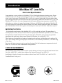
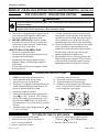
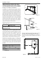
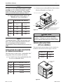
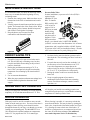
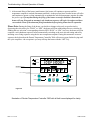
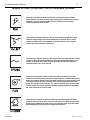
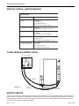
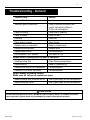
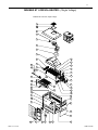
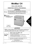
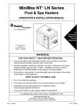
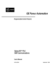
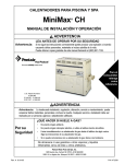
1 1
MiniMax NT Low NOx Series
®
POOL & SPA HEATERS
OPERATION & INSTALLATION MANUAL
WARNING
FOR YOUR SAFETY - READ BEFORE OPERATING
Warning: If you do not follow these instructions exactly, a fire or explosion may
result, causing property damage, personal injury or loss of life.
For additional free copies of this manual; call (800) 831-7133.
To
Consumer
Retain For
Future
Reference
U.S. Patent Numbers
5,318,007 - 5,228,618
5,201,307 - 4,595,825
WARNING
Warning: Improper installation, adjustment, alteration, service or maintenance can
cause property damage, personal injury or death. Installation and service must be
performed by a qualified installer, service agency or the gas supplier.
WHAT TO DO IF YOU SMELL GAS
For Your
Safety
•
•
•
•
Do not try to light any appliance.
Do not touch any electrical switch; do not use any phone in your building.
Immediately call your gas supplier from a neighbor's phone.
Follow the gas supplier's instructions.
If you cannot reach your gas supplier, call the fire department.
Do not store or use gasoline or other flammable vapors and
liquids in the vicinity of this or other appliances.
Pentair Pool Products, Inc.
1620 Hawkins Ave., Sanford, NC 27330 • (919) 774-4151
10951 W. Los Angeles Ave., Moorpark, CA 93021 • (805) 523-2400
Rev. C 11-1-01
P/N 471593
2
Table of Contents
Introduction ...............................................................................................................
3
Important Notices ......................................................................................................................................................................
3
Code Requirements ...................................................................................................................................................................
3
Warranty Information .................................................................................................................................................................
4
Operation ....................................................................................................................
4
Safety Rules ..............................................................................................................................................................................
4
HSI (Hot-Surface Ignition) Lighting/Operation - Natural Gas .....................................................................................................
5
Installation Instructions—Specifications .................................................................
6
Installation — Electrical .............................................................................................................................................................
7
Installation — Remotes (2 and 3 Wire) ...................................................................................................................................... 8 - 9
Installation — Wiring Diagram ................................................................................................................................................... 10 - 12
Installation — Water Connections .............................................................................................................................................. 13
Installation — Plumbing ............................................................................................................................................................. 13
Installation — Gas Line ............................................................................................................................................................. 14
Pipe Sizing Chart/Gas Pressure Requirements ......................................................................................................................... 14
Regulated Manifold Pressure Test .............................................................................................................................................
14
Venting — Indoor Installations ................................................................................................................................................... 15 - 18
Venting — Outdoor Installations ................................................................................................................................................ 19
Basic Operation — General Description .................................................................................................................................... 20
Basic Operation — Safety Controls ........................................................................................................................................... 21 - 22
Basic Operation — HSI Ignition Module .................................................................................................................................... 22
Thermostat (Programming & Layout) ........................................................................................................................................ 23
Temperature & Time Setting (Programming) ............................................................................................................................. 24 - 25
Maintenance ............................................................................................................................ 26
Maintenance Instructions ........................................................................................................................................................... 26
Pressure Relief Valve ................................................................................................................................................................ 26
Maintenance (Water Treatment) ................................................................................................................................................ 27
Trouble Shooting ....................................................................................................... 28
Normal Operation Sequence ..................................................................................................................................................... 28 - 29
Troubleshooting & Service ......................................................................................................................................................... 30 - 31
Troubleshooting (General) .........................................................................................................................................................
32
MiniMax NT Low NOx Parts List & Exploded View (Single Voltage) ......................................... 33-34
MiniMax NT Low NOx Parts List & Exploded View (Dual Voltage) ............................................ 35-36
Warranty Information .................................................................................................
P/N 471593
Back Cover
Rev. C 11-1-01
3
Introduction
MiniMax NT Low NOx
Pool and Spa Heaters
Congratulations on your purchase of a MiniMax NT Low NOx high performance heating system. Proper
installation and service of your new heating system and correct chemical maintenance of the water will
ensure years of enjoyment. The MiniMax NT Low NOx is a compact, lightweight, efficient, induced-draft,
gas fired high performance pool and spa heater that can be directly connected to schedule 40 PVC pipe. The
MiniMax NT Low NOx, also comes equipped with the Pentair multifunction temperature controller 7800
which shows, at a glance, the proper functioning of the heater. All HSI (hot-surface ignition) MiniMax NT
Low NOx heaters are designed with a direct ignition device (HSI) which eliminates the need for a standing
pilot. The MiniMax NT Low NOx requires an external power source (120/240 VAC 50/60 Hz) to operate.
IMPORTANT NOTICES
...For the installer and operator of the MiniMax NT Low NOx pool and spa heater. The manufacturer’s
warranty may be void if, for any reason, the heater is improperly installed and/or operated. Be sure to follow
the instructions set forth in this manual. If you need any more information, or if you have any questions
regarding to this pool heater, please contact Pentair Pool Products, Inc. at (800) 831-7133.
These heaters are designed for the heating of swimming pools and spas, and should never be employed for
use as space heating boilers, general purpose water heaters, in non-stationary installations, or for the heating
of salt water.
Do not use the heater to protect pools or spas from freezing if the final maintenance temperature desired is
below 60° F. as this will cause condensation related problems.
CODE REQUIREMENTS
The installation must conform with local codes or in the absence of local codes with the latest National Fuel
Gas Code, ANSI Z223.1, and the latest edition of the National Electrical Code, NFPA 70.
Installation in Canada to be made in accordance with the latest CAN/CGA-B149.1 or .2 and CSA C22.1
Canadian Electric Code, part 1.
Rev. C 11-1-01
P/N 471593
Operation
4
This instruction manual provides operating
instructions, installation and service information
for the MiniMax NT Low NOx high performance
heater. The information in this manual applies to
the MiniMax NT Low NOx 200, 250, 300, and
400 natural gas models.
It is very important that the owner/installer read
and understand the section covering installation
instructions, and recognize the local and state codes
before installing the MiniMax NT Low NOx.
History and experience has shown that most heater
damage is caused by improper installation practices.
WARRANTY INFORMATION
The MiniMax NT Low NOx pool heater is sold
with a limited factory warranty. Specific details are
described on the back cover of this manual and a
copy of the warranty and warranty registration
card are included with the product. Return the
warranty registration card after filling in the serial
number from the rating plate inside the heater.
Pentair Pool Products’ high standards of excellence
include a policy of continuous product improvement
resulting in your state-of-the-art heater. We reserve
the right to make improvements which change the
specifications of the heater without incurring an
obligation to update the current heater equipment.
Operation
SAFETY RULES
1. Spa or hot tub water temperatures should never
exceed 104° F. A temperature of 100° F. is
considered safe for a healthy adult. Special
caution is suggested for young children.
2. Drinking of alcoholic beverages before or during
spa or hot tub use can cause drowsiness which
could lead to unconsciousness and subsequently
result in drowning.
3. Pregnant women beware! Soaking in water
above 100° F. can cause fetal damage during the
first three months of pregnancy (resulting in the
birth of a brain-damaged or deformed child).
Pregnant women should stick to the 100° F.
maximum rule.
4. Before entering the spa or hot tub, the user
should check the water temperature with an
accurate thermometer. Spa or hot tub
thermostats may err in regulating water
temperatures by as much as 4° F.
5. Persons with a medical history of heart disease,
circulatory problems, diabetes or blood pressure
problems should obtain their physician's advice
before using spas or hot tubs.
6. Persons taking medication which induce
drowsiness, such as tranquilizers, antihistamines
or anticoagulants should not use spas or hot
tubs.
WARNING
Should overheating occur or the gas supply fail to shut off, turn off the manual gas control valve to the
appliance. Do not use this heater if any part has been under water. Immediately call a qualified service
technician to inspect the heater and to replace any part of control system and gas control which has been
under water.
P/N 471593
Rev. C 11-1-01
Operation (Lighting)
5
MINIMAX NT LOW NOx HSI ELECTRONIC IGNITION LIGHTING/OPERATION - NATURAL GAS
FOR YOUR SAFETY: READ BEFORE LIGHTING
WARNING
If you do not follow these instructions exactly, a fire or explosion may result causing personal injury, loss of life
and property damage.
Do not attempt to light the heater if you suspect a natural gas leak. Lighting the heater can result in a fire or
explosion which can cause personal injury, death, and property damage.
A. This heater is equipped with an ignition device
which automatically lights the main burners.
Do not try to light the burners by hand.
B. BEFORE OPERATING, smell all around
the heater area for gas. Be sure to smell next
to the floor because some gas is heavier than
air and will settle on the floor.
WHAT TO DO IF YOU SMELL GAS
- Do not try to light any heater.
- Do not touch any electrical switch; do not use
any phone in your building.
- Immediately call your gas supplier from a
neighbor's phone. Follow the gas supplier's
instructions.
- If you cannot reach your gas supplier, call the
Fire Department.
C. Use only your hand to push in or turn the gas
control knob. Never use tools. If the knob will
not push in or turn by hand, don't try to repair it.
Call a qualified service technician. Forced or
attempted repair may result in a fire or explosion.
D. Do not use this heater if any part has been under
water. Immediately call a qualified service
technician to inspect the heater and to replace
any part of the control system and any gas
control which has been under water.
E. The MiniMax NT Low NOx incorporates the
Pentair temperature controller 7800 to aid you
in the operation of the heater, and to assist in
diagnosing a failure in the heater’s function.
OPERATING INSTRUCTIONS
1.
2.
3.
4.
5.
6.
7.
8.
STOP! Read the safety information above.
Set the thermostat to the lowest setting.
Turn off electric power to the heater.
This heater is equipped with an ignition device
which automatically lights main burners. Do
not try to light the burners by hand.
Remove the control access door.
Push in gas control knob slightly and turn clockwise
to “OFF”. (If not on “OFF” position.)
Wait five (5) minutes to clear out any gas. If you
then smell gas, STOP! Follow "B" in the safety
information above. If you don't smell gas, go to the
next step.
Turn knob on gas control counterclockwise
to “ON”; see Figure 1.
9.
10.
11.
12.
Replace the control access door.
Turn on the electrical power to the heater.
Set the thermostat to the desired setting.
If the heater will not operate, follow the instructions "To Turn Off Gas To Heater" and call your
service technician or gas supplier.
Gas
Inlet
ON
OFF
Figure 1.
Gas control knob shown in “ON” position.
TO TURN OFF GAS TO APPLIANCE
1. Set the thermostat to lowest setting.
2. Turn off all electric power to the heater if
service is to be performed.
3. Remove control access door.
Rev. C 11-1-01
4. Push in gas control knob slightly and turn
clockwise
to "OFF". Do not force.
5. Replace control access door.
P/N 471593
6
Installation Instructions
SPECIFICATIONS
IMPORTANT NOTICE: These installation instructions are designed for use by qualified personnel
only, trained especially for installation of this type of heating equipment and related components. Some
states require installation and repair by licensed personnel. If this applies in your state, be sure your
contractor bears the appropriate license.
OUTDOOR VENTILATION
15.50
7.35
2 in. SOCKET
24.05
30.63
LEG
3.50
14.50
Figure 2.
LEG
"A" DIM.
21.63
250
24.63
300
27.63
400
34.13
4.875
8.84
6.64
MODEL
200
"A" DIM.
INDOOR VENTILATION
15.50
INDOOR VENT ADAPTOR
7.35
4 in. Kit
P/N 460506
P/N 460506
4 in. Kit
P/N 460507
5 in. Kit
2.00
24.05
Ø4.88
Ø5.88
5 in. Kit
P/N 460507
30.63
LEG
3.50
14.50
Figure 3.
LEG
8.84
6.64
4.875
MODEL
200
"A" DIM.
21.63
250
24.63
300
27.63
400
34.13
"A" DIM.
P/N 471593
Rev. C 11-1-01
Installation (Electrical)
7
ELECTRICAL, ALL HSI UNITS
Electrical Rating
50/60 Hz
120 V.A.C. ONLY
NOTE
The transformer is pre-wired at the factory for 120 VAC operation ,connect line
supply to the line terminal block inside junction box. Use caution in
connecting supply to proper Line (L), Neutral (N), and Ground (GND) terminals;
see below, Figure 5.
NOTE
If any of the original wiring supplied with this heater must be replaced, installer must supply
(No. 18 AWG 105° C. U.L. approved AWM low energy stranded) copper wire or it’s equivalent.
In Canada: wires must be CSA approved.
WARNING
The heater must be electrically grounded and bonded in accordance with local codes or, in the absence
of local codes, with the latest national electrical codes ANSI/NFPA No. 70.
In Canada: CSA standard C22.1 Canada Electrical Code Part 1 and/or local codes.
Always use crimp type connectors when connecting two wires.
LINE TERMINAL BLOCK
GROUND
CONNECTION
GREEN WIRE
NEUTRAL / WHITE 120 VAC
WHITE WIRE
INTERNAL
FACTORY WIRES
N
BLACK WIRE
POSITIVE LINE FOR 120 VOLTS AC
L
Figure 5.
Rev. C 11-1-01
P/N 471593
Installation (Remotes)
8
TWO-WIRE OR THREE-WIRE REMOTE HOOK-UP
Before connecting the remote control system please read the following:
1. First turn the gas valve to the "OFF" position and power up the
heater, now using the front buttons on the temperature controller,
set the "SPA" and "POOL" temperature to the maximum setting,
see Page 24.
2. Now turn the heater to the "OFF" mode by using the "OFF" button
on the temperature controller, see Page 24 or by using the main
power switch located on the bottom of the junction box.
3. With the heater in the "OFF" mode, locate the three tabs on the back
of the temperature controller as viewed from the backside,
see Figure 6.
4. • Two-wire remote with temperature control:
1
POOL
2
3
SPA
GND
Figure 6.
a) Using 3/16" female quick disconnect connectors, connect one
wire to the "GND" tab of the temperature controller, then the
second wire to either the "SPA" or "POOL" tab.
b) Now return power to the heater but leaving the temperature controller in the "OFF" position,
see Page 24. (Note: If you used the main power switch to turn off the heater, now turn the main power
switch on.) At this time the remote system has control over the heater, and will turn it on and off when
called for by the remote system thermostat thus keep the pool and spa at the desired temperature.
2 WIRE REMOTE
5 A FUSE
FOR AUX2 (PILOT DUTY ONLY)
AUX2
5A
25O V
RELAY
5 3 1
5 3 1
6 4 2
6 4 2
J2
J1
10 A
25O V
RELAY
REMOTE BLOWER
(AUX1)
1 2 3
F
3
2
1
IGN MODULE
1
2
3
4
G VALVE
1
2
3
LIMITS
1
2
3
4
POWER
5
6
1
2
TPROBE
2
}
NOT USED
3
POOL
SPA
GND
AIR PRESS
24 VAC
PRESS
H LIMIT
PV
T FUSE
PV/MV
MV
PV/MV
MV
PV
A.C LOAD (PUMP/AUX2)
(PILOT DUTY ONLY)
1 2
1
24 VAC
4
3
BLOWER (POWER) LINE
BLOWER (POWER) LINE
GND
C
SPA
TEMPERATURE
DISPLAY MODE
10 A
25O V
RELAY
PUMP/AUX2
PUMP
PURGE MODE
REMOTE SWITCH CONTROLLER
Figure 7.
Three-Wire continued on next page.
P/N 471593
Rev. C 11-1-01
Installation (Remotes)
9
TWO-WIRE OR THREE-WIRE REMOTE HOOK-UP, (cont’d.)
• Three-wire remote:
a) Using 3/16" female quick disconnect connectors, connect the common wire to the "GND" tab of the
temperature controller, then connect the two remaining wires to the temperature controller
corresponding to the remote control device, pool wire to "POOL" tab, spa wire to "SPA" tab.
b) Now return power to the heater. (Note: If you used the main power switch to turn off the heater, now
turn the main power switch on.) At this time, the remote system has control over the heater and if pool
or spa temperature is below the temperature controller setting, then the heater will try to come on.
c) If you desire to reset the temperature settings of the temperature controller, the remote has to be in the
desired mode for you to change the particular setting. Example: You wish to raise or lower the pool
temperature from the factory setting, you must have the remote system in the pool mode, if you wish to
change the spa temperature, you must have the remote system in the spa mode.
5. Now turn on the gas valve to "OPEN" position, the heater is now ready to
operate.
NOTE
The heater factory settings are 78° F. for the pool and 104° F. for the spa.
When connecting a remote control to the MiniMax, you must install the low
voltage thermostat wires in separate conduit from ANY line voltage wires.
Failure to follow these instructions will cause the thermostat relay to react
erratically. A Remote hook-up deactivates the selector keys on the front
thermostat display panel and gives selection control to the remote.
3 WIRE REMOTE
This icon is not a fault icon
but instead indicates a remote
switching device is connected
to the Pentair Temperature
Controller 7800, and has
overriding selection control
of Pentair Temperature
Controller 7800.
5 A FUSE
FOR AUX2 (PILOT DUTY ONLY)
AUX2
PUMP
PURGE MODE
5A
25O V
RELAY
5 3 1
5 3 1
6 4 2
6 4 2
10 A
25O V
RELAY
PUMP/AUX2
J2
J1
1 2 3
C
F
1
2
3
4
G VALVE
1
2
3
LIMITS
1
2
3
4
POWER
5
6
1
2
REMOTE
(AUX1)
TPROBE
A.C LOAD (PUMP/AUX2)
(PILOT DUTY ONLY)
}
NOT USED
3
POOL
SPA
GND
AIR PRESS
2
BLOWER (POWER) LINE
POOL
24 VAC
PRESS
H LIMIT
PV
T FUSE
PV/MV
MV
PV/MV
MV
PV
4
3
1 2
1
24 VAC
10 A
25O V
RELAY
BLOWER
BLOWER (POWER) LINE
GND
3
2
1
IGN MODULE
SPA
TEMPERATURE
DISPLAY MODE
REMOTE POOL/OFF/SPA
THERMOSTAT SELECT SWITCH
Figure 8.
OL
PO
A
SP
COMMON
Rev. C 11-1-01
P/N 471593
B
NEU
120 VAC
(ONLY)
HOT
ORG
WHT
SWITCH
LOW GAS PRES.
ORG
SWITCH
HI AIR PRES.
ORG
2
1
AUX2
10A
250V
RELAY
10A
250V
RELAY
BLOWER
REMOTE
AIR PR SW.
TPROBE
TEMPERATURE
PROBE
WHT
ORG
LIMITS
6 5 4 3 2 1
POWER
2 1
P7
P4
WHT
1
2
ORG
BLK
BLK
GRN
WATER PRESSURE
SWITCH
W2
WHT
RED
RED
1
2
3
4
5
6
SWITCH
ORG
W1
EXHAUST HIGH LIMIT
THERMAL SWITCHES
3 2 1
G VALVE
P10
1
2
3
LOW AIR PRES.
ORG
FROM
TERM
BLOCK
FROM
TERM
BLOCK B
RED
HIGH LIMIT
THERMAL SWITCHES
CHASSIS
SHEET METAL
4 3 2 1
IGN MODULE
P11
ORG
BLU
WHT
RED
C
5A
250V
RELAY
3 2 1
F
2
1
3
ORG
WHT
RED
BLK
ORG
ORG
WHT
WHT
F1
PH
PL
PC
WHT
RED
BLU
ORG
FAN CON. BOARD
RET
FL
FH
24VAC
FC
RED
WHT
BLU
F2
THERMAL FUSE
ORG
WHT
TERMINATE SUPPLY SAFETY GROUND WIRE (GREEN) HERE
GROUND SCREW WITH PAINT CUTTING WASHER
N
GRN
VAL
TH
S2
L2
L1
(HOT)
5
4
HOT SURFACE
IGNITOR
HOT SURFACE
IGNITOR
WHT
GRN
IGN MODULE
BURNER
S1
GAS VALVE
3
2
1
TERM
BLOCK B
(NEU)
BLK
BLK
WHT
HI SPEED
EXTERNAL
BOND LUG
BLK
IF ORIGINAL FACTORY WIRING MUST BE REPLACED, INSTALLER MUST SUPPLY
UL OR CSA (IF CANADA) APPROVED WIRE, 18 GAUGE, 600V, 105 C TEMPERATURE RATING.
THERMAL FUSE WIRING MUST BE REPLACED WITH UL OR CSA (IF CANADA) APPROVED
WIRE, 18 GAUGE, 600V, 125 C TEMPERATURE RATING.
INTERCONNECTING WIRING TO APPLIANCE MUST CONFORM TO THE NATIONAL ELECTRICAL
CODE OR SUPERCEDING LOCAL (WIRING) CODES.
4
COM
3
SPA
1
2
POOL
NEU
HOT
2
3
SUPPLY 120 VAC
(ONLY)
DUAL
SPEED
FAN
(HOT)
GRN
1
TERM
BLOCK A
LOW SPEED
COM
P/N 471593
WHT
MiniMax NT 400 LOW NOx WIRING DIAGRAM
Installation (Single Voltage Wiring)
10
MiniMax NT Low NOx 400 HSI Electronic Ignition Wiring Diagram
(SINGLE VOLTAGE)
Rev. C 11-1-01
BLK
ORG
ORG
2
1
BLK
BLK
AUX2
10A
250V
RELAY
10A
250V
RELAY
BLOWER
REMOTE
AIR PR SW.
GRN
WATER PRESSURE
SWITCH
WHT
TPROBE
LIMITS
6 5 4 3 2 1
2 1
P7
P4
RED
POWER
ORG
TEMPERATURE
PROBE
W2
WHT
WHT
1
2
WHT
W1
RED
1
2
3
4
5
6
LOW GAS PRES.
SWITCH
HI AIR PRES.
SWITCH
NEU
120 VAC
(ONLY)
HOT
RED
EXHAUST HIGH LIMIT
THERMAL SWITCHES
3 2 1
G VALVE
PI0
4 3 2 1
IGN MODULE
P11
RED
ORG
BLU
WHT
WHT
WHT
C
5A
250V
RELAY
3 2 1
F
2
1
3
F1
RED
WHT
BLU
WHT
RED
BLU
ORG
F2
THERMAL FUSE
CODE OR SUPERCEDING LOCAL (WIRING) CODES.
N
(HOT)
GRN
VAL
TH
S2
L2
L1
5
4
3
2
1
BLK
WHT
TERM B
BLOCK
HOT SURFACE
IGNITOR
WHT
GRN
IGN MODULE
BURNER
S1
GAS VALVE
INTERCONNECTING WIRING TO APPLIANCE MUST CONFORM TO THE NATIONAL ELECTRICAL
WIRE, 18 GAUGE, 600V, 125 C TEMPERATURE RATING.
THERMAL FUSE WIRING MUST BE REPLACED WITH UL OR CSA (IF CANADA) APPROVED
UL OR CSA (IF CANADA) APPROVED WIRE, 18 GAUGE, 600V, 105 C TEMPERATURE RATING.
IF ORIGINAL FACTORY WIRING MUST BE REPLACED, INSTALLER MUST SUPPLY
1
2
3
ORG
TERM B
BLOCK
FROM
TERM B
BLOCK
FROM
RED
HIGH LIMIT
THERMAL SWITCHES
CHASSIS
SHEET METAL
TERMINATE SUPPLY SAFETY GROUND WIRE (GREEN) HERE
GROUND SCREW WITH PAINT CUTTING WASHER
MiniMax NT 250 LOW NOx WIRING DIAGRAM
4
SPA
3
COM
1
2
POOL
BLK
(NEU)
BLK
NEU
SUPPLY 120 VAC
(ONLY)
HOT
2
3
FAN
(HOT)
GRN
1
BLK
WHT
TERM A
BLOCK
WHT
WHT
Rev. C 11-1-01
BLK
EXTERNAL
BOND LUG
Installation (Single Voltage Wiring)
11
MiniMax NT Low NOx 250 HSI Electronic Ignition Wiring Diagram
(SINGLE VOLTAGE)
P/N 471593
EXTERNAL
BOND LUG
ORG
AIR PRESSURE SW.
1
2
RELAY
WHT
AUX2
10A
250V
RELAY
10A
250V
RELAY
BLOWER
REMOTE
AIR
PRESS SW.
GRN
WATER PRESSURE
SWITCH
RED
TPROBE
TEMPERATURE
PROBE
WHT
WHT
WHT
GAS
VALVE
6 5 4 3 2 1
POWER
2 1
3 2 1
P10
P7
P4
RED
RED
TFUSE
LIMITS
ORG
WHT
WHT
EXHAUST HIGH LIMIT
THERMAL SWITCHES
1
2
GRN
ORG
WHT
HIGH LIMIT
THERMAL SWITCHES
1
2
3
4
5
6
WHT
GAS PRESSURE SW.
RED
CHASSIS
SHEET METAL
4 3 2 1
IGN
MODULE
P11
C
5A
250V
RELAY
3 2 1
F
2
1
3
ORG
BLU
WHT
RED
RED
WHT
BLU
F1
F2
THERMAL FUSE
WHT
RED
BLU
ORG
BLK/WHT
BLK
RED
RED/WHT
GRN
WHT
YEL
BLU
BLK
WHT
(WHT)
CON-2M
GND
MV1
TH
LO/FS
S2
L2
L1
S1/240
S1/120
IGN MODULE
BURNER
HOT SURFACE
IGNITOR
GAS VALVE
WHT
TERMINATE SUPPLY SAFETY GROUND WIRE (GREEN) HERE
GROUND SCREW WITH PAINT CUTTING WASHER
BLK
(BRN)
BLOWER
PUR
ORG
BLK
BLK
CON-2F
FOR 240 VAC
YEL
(BLU)
CON-2F
WHT
WHT
FOR 120 VAC
WHT
BLK
5
4
3
2
1
WHT
BLK
BLK
GRN
WHT
TERM B
BLOCK
IF ORIGINAL FACTORY WIRING MUST BE REPLACED, INSTALLER MUST SUPPLY
UL OR CSA (IF CANADA) APPROVED WIRE, 18 GAUGE, 600V, 105˚ C TEMPERATURE RATING.
THERMAL FUSE WIRING MUST BE REPLACED WITH UL OR CSA (IF CANADA) APPROVED
WIRE, 18 GAUGE, 600V, 200˚ C TEMPERATURE RATING.
INTERCONNECTING WIRING TO APPLIANCE MUST CONFORM TO THE NATIONAL ELECTRICAL
CODE OR SUPERCEDING LOCAL (WIRING) CODES.
1
2
3
COM
4
SPA
3
WHT
P/N 471593
1
2
POOL
MiniMax NT LOW NOx ALL MODELS WIRING DIAGRAM
3
2
1
TERM A
BLOCK
BLK
WHT
GRN
240 VAC
OR
120 VAC
Installation (Dual Voltage Wiring)
12
MiniMax NT Low NOx (ALL MODELS) HSI Electronic Ignition Wiring Diagram
(DUAL VOLTAGE)
PUMP RELAY
Rev. C 11-1-01
Installation (Plumbing)
13
WATER CONNECTIONS
Reversible Inlet/Outlet Connection
The MiniMax NT Low NOx heater is factory
assembled with right side inlet/outlet water
connections. The inlet/outlet header can be reversed
for left side water connections without removing the
heat exchanger.
Reversing Water Connections
Tools required:
1/4 in. Screw Driver
9/16 in. Socket and Wrench
1/2 in. & 9/16 in. Open Wrench
1. Remove the right and left large inspection plates.
2. Disconnect all wires from the high-limit
switches except the short jumper wire.
3. Disconnect the pressure switch wiring.
4. Remove the temperature sensing bulb from the
inlet/outlet header. Note: If needed, you may cut
the wire ties holding them together.
5. Remove the 16 bolts holding the main inlet/
outlet head and return head in place, exchange
the heads, using the new tube seals supplied
with the heater, re-install the 16 bolts using
moderate torque.
6. Install the temperature sensing probe by passing
the wires through the hole provided on the left
side of the brace panel. Route wires through the
support bracket.
7. Reconnect all the high limit wires and the
pressure switch wiring, routing the wires
through the same hole as the thermostat sensor
wires.
8. Re-install the two large inspection plates on the
appropriate side.
VALVES
When any equipment is located below the surface of
the pool or spa, valves should be placed in the
circulation piping system to isolate the equipment
from the pool or spa.
Check valves are recommended to prevent back
siphon.
CAUTION
Exercise care when installing chemical feeders so
as to not allow back siphoning of chemical into the
heater, filters or pump.
Rev. C 11-1-01
FILTER
MANUAL
BY-PASS
CHECK
VALVE
GATE
VALVE
Figure 9.
CHECK
VALVE
FROM
POOL
PLUMBING CONNECTIONS
The MiniMax NT Low NOx heater has the unique
capability of direct schedule 40 PVC plumbing
connections. A set of bulkhead fittings is included with
the MiniMax NT Low NOx to insure conformity with
Pentair’s recommended PVC plumbing procedure.
Other plumbing connections can be used.
CAUTION
Before operating the heater on a new installation,
turn on the circulation pump and bleed all the air
from the filter using the air relief valve on top of the
filter. Water should flow freely through the heater.
Do not operate the heater unless water in the pool/
spa is at the proper level.
MANUAL BY-PASS
Where the flow rate exceeds the maximum 120
GPM, a manual bypass should be installed and
adjusted. After adjustments are made, the valve
handle should be removed to avoid tampering.
Model
PLUMBING
PUMP
TO
POOL
POOL
HEATER
Min. (GPM) Max. (GPM) *
200
20
120
250
30
120
300
30
120
400
40
120
* Do not exceed the maximum recommended
flow rate for the connecting piping.
BELOW POOL INSTALLATION
If the heater is below water level, the pressure
switch must be adjusted. This adjustment must be
done by a qualified service technician. See Page 22,
Figure 20.
P/N 471593
Installation (Gas Line)
GAS CONNECTIONS
14
Pipe Sized For Length Of Run In Equivalent Feet
GAS LINE INSTALLATIONS
Model
Before installing the gas line, be sure to
200
check which gas the heater has been
250
designed to burn. This is important
300
because different types of gas require
400
different gas pipe sizes. The rating plate
on the heater will indicate which gas the
heater is designed to burn. Table 1, shows which
size pipe is required for the distance from the gas
meter to the heater. The table is for natural gas at a
specific gravity of .65.
When sizing gas lines, calculate three (3) additional
feet of straight pipe for every elbow used.
When installing the gas line, avoid getting dirt,
grease or other foreign material in the pipe as this
may cause damage to the gas valve, which may
result in heater failure.
The gas meter should be checked to make sure that
it will supply enough gas to the heater and any other
appliances that may be used on the same meter.
1/2 in.
3/4 in.
1 in.
LP
1¼ in.
Nat
LP
The heater and its gas connection must be leak
tested before placing the heater in operation. Do not
use flame to test the gas line. Use soapy water or
another nonflammable method.
A manual main shut-off valve must be installed
externally to the heater.
1½ in.
2 in.
Nat
LP
Nat
LP
Nat
-
20'
30'
80'
125' 250' 450' 600'
-
10'
20'
50'
70'
150' 250' 500' 600'
-
-
10'
30'
50'
100' 200' 350' 400' 600'
-
-
-
10'
20'
60'
Nat
LP
Nat
LP
-
-
-
-
-
-
-
-
-
100' 150' 200' 450' 400'
-
REGULATED MANIFOLD PRESSURE TEST
1. Attach the manometer to the heater jacket.
2. Shut off the main gas valve.
3. Remove 1/8 in. NPT plug on the outlet side of the
valve and screw in the fitting from the manometer kit.
4. Connect the manometer hose to the fitting.
5. Turn on the heater.
6. The manometer must read 4 in. WC for natural gas,
while operating.
7. For adjustment, remove the Regulator Adjustment
Cap and using a screwdriver turn the screw clockwise to increase - counterclockwise to decrease gas
pressure.
Regulator Adjustment Cap
1/8" NPT Plug
(Inlet Press)
The gas line from the meter will usually be of a
larger size than the gas valve supplied with the
heater. Therefore a reduction of the connecting gas
pipe will be necessary. Make this reduction as close
to the heater as possible.
The heater and any other gas appliances must be
disconnected from the gas supply piping system
during any pressure testing on that system, (greater
that ½ PSIG).
Table 1.
ON
OFF
1/8" NPT Plug
(Manifold Press)
Figure 10.
CAUTION
The use of Flexible Connectors (FLEX) is NOT
recommended as they cause high gas pressure drops.
MINIMAX NT LOW NOx GAS PRESSURE REQUIREMENTS*
Natural
WARNING
Do not install the gas line union inside the heater
cabinet. This will void your warranty.
Maximum inlet gas pressure
Minimum inlet gas pressure
Normal manifold pressure
10 in. WC
**5 in. WC
4 in. WC
*All Readings are taken with the heater fired. Any adjustments
or readings made with heater off will give incorrect readings.
** 6 WC for 400 model
P/N 471593
Rev. C 11-1-01
Installation (Indoor)
15
INDOOR VENTING—General Requirements
The vent pipe must be the same size or larger. The MiniMax NT Low NOx heaters are capable of a 360-degree
discharge rotation and operate with a positive vent static pressure and with a vent gas temperature less than 400°
F. The total length of the horizontal run must not exceed the length that is listed below in the tables.
Please note the allowable vent runs for each stack pipe diameter are different and can not be exceeded.
Note that each 90-degree elbow reduces the maximum horizontal vent run by 8 feet and each 45-degree elbow
in the vent run reduces the maximum vent run by 4 feet. See the tables below for the maximum vent lengths
using a 90-degree and 45-degree elbows. The MiniMax NT Low NOx induced-draft pool and spa heater uses
positive pressure to push flue gases through the vent pipe to the outside. This requires a completely sealed vent
system—single wall vent pipe with sealed-seams and joints may be used. Flue gases under positive pressure
may escape into the dwelling with any cracks or loose joints in the vent pipe, or improper vent installation.
The vent pipe must be of a sealed-seam construction such as those listed for use with category III appliances.
Alternately, single wall or double-wall type B duct which has had duct seams and joints permanently sealed
using cements or other suitable means which are rated for use at the flue gas temperatures of 325° F. and are
permanent are acceptable. The use of listed thimbles, roof jacks and/or side vent terminals are required; and the
proper clearances to combustible materials must be maintained in accordance with type of vent pipe employed—
in the absence of a clearance recommendation by the vent pipe manufacturer, the requirements of the Uniform
Mechanical Code should be met. The ventilation air requirements for the MiniMax NT Low NOx heater and
can be found on page 17. It is recommended that vent runs over 18 feet be insulated to reduce condensation
related problems and/or the use of a condensate trap in the vent run close to the heater may be necessary in
certain installations such as cold climates. The MiniMax NT Low NOx is suitable for through-the-wall venting.
Recommended sources for Side-wall vent hood terminals include: The Field Controls Co. (2308 Airport Road,
Kingston, NC 28501, (800)742-8368) and Tjernlund Products Inc. (1601 Ninth Street, White Bear Lake, MN
55110, (800) 255-4208)—consult manufacturer for model information and availability.
CAUTION
Do NOT combine exhaust vent pipes to a common exhaust vent in multiple unit installations. Run separate vent pipes.
45 ft. Maximum Vent Run, 5 in. O.D. vent (Equiv. ft.)
Additional 90° elbows
after first elbow
Additional 45° elbows
after first elbow
22 ft. Maximum Vent Run, 4 in. O.D. vent (Equiv. ft.)
Additional 90° elbows
after first elbow
Additional 45° elbows
after first elbow
Quantity
Reduced Max.
Quantity
Reduced Max.
Quantity
Reduced Max.
Quantity
Reduced Max.
1 (2 total)
37
(2 total)
41
1 (2 total)
14 ft.
(2 total)
18 ft.
2 (3 total)
29
(3 total)
37
2 (3 total)
—
(3 total)
14 ft.
3 (4 total)
21
(4 total)
33
3 (4 total)
—
(4 total)
—
Rev. C 11-1-01
P/N 471593
;;;
;;;
;;;
Installation (Indoor)
16
INDOOR INSTALLATION (USA ONLY)
OUTDOOR SHELTER INSTALLATION (CANADA)
See page 17 for (Indoor) Vent Adaptors
10 ft.
Ridge
Vent
Cap
2 ft. min.
All products of combustion and vent gases must be
completely removed to the outside atmosphere through
a vent pipe which is connected to the stack adaptor. A
vent pipe extension of the same size must be connected
to the indoor stack adaptor and extended at least 2 feet
higher than highest point of the roof within a 10 foot
horizontal radius, and at least 3 ft. higher than the point
at which it passes through the roof, or as permitted by
local code; see Figures 11 and 12. The vent should
terminate with an approved vent cap (weather cap) for
protection against rain or blockage by snow. Doublewall vent pipe and an approved roof jack shall be
employed through the roof penetration.
3 ft. min.
Roof
Jack
Chimney
Figure 11.
VENT CAP AND
RISER FURNISHED
BY INSTALLER
The heater must be located as close as practical to a
chimney or gas vent.
AIR SUPPLY
VENTILATION
CAUTION
The heater should be installed at least 5 feet away
from the pool or spa.
The heater must be placed in a suitable room on a noncombustible floor or on a non-combustible base and in
an area where leakage from heat exchanger or water
connections will not result in damage to the area
adjacent to the heater or the structure. When such
locations cannot be avoided, it is recommended that a
suitable drain pan with adequate drainage, be installed
under the heater. The pan must not restrict air flow.
AIR SUPPLY
GAS COMBUSTION
OPTIONAL SIDE WALL VENT NT
The heater should not be installed closer than 6 inches to
any fences, walls or shrubs at any side or back, nor
closer than 18 inches at the plumbing side. A minimum
clearance of 24 inches must be maintained at the front of
the heater.
Installations in basements, garages, or underground
structures where flammable liquids may be stored must
have the heater elevated 18 inches from the floor using
a non-combustible base. The following minimum
clearances from combustible materials must be
provided.
Remaining
Ceiling Clearance
Front
Back
Top
18 in.
24 in.
-
-
6 in.
-
6 in.
-
-
-
-
18 in.*
6"
DOOR
Water Connection
Side
Figure 12.
6"
24"
*To ceiling or roof.
18"
Figure 13.
P/N 471593
Rev. C 11-1-01
Installation (Indoor)
17
NOTE
The heater requires two uninterrupted air supply
openings; one for ventilation and one to supply
oxygen for proper gas combustion. The air supply
openings should be sized according to Table 2.
b) Construct a non-combustible base from masonry
blocks as illustrated, see Figure 14.
BASE FOR USE ON COMBUSTIBLE FLOORS
Air supply requirements below apply to all
MiniMax NT Low NOx heaters*.
.
in
REQUIRED AIR SUPPLY
6"
M
.
in
Model
Air for Combustion
Sq. In.
Air Ventilation
Sq. In.
200
200
200
250
250
250
300
300
300
400
400
400
6"
M
SHEET METAL
Table 2.
*NOTE
The openings listed in Table 2 are free open vent
area—if the vents incorporate restrictive louvers,
the vent openings must be increased to
compensate for the area blocked by the louvers (or
grills).
INSTALLATION ON FLOORS CONSTRUCTED
OF COMBUSTIBLE MATERIALS
The heater may be placed on a “combustible floor”
using either of the two methods listed below:
BLOCKS
HOLLOW MASONARY BLOCKS, NOT LESS THAN 4" THICK
(LAID WITH ENDS UNSEALED AND JOINTS MATCHED
FOR AIR CIRCULATION). COVER BLOCKS WITH
24 GA. (MIN.) GALVANIZED SHEET METAL.
Figure 14.
CAUTION
Chemicals should not be stored near the heater
installation. Combustion air can be contaminated by
corrosive chemical fumes which can void the warranty.
INDOOR VENT ADAPTORS
(FITS ALL MODELS)
The proper draft hood and adapter must be installed on
the heater as shown below and on pages 15 and 16:
Product No.
Vent Dia.
460506
4 in.
460507
5 in.
a) Use Listed Factory Non-combustible Base Kit
for use on combustible floors.
Model
Non-Combustible Base Kit
200
471961
250
460509
300
471960
400
460508
Indoor Vent
Adaptor
Figure 15.
Rev. C 11-1-01
P/N 471593
P/N 471593
Detail H
Chimney
3 ft. min.
L
K
J
;;
;;
2 ft. min.
Vent
Cap
may use a single wall vent pipe with
permanently sealed seams and joints.
must be suitable for use with category III
appliances which have flue gas temperatures
of less than 400 deg. F.
must be the same diameter as the
vent connector.
Vent pipe extension:
L must terminate with an approved (listed)
roof jack, storm collar, and vent/weather cap.
K must use a double-wall vent pipe through
the roof penetration.
J must extend at least 3 ft. higher than the
point at which it passes through the roof,
or as permitted by local code.
Vent for roof penetration installations:
Ridge
10 ft.
vent terminated at
least 24" above
any object within 10 ft.
4'
7'
Air Supply
Combustion
Air Supply
Ventilation
G
G
F
4'
D
1' min.
1' min.
3'
B
Vent Hood
1' min.
above grade
C
Recommended sources for
side wall Vent Hood; see page 15,
Section Venting.
Vent Hood
F
(Table 2 on page 17.)
G See Air Supply Requirements Table.
Air Supply
Figure 16.
must be located the following distances away from any door, window, or gravity air inlet:
D 4 ft. below
E 4 ft. horizontally
F 1 ft. above
A must be not less than 7 ft. above public walkways.
B must be at least 3 ft. above any outside air intake located within a 10 ft. radius.
must NOT be within 3 ft. of an inside corner of the structure.
C must be at least 1 ft. above grade.
Vent termination for side wall installations:
Walkway
A
Vent Hood
E
H
INDOOR INSTALLATIONS
MINIMAX NT LOW NOx VENTING GUIDELINES
Installation (Indoor)
18
Rev. C 11-1-01
Installation (Outdoor)
19
VENTILATION
OUTDOOR INSTALLATION ONLY (Outdoor Shelter Installation in Canada, see page 16)
For outdoor installation with built in vent, the heater must be placed in a suitable area on a level, noncombustible
surface. Do not install the heater under an overhang with clearances less than 3 feet from the top of the heater. The
area under an overhang must be open on three sides.
Maintain minimum clearances as indicated below. Install a minimum of 4 feet below, and 4 feet horizontally from any
opening to a building, see Figure 17.
IMPORTANT!
When locating the heater, consider that high winds can roll over or deflect off adjacent buildings
and walls. Normally, placing the heater at least three feet from any wall will minimize downdraft.
NOTE
This unit shall not be operated outdoors at temperatures below -20o F. for natural gas.
OUTDOOR INSTALLATION
MINIMAX NT VENTING GUIDELINES
D
A
1'
4'
3'
4'
B
Property Line
C
E
4'
Walkway
E
Check local building codes
for setback requirements.
Figure 17.
Vent Termination:
Must be not less than 7 ft. above public walkways.
A Must be at least 3 ft. above any forced
air inlet located within a 10 ft. radius.
Must be located the following distances away
from any door, window, or gravity air inlet:
B 4 ft. below, or
C 4 ft. horizontally, or
D 1 ft. above
Rev. C 11-1-01
P/N 471593
Basic Operation
20
GENERAL DESCRIPTION
The MiniMax NT Low NOx Pool and Spa Heater is a fan-assisted induced draft appliance. The MiniMax
NT Low NOx is available in 200,000, 250,000, 300,000 and 400,000 btu/hr. capacities and are certified for
both indoor and outdoor installations. The MiniMax NT Low NOx version natural gas pool heater must be
used for installations in the South Coast Air Quality Management District (SCAQMD)—these heaters are
certified to comply with SCAQMD Rule 1146.2 and also meet Ventura Co. APCD Rule 74.11.1.
The MiniMax NT Low NOx is designed to operate both in stackless outdoor installations and in indoor
stack vent installations—the indoor installation may be made using Kit 460506 or 460507; see pages 6 and
17, vertical vent pipe or with a horizontal vent pipe and a Listed side-wall vent.
BASIC SYSTEM OPERATION
TO OPERATE HEATER
1.
Start pump, make sure the pump is running and is primed, to close water pressure switch and
supply power to heater.
2.
Set thermostat to lowest setting by using up/down arrow keys. See page 24.
3.
Push the off key on the Pentair temperature controller 7800 (the amber “off “ led will illuminate).
See page 24.
4.
Open the access doors.
5.
Push in the gas control knob slightly and turn the knob clockwise to “OFF”. See page 5 Natural Gas
Instructions.
6.
Wait (5) minutes to clear out any gas. If you then smell gas STOP. Follow the safety information
(stated earlier in the lighting instructions section). If you don’t smell gas, go to the next step. See
page 5 Natural Gas Instructions.
7.
Turn the knob on the gas control counter clockwise to the “ON” position. See page 5 Natural Gas
Instructions.
8.
Replace the doors.
9.
Push either the “Pool” or “Spa” key to start the heater. NOTE: “Pool” key is Factory set at 78° and
“Spa” key is set at 104°.
10. Set the thermostat if needed by using the up/down arrows to set the desired temperature.
a. Fan motor starts, which closes draft proving switch.
b. Ignition module is energized after fan prepurge cycle is completed approximately 2 minutes.
c. Check for powering up the (glow coil) hot-surface ignitor by viewing through the sight glass.
11.
The ignitor will warm up and then gas valve opens to ignite the main burners.
12. Heater will operate until desired temperature is reached.
P/N 471593
Rev. C 11-1-01
Basic Operation
21
SAFETY CONTROLS
AIR PRESSURE (FAN) SWITCH
The air pressure switch is a safety device used to insure
that the blower (fan) is operating and has been
designed to monitor the vacuum (negative) pressure
within the blower housing. The air pressures switch
is factory set and is in the ignition module circuit—
the ignition module does not operate unless the air
pressure switch and all safety switches are closed.
NOTE
Some models of MiniMax NT Low NOx heaters,
manufactured before 10-15-01, used both a HIGH
and LOW air pressure switch.
Figure 18.
AIR PRESSURE SWITCH
WATER PRESSURE SWITCH
The water pressure safety switch closes when there is
a sufficient flow of water to the heat exchanger to
safely operate the heater. The switch operation must
be verified during initial operation of the heater after
installation—the switch is set at 1 PSIG and the switch
contacts must not be closed in the absence of water
flow. NOTE: See, Below Pool Level Installation
instructions on page 13. The switch may remain closed
with no water flow if there is more than a 3 ft. elevation
difference between the heater (heat exchanger) and
the pool water line—if this is the case, the water
pressure switch must be reset to maintain open switch
contacts with no water flow.
Figure 19.
Adjustment Knob
Typical Water Pressure Switch
NOTE
If the pool is more than one floor above or one floor
below the heater, the pressure switch may have to
be replaced with a flow switch.
LOW GAS PRESSURE SWITCH
(LOW NOx Versions Only)
The MiniMax NT Low NOx heater uses a low gas
supply pressure switch, ahead of the gas valve, to
prevent operation of the heater when the gas supply
pressure is below the minimum required for proper
operation of the burners. The switch is factory set. In
the event that the switch does not close and prevents
the firing of the heater, the cause of the low gas supply
pressure must be corrected. Typical causes are
undersized supply piping, undersized gas meter or low
gas regulator setting (gas supply regulator and gas
meter problems are typically corrected by your local
gas company).
Rev. C 11-1-01
Figure 20.
Low Gas Pressure Switch
P/N 471593
Basic Operation
22
SAFETY CONTROLS, (cont’d.)
IGNITION MODULE
The Ignition Module is microprocessor based and operates on 24 VAC supplied by the transformer. The
control utilizes a microprocessor to continually and safely monitor, analyze, and control the proper operation
of the gas burners. The module with the presence of the flame sensor/ignitor or remote sensor, using flame
rectification, allows the heater to operate.
HIGH LIMITS
A “High Limit”, is a safety device that opens the electrical circuit and shuts off the heater based on a
temperature set point within the “High Limit Device”. The MiniMax NT Low NOx series of heaters
contains three (3) high limit devices, two (2) are located on the main inlet / outlet header, one sensing the
inlet water temperature and one sensing the outlet water temperature. The third high limit is located on the
exhaust outlet and senses the temperature of the flue gas.
OPERATION OF IGNITION MODULE
HEAT MODE
• When a call for heat is received from the thermostat supplying 24 VAC to the “W” module terminal, the
control will perform a self check routine, flash the diagnostic LED, on units manufactured prior to
10-15-01, (located on the module) for up to four seconds and begins the safety timing ignition sequence.
After the fan prepurge cycle, the hot surface ignitor is activated for a heat-up period followed by
energization of the gas valve for the trial for ignition period.
• When flame is detected during the trial for ignition, the ignitor is deactivated and the gas valve remains
energized. The thermostat and main burner flame are constantly monitored to assure the system
continues to operate properly. When the thermostat is satisfied and the demand for heat ends, the main
valve is de-energized immediately.
FAILURE TO LIGHT-LOCK OUT
Should the main burner fail to light, or flame is not detected during the trial for ignition period, the control
will go into lockout and the gas valve will be turned off immediately. The thermostat controller will display
a flame failure error (icon/service LED) and recovery from lockout requires a manual reset by either
resetting the 7800 Thermostat or removing 24 VAC from the system by turning off main power switch
(located on the junction box behind right door) for a period of 5 seconds.
FLAME FAILURE—RE-IGNITION
If the established flame signal is lost while the burner is operating, the control will respond within 1 second.
The gas valve is de-energized and the control starts a new ignition sequence in an attempt to relight the
burner. If the burner does not relight, the control will go into lockout, requiring a manual reset.
P/N 471593
Rev. C 11-1-01
Thermostat (Programming & Layout)
23
MINIMAX NT LOW NOx PENTAIR TEMPERATURE CONTROLLER 7800
(See Figure 21, for keypad and Pentair Temperature Controller layout details.)
GENERAL
The MiniMax NT Low NOx Pentair Temperature Controller 7800 is the heart of the
control system. It controls all functions of the heater after first verifying that all safety
controls are functioning normally. If a malfunction is detected, the Pentair Temperature
Controller 7800 will flag the error with both the RED “Service” LED lighting and a
corresponding LCD icon appearing on the Pentair Temperature Controller 7800, pin
pointing the affected safety control(s). NOTE: The exception is the AUX (REMOTE)
LCD icon which appears when a REMOTE Control (or Remote Switch) is connected to
the Pentair Temperature Controller 7800, which overrides the “POOL” and “SPA” keypads
on the control, giving “ON” selection control to the REMOTE.
BASIC THERMOSTAT OPERATION
This icon is not a fault icon
but instead indicates a remote
switching device is connected
to the Pentair Temperature
Controller 7800, and has
overriding selection control
of Pentair Temperature
Controller 7800.
The Pentair Temperature Controller 7800 comes pre-programmed for use with the spa
temperature set at 104° F. and the pool temperature set for 78° F.— and with default
display mode set to display degrees F. (this may be adjusted to display in degrees C. with jumper on back of board), see
Figure 21.
You need not do anything further to enjoy your heater other than set it in the pool or spa mode by depressing the key
located under the corresponding “POOL” or “SPA” LED light. The LED above the selection will light and the
corresponding “POOL” or “SPA” LCD icon on the display will appear.
NORMAL OPERATION (NO REMOTE)
Each temperature setting in either POOL or SPA mode is settable independently.
If the Factory’s presetting of 78° F. for “Pool” and 104° F. for “Spa” is not desirable, you may adjust these settings. See
page 24 for changing the Factory Temperature Settings. To set the temperature while in SPA mode press the TEMP UP
key (with UP arrow) to increase or TEMP DOWN (with DOWN arrow) to decrease the set temperature to that desired.
NOTE: The left hand display indicates the current real-time temperature. To set the temperature for POOL mode, first
switch to POOL mode by depressing the “POOL” key and repeat the temperature setting procedure in this example. The
Pentair Temperature Controller 7800 remembers the last set temperature for both the POOL and SPA mode and you may
cycle between the two settings with the POOL and SPA selector keys.
In NORMAL operation, pressing the MODE key allows you the cycle between the right-hand display showing the SET
TEMP for the currently active POOL or SPA or the TIME.
(Pentair Temperature Controller 7800 Layout)
FLASH IN PROGRAM MODE
DAY ICON
DISPLAY IN TIME MODE ONLY
ALTERNATE DISPLAY C or F.
F = FAHRENHEIT
C = CELSIUS
ALTERNATE DISPLAY
F = FAHRENHEIT
C = CELSIUS
P = P.M.
BLANK = A.M.
SYSTEM
NORMAL
POWER
SERVICE
HEAT
CURRENT TEMP
SET TEMP/TIME
POOL OR SPA
(DISPLAY ALTERNATELY
ON LCD TO SHOW ACTIVE SELECTION)
IGN
H-LMT
PRESS
FAN
AUX
TFUSE
FAULT CONDITION LCD ICONS
SET
POOL
PROGRAM
MODE
Figure 21.
Rev. C 11-1-01
OFF
TEMP
SPA
STEP
TEMP
KEYPAD SWITCHES
P/N 471593
Temperature & Time Setting (Programming)
24
TO CHANGE THE FACTORY TEMPERATURE SETTINGS:
1. Before changing the temperature, make sure the “Temperature” is in the right window, see pages 24
and 25, if “Time” is displayed, press the MODE key to change to the “Temperature Mode”.
SET
PROGRAM
MODE
2. To change the Pool Temperature setting, press the POOL key.
POOL
OFF
SPA
3. To Raise or Lower the Pool Temperature setting, press the proper TEMP key
until the desired setting is displayed.
TEMP
STEP
NOTE: During Programming of the Pool Temperature, the two buttons on the
right are used to
or
the display setting numbers.
Increase
Decrease
Raise
Lower
(
) (
TEMP
)
NOTE: Pool Temperature is now set.
4. You can leave the right window displaying the set “Temperature” or by pressing
the MODE key, you can return to the “Time” Mode.
TEMP
STEP
NOTE: To re-set the Spa Temperature, follow the above steps 1. through 4.
while in the “Spa Heating” Mode.
TEMP
TIME SETTING
1. Make sure heater is turned “OFF” and not in the POOL or SPA “ON” Mode.
POOL
OFF
SPA
2. Place the Controller in Programming Mode by depressing the SET and MODE buttons at the same time.
SET
PROGRAM
MODE
NOTE: During Programming of the Time Setting, the two buttons on the right
are used to
P/N 471593
(
) (
Increase
Raise
or
)
Decrease
the display setting numbers.
Lower
TEMP
STEP
TEMP
Rev. C 11-1-01
Time Setting (Programming)
25
TIME SETTING, (cont’d.)
3. The first setting, once you enter the Programming Mode, will be the Day. The
Day icon will be flashing. Use the UP or DOWN arrow TEMP keys to locate
the appropriate day, then press the SET key. The Day is now set and the Hour
Time icon will start to flash.
TEMP
STEP
TEMP
SET
PROGRAM
MODE
4. With Hour Time icon flashing, use the UP/DOWN arrow TEMP keys. Set the
Hour to the proper time, “P” will show to the right for PM, and blank for AM.
Once the proper Hour is visable, press the SET key. The Minute icon’s will
now start flashing.
TEMP
STEP
TEMP
SET
PROGRAM
MODE
5. With the Minute icon’s flashing use the UP/DOWN arrow TEMP keys and
select the proper Minute setting, then press the SET key. The Day and Time are
now set and the Day icon will be flashing.
TEMP
STEP
TEMP
SET
PROGRAM
MODE
6. Press the SET and MODE keys at the same time to return to the Operational Mode.
SET
PROGRAM
MODE
NOTE
During the programming of the CLOCK/DAY function, you touch only the MODE key and a D appears
in the upper left corner of the “Current Temperature Display Area”, this represents a delay function and
will be used for future functions and accessories to the MiniMax NT Low NOx. When the D appears,
simply stop the programmaing, “do NOT touch any key for 30 seconds”, the controller will
automatically return to the operating mode, now by pressing the “SET & MODE keys” at the same time,
you will re-enter the programming function, and the D icon will disappear.
Rev. C 11-1-01
P/N 471593
Maintenance
26
MAINTENANCE INSTRUCTIONS
It is recommended that you check the following items at
least every six months and at the beginning of every
swimming season.
1. Examine the venting system. Make sure there are no
obstructions in the flow of combustion and ventilation air.
2. Visually inspect the main burner and the hot surface
ignitor. The normal color of the flame is blue. When
flame appears yellow, burners should be inspected
and cleaned. Check ignitor for damage.
3. Keep the heater area clear and free from
combustibles and flammable liquids.
Figure 22.
LOW-NOx
ENERGY SAVING TIPS
1. If possible, keep pool or spa covered when not in
use. This will not only cut heating costs, but also
keep dirt and debris from settling in the pool and
conserve chemicals.
2. Reduce the pool thermostat setting to 78° F. or
lower. This is accepted as being the most healthy
temperature for swimming by the American Red
Cross.
3. Use an accurate thermometer.
4. When the proper maximum thermostat settings have
been determined, tighten the thermostat knob
stopper.
Pressure Relief Valve
In some installations, a pressure relief valve (PVR) is
required on the
MiniMax NT Low
NOx. To install a
PRV, carefully drill
FOR PRV
INSTALLATION
a 3/8 in. hole in
DRILL THRU
center of 3/4 in.
THE NPT PORT
NPT port (on main
header) being
careful to drill
only thru wall at
bottom of 3/4 in.
Figure 23.
NPT port and no
deeper—now thread in the 3/4 NPT PRV. NOTE:
(A.S.M.E. version varies from illustration. It is of bronze
construction, and is supplied with the A.S.M.E. Section
IV, pressure relief valve pre-installed at factory.) Test the
relief valve at least once a year by lifting up lever.
5. Set time clock to start circulation system no earlier
than daybreak. The swimming pool loses less heat at
this time.
6. For pools that are only used on the weekends, it is
not necessary to leave the thermostat set at 78° F.
Lower the temperature to a range that can be
achieved easily in one day. Generally, this would be
10° F. to 15° F., if pool heater is sized properly.
7. During the winter or while on vacation, turn the
heater off.
8. Set up a regular program of preventative
maintenance for the heater each new swimming
season. Check heat exchanger, controls, burners,
operation, etc.
SPRING AND FALL OPERATION
If the pool is being used occasionally, do not turn the heater
completely off. Set the thermostat down to 65° F. This
will keep the pool and the surrounding ground warm
enough to bring the pool up to a comfortable swimming
temperature in a shorter period of time.
WINTER OPERATION
If the pool won't be used for a month or more, turn the
heater off at the main gas valve. For areas where there is
no danger of water freezing, water should circulate
through the heater all year long, even though you are not
heating your swimming pool. The MiniMax NT Low
NOx should not be operated outdoors at temperatures
below 0° F. for propane and -20° F. for natural gas.
P/N 471593
Where freezing is possible, it is necessary to drain the
water from the heater. This may be done by opening the
drain valve, located at the inlet/outlet header (see Figure
23.), allowing all water to drain out of the heater. It
would be a good practice to use compressed air to blow
the water out of the heat exchanger. (See additional
notes under Important Notices in Introduction.)
Rev. C 11-1-01
Maintenance (Water Treatment)
27
CHEMICAL BALANCE
RULE: 7.4 to 7.6 is a desirable pH range. It is essential
to maintain correct pH, see Table 4.
POOL AND SPA WATER
If pH becomes too high (over alkaline), it
has these effects:
Your Pentair Pool Products pool heater was designed
specifically for your spa or pool and will give you many
years of trouble-free service, provided you keep your
water chemistry in proper condition.
Three major items that can cause problems with your
pool heater are: improper pH, disinfectant residual, and
total alkalinity. These items, if not kept properly
balanced, can shorten the life of the heater and cause
permanent damage.
CAUTION
Heat exchanger damage resulting from chemical
imbalance is not covered by the warranty.
WHAT A DISINFECTANT DOES
Two pool guests you do not want are algae and bacteria.
To get rid of them and make pool water sanitary for
swimming - as well as to improve the water's taste, odor
and clarity - some sort of disinfectant must be used.
Chlorine and bromine are universally approved by health
authorities and are accepted disinfecting agents for
bacteria control.
WHAT IS A DISINFECTANT
RESIDUAL?
When you add chlorine or bromine to the pool water, a
portion of the disinfectant will be consumed in the
process of destroying bacteria, algae and other oxidizable materials. The disinfectant remaining is called
chlorine residual or bromine residual. You can determine
the disinfectant residual of your pool water with a reliable
test kit, available from your local pool supply store.
You must maintain a disinfectant residual level adequate
enough to assure a continuous kill of bacteria or virus
introduced into pool water by swimmers, through the air,
from dust, rain or other sources.
It is wise to test pool water regularly. Never allow
chlorine residual to drop below 0.6 ppm (parts per
million). The minimum level for effective chlorine or
bromine residual is 1.4 ppm.
pH - The term pH refers to the acid/alkaline balance of
water expressed on a numerical scale from 0 to 14. A test
kit for measuring pH balance of your pool water is
available from your local pool supply store; see Table 3.
pH Chart
Table 3.
Strongly Acid
0
1
2
3
Neutral
4
5
6
7
8
9
Strongly Alkaline
10
11
12
13
Muriatic Acid has a pH of about 0. Pure water is 7
(neutral). Weak Lye solution have a pH of 13-14.
Rev. C 11-1-01
14
1. Greatly lowers the ability of chlorine to destroy
bacteria and algae.
2. Water becomes cloudy.
3. There is more danger of scale formation on the
plaster or in the heat exchanger.
4. Filter elements may become blocked.
If pH is too low (over acid) the following
conditions may occur:
1. Excessive eye burn or skin irritation.
2. Etching of the plaster.
3. Corrosion of metal fixtures in the filtration and
recirculation system, which may create brown, blue,
green, or sometimes almost black stains on the
plaster.
4. Corrosion of copper in the heater, which may cause
leaks.
5. If you have a sand and gravel filter, the alum used as
a filter aid may dissolve and pass through the filter.
CAUTION: Do not test for pH when the chlorine
residual is 3.0 ppm or higher, or bromine residual
is 6.0 ppm or higher. See your local pool supply
store for help in properly balancing your water
chemistry.
RULE: Chemicals that are acid lower pH. Chemicals
that are alkaline raise pH.
pH Control Chart
Table 4.
6.8
7.0
7.2
Add Soda, Ash or
Marginal
Sodium Bicarbonate
7.4 7.6
7.8
Ideal
Marginal
8.0
8.2
8.4
Add Acid
ALKALINITY High - Low:
"Total alkalinity" is a measurement of the total amount
of alkaline chemicals in the water, and control pH to a
great degree. (It is not the same as pH which refers
merely to the relative alkalinity/acidity balance.) Your
pool water's total alkalinity should be 100 - 140 ppm to
permit easier pH control.
A total alkalinity test is simple to perform with a reliable
test kit. You will need to test about once a week and
make proper adjustments until alkalinity is in the proper
range. Then, test only once every month or so to be sure
it is being maintained. See your local pool dealer for
help in properly balancing the water chemistry.
P/N 471593
28
Troubleshooting—Normal Operation Sequence of Heater
NORMAL OPERATION SEQUENCE
(Refer to Figure 21 of Pentair Temperature Controller 7800 keyboard)
The heater features a fully automated firing start-up and shutdown sequence under the control of the
MiniMax NT Low NOx Pentair Temperature Controller 7800.
Now that the heater has been properly installed and wired for either remote operation or local operation, and
you have setup the Pentair Temperature Controller 7800 temperature setpoints as described earlier in manual
in Thermostat section, the following is the normal operating sequence when the heater turns on the and the
thermostat calls for heat for the pool or spa.
1. The fan will start beginning the heater’s safety prepurging cycle which lasts for 2 minutes. If at anytime
during the prepurge cycle the Pentair Temperature Controller 7800 detects that a safety control is not
working due to either a safety control malfunction or other unsafe condition the firing sequence will stop
until the unsafe condition is removed— “the fault icon related to the problem will illuminate”.
2. After proper completion of the prepurge cycle, the hot surface ignitor (glow coil) will turn on (preheat)
for 40 seconds. Once the 40 seconds is passed, the main gas valve will open. At this time, if flame is not
safely established and is dectected by the flame sensing curcuit, the ignition module and Pentair
Temperature Controller 7800 will shut down and will display an ignition fault and luminate the red
service light. Please note that on initial firing of heater when gas supply piping is full of air or after long
period of non-operation of the heater it is normal for the first ignition attempt to not complete. To clear
the fault condition power to the Pentair Temperature Controller 7800 must be cycled to reset system. If
heater continues to fail to light have heater inspected by a qualified service person before placing heater
back in service.
Insufficient waterflow (pump icon displays), excessive water temperature (high limit icon) cause a
“soft-lockout” of the firing sequence—which means if the cause of the problem clears by itself (or with
human intervention ie., turning on pump, etc.) such as a slow to prime water pump finally pumping
adequate waterflow causing the water pressure (safety) switch to close, the ignition sequence
automatically restarts again.
The other category of fault conditions lead to a “hard lockout” of the firing sequence which require a
qualified service person to correct before the heater is returned to service. In “hard lockout” the heater
must be manually reset (by toggling power to Pentair Temperature Controller 7800) after correction of
the fault condition.
Examples of causes of “hard lockouts” include inadequate gas supply pressure and/or failure of fan or
fan pressure switches, which all appear as air/gas pressure faults illuminating “blower fan” fault icon and
RED “service required” LED.
P/N 471593
Rev. C 11-1-01
Troubleshooting—Normal Operation of Heater
29
3. After normal firing of the heater (main burners) the heater will continue to operate until the
temperature setpoint is reached (thermostat satisfied). As the pool/spa loses heat the heater will refire
and continue to operate cycling automatically to maintain the selected temperature setpoint for either
the pool or spa. If at anytime during the firing of the heater an unsafe condition is detected the
heater will stop firing and an automatic safe shutdown sequence will begin. Investigate and have
corrected the cause of the abnormal firing termination before placing heater back in operation.
Please Note: During the firing of the heater, you decide to change to the pool or spa selection by
depressing the selector key for “POOL” or “SPA”, the heater will first acknowledge the new selection by
flashing the new selection’s corresponding selection LED “POOL” or “SPA”, however, the heater will first
complete a safe shutdown sequence before automatically switching to the new selected setting and safely
initiating a new firing sequence using the the new temperature setpoint. During this automatic crossover
sequence the keyboard on the Pentair Temperature Controller 7800 will not accept any further keying until
the cycle completes—the exception is you may still stop the heater with the “OFF” key.
SYSTEM
NORMAL
POWER
SERVICE
HEAT
CURRENT TEMP
SET TEMP/TIME
POOL OR SPA
(DISPLAY ALTERNATELY
ON LCD TO SHOW ACTIVE SELECTION)
IGN
H-LMT
PRESS
FAN
AUX
TFUSE
FAULT CONDITION LCD ICONS
SET
POOL
PROGRAM
MODE
OFF
TEMP
SPA
STEP
TEMP
Figure 24.
Illustration of Pentair Temperature Controller 7800 with all fault icons displayed for clarity.
Rev. C 11-1-01
P/N 471593
Troubleshooting & Service
30
LEGEND OF FAULT ICONS AND TYPE OF PROBLEMS FLAGGED
This fault icon displays whenever there is an unexpected loss of flame.
This condition may arise from air in gas supply line or malfunction of flame
detection circuit or related hardware.This is a hard lockout condition
requiring a manual reset to clear.
This fault icon displays whenever one or more of safety temperature limit
switches open to flag an excessive temperature condition. This is a soft
lockout condition and if the condition clears the fault icon will clear and
normal operation of heater will procede.
This fault icon displays whenever the thermal fuse has opened due to a flame
roll-out or other abnormal condition causing excessive temperatures in the
cabinet. The cause of the fault must be corrected and the one-shot fuse
replaced before icon can be cleared.
This fault icon displays whenever there is a failure of either the low gas
pressure switch (due to low pressure or switch failure) or additionally the fan
and/or air pressure switch circuit has failed resulting in an open safety circuit.
The nature of these faults are mission critical for the safe operation of the
heater and result in a hard lockout. The cause of the fault must be corrected
and the heater will require a manual reset by toggling the power supplied to
the 7800 Controller to clear the fault.
This fault icon displays whenever insufficient waterflow causes the water
pressure switch to fail to close. This is a soft lockout condition and will clear
by itself if the waterflow is restored. The icon will then clear and if the heater
was attempting to fire the cycle will restart and continue.
P/N 471593
Rev. C 11-1-01
Troubleshooting & Service
31
SERVICE CHECKS—IGNITION MODULE
Service Checks
Symptom
Cause/Cure
1. Dead
A.
B.
C.
D.
2. Thermostat on—no ignition
A. Miswired
B. Bad thermostat no voltage at terminal W
3. Valve on, no ignitor
A. Defective ignitor
B. Miswired
C. Bad control (check voltage at ignitor)
4. Ignitor on, no valve
A. Valve coil open
B. Open valve wire
C. Bad control (check voltage between V1 & V2)
5. Flame okay during TFI,
no flame sense (after TFI)
A.
B.
C.
D.
Miswired
Transformer bad
Fuse/Circuit breaker bad
Bad control (check LED for steady on)
Bad ignitor
Bad S1 wire
Poor ground at burner
Poor flame (check flame current)
FLAME SENSOR CURRENT CHECK
MULTI-PURPOSE METER
USE MICROAMP SCALE
RED (+)
Figure 25.
BLACK (-)
2465H MODULE
SERVICE CHECKS
Flame current is the current which passes through the flame from the sensor to ground. The minimum flame current necessary to
keep the system from lockout is 0.7 microamps. To measure flame current, connect an analog DC microammeter to the FC1/FC2
terminals per figure. Meter should read 0.7 µA or higher. If meter reads below “0” on scale, meter leads are reversed. Disconnect
power and reconnect meter leads for proper polarity.
Rev. C 11-1-01
P/N 471593
32
Troubleshooting - General
Possible Cause
Remedy
Heater will not come on
Automatic ignition system fails
Check if electrical connections are
correct and securely fastened –
If YES, call serviceperson.
Place pump in operation
Check for leaks
Clean filter
Clean strainer
Repair or replace wires
Replace switch
Call serviceperson
Turn switch to "ON"
Pump not running
Pump air locked
Filter dirty
Pump strainer clogged
Defective wiring or connection
Defective pressure switch
Defective gas controls
On-Off switch in "OFF" position
Heater Short Cycling (Rapid On and Off Operation)
Insufficient water flow
Clean filter and pump strainer
Defective wiring
Repair or replace wiring
Defective flow valve or out of adjustment
Call serviceperson
Defective hi-limit and/or thermostat
Call serviceperson
Heater Makes Knocking Noises,
Make sure all valves on system are open
Heater operating after pump has shut off
Heater exchanger scaled
Shut off gas supply and call serviceperson
Shut off gas supply and call serviceperson
CAUTION
Please consult the latest edition of the “MiniMax NT Low NOx Service Manual” for complete service and
repair instructions. Repairs should only be attempted by properly trained service personnel.
P/N 471593
Rev. C 11-1-01
33
MINIMAX NT LOW NOx HEATER - (Single Voltage)
MiniMAX NT Low NOx, Single Voltage
(Manufactured Date Prior to October 15, 2001)
1
2
3
4
5
6
7
8
9
13
14
24
25
10
15
11
16
12
17
18
26
19
27
20
28
30
29
32
31
21
22
33
23
34
37
35
38
36
39
50
40
49
41
48
Rev. C 11-1-01
47
46 45
44
43
42
P/N 471593
34
MiniMax NT Low NOx Single Voltage Replacement parts
(Manufactured Date Prior to October 15, 2001)
ITEM DESCRIPTION
QTY.
250
400
471592
1
Exhaust Grill
1
471701
2
Gasket, Exhaust Grill
1
1
471692
471591
3
Top Cover
471996
1
471995
4
Exhaust Assy.
471714
1
5
Shut-off Safety Switch, Exhaust
471741
6
Blower
1
471610
7
Gasket, Blower
1
1
472007
472005
8
Flue Collector Assy.
471991
1
9
Return Manifold Assy.
471622
16
10
Bolt, Heat Exchanger
072184
16
11
Washer, Heat Exchanger
1
471835
471821
12
Fire box Assy.
1
471785
471838
13
Heat Exchanger Assy.
8 / 16 (250 / 400)
471641
471640
14
Baffle, Heat Exchanger
471566
15
Thermistor Probe
1
471587
16
HI-Limit Thermostat-115° F.
1
471694
17
Hi-Limit Thermostat-150° F.
1
471672
18
Water Pressure Switch
1
471992
1
19
Main Manifold Assy.
274440
2
20
Adapter, Bulkhead Ring
471441
21
Adapter, Bulkhead, 2 in.
2
070951
22
Gasket, Fin Tube, Seal
18
471750
23
Flow Valve Assy.
1
471506
24
Gas Pressure Switch
1
471597
1
25
Sub-Manifold, Gas Supply
471601
26
Gas Valve-Natural Gas
1
1
471836
471822
27
Burner Tray Assy.
471696
1 / 2 (250 / 400)
28
Igniter
29
Gas Manifold Assy.
1
472003
472001
471668
30
Burner
5 / 8 (250 / 400)
31
Face Plate
1
471819
471820
471575
1
32
Jacket, Upper Panel, Left
471581
33
Jacket Corner
4
34
Jacket Divider
1
471651
471580
471647
35
Jacket, Lower Panel, Left
1
36
Base
1
471645
471573
37
Jacket Back
1
471669
471574
471768
38
Bracket, Jacket Side
2
471576
1
39
Jacket, Upper Panel, Right
471767
2
40
Jacket, Upper Subplate
471577
1
41
Jacket, Lower Panel, Right
42
Base Heat Shield
1
471646
471579
471994
1
43
Control Box Assy.
471743
1
44
Air Pressure Switch (High)
471562
1
45
Module, Ignition Control
471565
1
46
Temperature Controller
471727
1
47
Right Door Assy.
1
471659
471726
48
Left Door Assy.
1
N/A
471859
49
Fan Speed Cross-over Board
1
N/A
471428
50
Air Pressure Switch (Low)
471984
5 / 8 (250 / 400)
NA Gas Orifice, 0-2000 Ft (Not Shown)
075173
NA Thermal Cut-off (Not Shown)
1
471571
1
NA Transformer, 40 VA (Not Shown)
471887
1
NA Transformer, .5 KVA, Dual Voltage(Not Shown)
Note: Some parts are not listed in above, please contact Customer Service Department for detail
P/N 471593
Rev. C 11-1-01
35
MINIMAX NT LOW NOx HEATER - (Dual Voltage)
MiniMAX NT Low NOx, Dual Voltage
(Manufactured Date After October 15, 2001)
1
2
3
4
5
6
7
8
9
13
14
24
25
10
15
11
16
12
17
18
26
19
27
20
28
30
29
21
32
31
22
33
23
34
37
35
38
36
39
40
41
48
Rev. C 11-1-01
47
46
45
44 43
42
P/N 471593
36
ITEM
1
2
3
4
5
6
7
8
9
10
11
12
13
14
15
16
17
18
19
20
21
22
23
24
25
26
27
28
29
30
31
32
33
34
35
36
37
38
39
40
41
42
43
44
45
46
47
48
NA
NA
NA
MiniMax NT Low NOx Dual Voltage Replacement parts
(Manufactured Date After October 15, 2001)
DESCRIPTION
QTY.
200
250
300
471592
Exhaust Grill
1
471701
Gasket, Exhaust Grill
1
1
471885 471692 471886
Top Cover
472014
1
Exhaust Assy.
471714
1
Shut-off Safety Switch, Exhaust
471883
Blower
1
471938
471610
Gasket, Blower
1
1
472008 472007 472006
Flue Collector Assy.
471991
1
Return Manifold Assy.Non-ASME
471622
16
Bolt, Heat Exchanger, Non-ASME
072184
16
Washer, Heat Exchanger
Fire box Assy.
1
471904 471835 471922
1
471910 471785 471928
Heat Exchanger Assy. Non-ASME
8/16(200,250,300/400)
471642 471641 471896
Baffle, Heat Exchanger
471566
Thermistor Probe
1
471587
HI-Limit Thermostat-115° F.
1
471694
Hi-Limit Thermostat-150° F.
1
471672
Water Pressure Switch
1
471992
1
Main Manifold Assy. Non-ASME
274440
2
Adapter, Bulkhead Ring
471441
2
Adapter, Bulkhead, 2 in.
070951
Gasket, Fin Tube, Seal
18
471750
1
Flow Valve Assy.
471506
Gas Pressure Switch
1
471597
1
Sub-Manifold, Gas Supply
471601
Gas Valve-Natural Gas
1
1
471905 471836 471923
Burner Tray Assy.
471696
1
Igniter
1
472004 472003 472002
Gas Manifold Assy.
471668
Burner
4/5/6/8(200/250/300/400)
Face Plate
1
471871 471819 471873
471575
1
Jacket, Upper Panel, Left
471581
Jacket Corner
4
Jacket Divider
1
471827 471651 471826
471647
Jacket, Lower Panel, Left
1
Base
1
471829 471645 471828
Jacket Back
1
471861 471669 471874
471768
Bracket, Jacket Side
2
471576
1
Jacket, Upper Panel, Right
471767
Jacket, Upper Subplate, Right
2
471577
1
Jacket, Lower Panel, Right
Base Heat Shield
1
471831 471646 471830
472015
1
Control Box Assy.
471743
Air Pressure Switch
1
471747
471893
1
Module, Ignition Control
471565
1
Temperature Controller
471985
1
Right Door Assy.
1
471900 471659 471918
Left Door Assy.
471984
Gas Orifice, 0-2000 Ft (Not Shown) 4/5/6/8(200/250/300/400)
075173
Thermal Cut-off (Not Shown)
1
471571
1
Transformer, 40 VA (Not Shown)
400
471591
472013
471884
472005
471821
471838
471640
471981
472001
471977
471580
471573
471574
471579
471569
471726
Note: Some parts are not listed in above, please contact Customer Service Department for detail
P/N 471593
Rev. C 11-1-01
37
NOTES
Rev. C 11-1-01
P/N 471593
38
NOTES
P/N 471593
Rev. C 11-1-01
39
NOTES
Rev. C 11-1-01
P/N 471593
40
MiniMax NT Low NOx Heaters
Limited Warranty
Your MiniMax NT Low NOx pool heater is another quality product from Pentair Pool
Products, Inc. and is backed by the following warranty.
1. The following parts are warranted for 5 years from date of purchase:
The MiniMax NT Low NOx cabinet and combustion chamber, the main burners and
burner manifold, the inlet/outlet header and the return header. This warranty does not
cover rusting or corrosion on cabinets or burners that does not affect the heater's
operation.
2. The following parts are covered for 2 years from date of purchase:
The automatic flow control valve, all controls, heat exchanger, pilot generator and the
pilot assembly.
This warranty only applies to the original purchaser.
3. This warranty shall not apply to any units or parts which have been subject to accident,
negligence, alteration, abuse, misapplication or misuse.
The above warranty applies only if the heater is installed and operated in complete
compliance with the installation and operation manual provided with each unit. Copies of
this manual are available by writing to Pentair Pool Products, Inc., at the address below.
Pentair Pool Products, Inc. assumes no liability except for the repair or replacements of
parts as specified above. Ship defective parts or equipment along with serial number and
purchase date, transportation prepaid to the address below. Purchaser shall be responsible
for freight charges for return of merchandise to purchaser. Some states do not allow
exclusion or limitation of incidental or consequential damages so the above may not apply
to you.
This warranty gives you specific legal rights, and you may also have other rights which
vary from state to state.
HEATER SERIAL NUMBER
(Please Fill In)
Pentair Pool Products, Inc.
1620 Hawkins Ave., Sanford, NC 27330 • (919) 774-4151
10951 W. Los Angeles Ave., Moorpark, CA 93021 • (805) 523-2400
P/N 471593
Rev. C 11-1-01