1
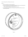
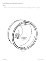
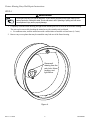
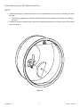
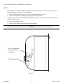
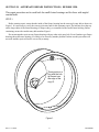
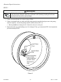
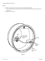
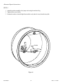
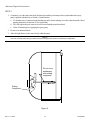
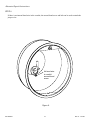
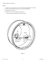
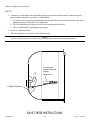
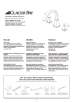
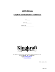
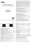
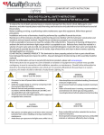
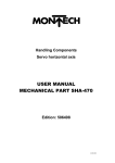
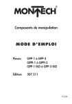
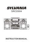
Hydrel Fixture Housing Rust Staining Repair Instructions
IMPORTANT SAFETY INSTRUCTIONS
READ AND FOLLOW ALL INSTRUCTIONS
SAVE THESE INSTRUCTIONS
Contents
SECTION I.
FIXTURE HOUSING ENTRY HUB REPAIR INSTRUCTIONS. . . . . . . . . . . . . . . . . . . . . . . . . . . . . . . 2
SECTION II.
ALTERNATE REPAIR INSTRUCTIONS, BEFORE 1998. . . . . . . . . . . . . . . . . . . . . . . . . . . . . . . . . . 9
WARNING
Before installing this product, read and follow all warning notices and instructions accompanying this product.
Failure to follow safety warnings and instructions can result in severe injury, death, or property damage. Call
(800) 831-7133 for additional free copies of these instructions.
Important Notice
Attention Installer.
This manual contains important information about the installation, operation and safe use of
this product. This information should be given to the owner/operator of this equipment.
DANGER
Risk of Electrical Shock or Electrocution.
Always disconnect power to the pool light at the circuit breaker before servicing the light. Failure to
do so could result in death or serious injury to installer, serviceman, pool users or others due to
electrical shock.
WARNING
Never operate this underwater light for more than 10 seconds unless it is totally submerged in water. Without total
submersion, the light assembly will get extremely hot, which may result in serious burns or in breakage of the lamp or
lens. This may result in serious injury to pool users, installers, or bystanders, or in damage to property.
WARNING
Use only the special pilot screw provided with this underwater light. This screw mounts and electrically
grounds the housing securely to the mounting ring and wet fixture housing. Failure to use the screw
provided could create an electrical hazard which could result in death or serious injury to pool users,
installers or others due to electrical shock. This procedure can be performed with the water in the pool.
Pentair Water Pool and Spa™
1620 Hawkins Ave., Sanford, NC 27330 • (919) 556-8000
10951 West Los Angeles Ave., Moorpark, CA 93021 • (805) 553-5000
Rev. A 1-18-06
1
P/N 620001
SECTION I.
FIXTURE HOUSING ENTRY HUB REPAIR INSTRUCTIONS.
STEP 1
Before starting repair, ensure that the inside of the fixture housing has the same style entry hub as shown in
Figure 1. It is necessary to verify the correct style entry hub for this warranty repair. The hub may be at the top
on the large radius of the fixture housing (45 degree entry), or assembled to the small fixture housing. Before
continuing, ensure the conduit entry hub matches Figure 1.
Do not attempt the repair on any fixture housing with any other style entry hub. Even if another type fixture
housing shows the same staining, it is likely to be caused by another problem. In that case this procedure will
not work and the repair will not be covered by warranty.
Three posts on a
ring with the hub
lip formed over
the edge of the
ring I.D.
hn-01-11-16-98
Figure 1.
P/N 620001
2
Rev. A 1-18-06
Fixture Housing Entry Hub Repair Instructions.
STEP 2
1. If there is no internal bond wire as shown, skip to STEP 3.
2. If there is an internal bond wire or a non-listed potting material around the bond post, remove the potting material
completely. A non-listed potting material would be silicone, RTV, etc.
a. Be very careful not to damage the No. 8 bond wire, the screw or the post.
3. Replace the bond wire or the bonding screw if it is damaged. Then go to instruction STEP 4 and complete the
procedures through STEP 6.
Light Fixture
Cord
Internal Bond
Wire
Remove bonding
lug potting
material if
present, check
that screw is
tight.
hn-02-11-16-98
Fixture 2.
Rev. A 1-18-06
3
P/N 620001
Fixture Housing Entry Hub Repair Instructions.
STEP 3
If there is no internal bond wire in the conduit, the fixture housing will appear as shown in Figure 3.
No bond wire
in conduit
unused bond
screw.
hn-03-11-16-98
Figure 3.
P/N 620001
4
Rev. A 1-18-06
Fixture Housing Entry Hub Repair Instructions.
STEP 4
WARNING
Working with muriatic acid can be dangerous. When cleaning elements always wear rubber gloves
and eye protection. Add acid to water, do not add water to acid. Splashing or spilling acid can cause
severe personal injury and/or property damage.
1. Completely clean the fixture housing, the light fixture and the pool wall of all of the brown/black staining.
The stain can be removed by brushing the stained area with a stainles steel pool brush.
a. For stubborn stains, treat the stained area with a mild solution of muriatic acid and water (1:5 ratio).
2. Remove any excess plaster that may be around the entry hub area of the fixture housing.
Remove all
staining from the
entry hub, fixture
housing, and
light fixture.
hn-01-11-16-98
Figure 4.
Rev. A 1-18-06
5
P/N 620001
Fixture Housing Entry Hub Repair Instructions.
STEP 5.
1. Attach an anode block, (with an allen head set screw), installed directly to one of the two unused posts on the
hub ring.
a. This is done by pushing the center hole of the block firmly and completely over the post, press-fitting it
into place.
2. Position the anode to clear the fixture cord with its rounded edge pointed away from the center of the conduit
entry, see Figure 5.
hn-04-11-16-98
Figure 5.
P/N 620001
6
Rev. A 1-18-06
Fixture Housing Entry Hub Repair Instructions.
STEP 6.
1. After fully pressing the anode block into place, tighten the set screw with a 3/32 inch allen wrench,
see Figure 6.
a. The allen wrench is not supplied with the kit.
Set Screw
hn-05-11-16-98
Figure 6.
Rev. A 1-18-06
7
P/N 620001
Fixture Housing Entry Hub Repair Instructions.
STEP 7
1. If a bonding wire is connected to the bonding lug in the fixture housing cover this connection with a listed
potting compound, (Scotchcast 2134 or equivelant).
a. This will require the pool water level to be lowered and the potted area dried.
b. Allow 30 minutes prior to applying the epoxy putty; see item 2, below.
2. Completely cover the exposed entry hub with two parts of underwater epoxy putty, (supplied with this kit), to
at least 1/4 inch thickness.
a. Do not cover the anode block.
b. Allow the light fixture cord to move freely within the putty.
NOTE
Cord must move freely within the putty to allow the removal of the light fixture should it ever need repair or replacement.
Do not cover anode
block with potting
compound.
Potting Compound
hn-06-11-16-98
Figure 7.
P/N 620001
8
Rev. A 1-18-06
SECTION II. ALTERNATE REPAIR INSTRUCTIONS, BEFORE 1998.
This repair procedure can be used both for small fixture housings and for those with angled
conduit hubs.
STEP 1.
Before starting repair, ensure that the inside of the fixture housing has the same style entry hub as shown in
Figure 1. It is necessary to verify the correct style entry hub for this warranty repair. The hub may be at the top
on the large radius of the fixture housing (45 degree entry), or assembled to the small fixture housing. Before
continuing, ensure the conduit entry hub matches Figure 1.
Do not attempt the repair on any fixture housing with any other style entry hub. Even if another type fixture
housing shows the same staining, it is likely to be caused by another problem. In that case this procedure will
not work and the repair will not be covered by warranty.
Three posts on a
ring with the hub
lip formed over
the edge of the
ring I.D.
hn-01-11-16-98
Figure 1.
Rev. A 1-18-06
9
P/N 620001
Alternate Repair Instructions
STEP 2
WARNING
Working with muriatic acid can be dangerous. When cleaning elements always wear rubber gloves
and eye protection. Add acid to water, do not add water to acid. Splashing or spilling acid can cause
severe personal injury and/or property damage.
1. If there is no internal bond wire as shown, skip to STEP 6.
2. If there is an internal bond wire with a non-listed potting material around the bond post, remove the potting
material completely. A non-listed potting material would be silicone, RTV, etc.
a. Be very careful not to damage the No. 8 bond wire, the screw or the post.
3. Replace the bond wire or the bonding screw if it is damaged. Then, go to instruction STEP 3 and complete the
procedures through STEP 5.
Light Fixture
Cord
Internal Bond
Wire
Remove bonding
lug non-listed
potting material if
present, check
that screw is
tight.
hn-02-11-16-98
Fixture 2.
P/N 620001
10
Rev. A 1-18-06
Alternate Repair Instructions
STEP 3
1. Attach No. 8 copper jumper wire to one of the two unused posts on the hub ring.
a. Place the ring over the post, and press the jumper wire in the gap between the ring and post opposite the
ring set screw.
2. Tighten the set screw firmly.
Post clamp
ring and set
screw
Anode
#10
Stainless
Screw
Copper
Mechanical
Lug
hn-07-11-16-98
Figure 3.
Rev. A 1-18-06
11
P/N 620001
Alternate Repair Instructions
STEP 4
1. Attach the anode asssembly to the jumper wire using the mechnical lug.
2. Tighten all the screws firmly.
3. Position the anode to clear the light fixture and the cord, and to be away from the entry hub.
Anode
hn-08-11-16-98
Figure 4.
P/N 620001
12
Rev. A 1-18-06
Alternate Repair Instructions
STEP 5
1. Completely cover the entire entry hub, the bond wire and the post clamp with two parts underwater epoxy
putty, (supplied with this kit), to at least 1/4 inch thickness.
a. If a bonding wire is connected to the bonding lug in the fixture housing cover this connection with a listed
potting compound, (Scotchcast 2134 or equivelant).
b. This will require the pool water level to be lowered and the potted area dried.
c. Allow 30 minutes prior to applying the epoxy putty.
2. Do not cover the anode block.
3. Allow the light fixture cord to move freely within the putty.
NOTE
Cord must move freely within the putty to allow the removal of the light fixture should it ever need repair or replacement.
Do not cover
anode assy.
with potting
compound
Potting
Compound
hn-09-11-16-98
Figure 5.
Rev. A 1-18-06
13
P/N 620001
Alternate Repair Instructions
STEP 6
If there is no internal bond wire in the conduit, the unused bond screw and hub can be used to attach the
jumper wire.
No bond wire
in conduit
unused bond
screw
hn-03-11-16-98
Figure 6.
P/N 620001
14
Rev. A 1-18-06
Alternate Repair Instructions
STEP 7
1.
2.
3.
4.
Attach the No. 8 copper jumper wire to the unused bond lug and tighten the screw frimly.
Attach the anode assembly to the jumper wire using the mechanical lug.
Tighten all the screws firmly.
Position the anode to clear the light fixture and the cord.
a. Ensure the anode is positioned away from the entry hub.
Anode
Jumper wire #8
copper bare
Copper Mechanical
Lug
hn-10-11-16-98
Figure 7.
Rev. A 1-18-06
15
P/N 620001
Alternate Repair Instructions
STEP 8
1. Completely cover the entire entry hub and the jumper wire connection with two parts of underwater epoxy
putty, (supplied with this kit), to at least 1/4 inch thickness.
a. If a jumper wire is connected to the bonding lug in the fixture housing cover this connection with a listed
potting compound, (Scotchcast 2134 or equivelant).
b. This will require the pool water level to be lowered and the potted area dried.
c. Allow 30 minutes prior to applying the epoxy putty.
2. Do not cover the anode block.
3. Allow the light fixture cord to move freely within the putty.
NOTE
Cord must move freely within the putty to allow the removal of the light fdixture should it ever need repair or replacement.
Do not cover
anode block with
potting
compound.
Potting Compound
hn-11-11-16-98
SAVE THESE INSTRUCTIONS.
P/N 620001
16
Rev. A 1-18-06