1
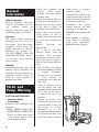
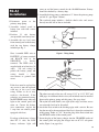
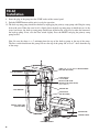
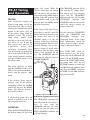
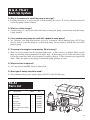
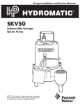
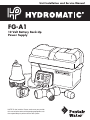
Unit Installation and Service Manual
FG-A1
12 Volt Battery Back-Up
Power Supply
NOTE! To the installer: Please make sure you provide
this manual to the owner of the pumping equipment or to
the responsible party who maintains the system.
General
Information
Before Operation:
Read the following instructions
carefully. Reasonable care and
safe
methods
should
be
practiced. Check local codes and
requirements before installation.
Attention:
This manual contains important
information for the safe use of
this product. Read this manual
completely before using this
product and refer to it often for
continued safe product use.
DO NOT THROW AWAY OR
LOSE THIS MANUAL. Keep it
in a safe place so that you may
refer to it often.
Warning:
Before handling these pumps and
controls, always disconnect the
power first. Do not smoke or use
sparkable electrical devices or
flames in a septic (gaseous) or
possible septic sump.
FG-A1 and
Pump Warning
CAUTION AND WARNING
Important Safety
Instructions
Rules for Safe Installation and
Operation
1. READ THESE RULES AND
INSTRUCTIONS CAREFULLY.
Failure to follow them could
cause serious bodily injury
and/or property damage.
2
2. Check local plumbing and
electrical
codes
before
installing. You must comply
with those rules.
3. Battery box must be kept in a
cool, dry, well ventilated area.
4. Battery must not be exposed
to any sparks or flames. An
explosion or fire could result.
5. Battery acid is very corrosive;
avoid spilling on skin or
clothing. Eye protection must
be worn when handling the
battery.
6. Battery
Selection
and
Maintenance
Use a new 12 volt, fully
charged battery with top
terminals. For maximum
performance and battery life, a
deep cycle (marine, group 24,
min. 105 AH) battery should be
used.
• The electrolyte level should
be checked monthly and filled
as required. Automotive
batteries may be used but
a
slight
decrease
in
performance and battery life
will result.
• Group 24 batteries will fit
into the battery box with
maximum battery dimensions
of 12" long x 6-1/2" wide x
9" high to the top of the
terminals.
• Replace the battery if the
back-up pump operated for an
extended period of time and
the battery is severely
discharged. It is also
recommended that the battery
be replaced every three years
even if the system is not used.
7. When service is required,
proceed carefully:
Disconnect the power at the
main electrical service box by
turning the circuit breaker off
or by removing the fuse.
Disconnect
the
battery
charger from the wall after
the power is disconnected.
DO NOT lift the pump by the
cord.
8. To be used only as a back-up
sump pump in residential
waste water applications.
DO NOT run the pump dry.
FG-A1
Installation
1. Disconnect power to the
primary sump pump.
2. Assemble control panel to
battery box with four screws
included.
3. Position 12 volt battery
(not provided) into battery box.
4. Assemble the two lead wires
from control panel to the battery
with the two battery clamps
included per Fig. 2.
Note: Assemble RED wire to
POSITIVE (+) battery terminal
and BLACK wire to the
NEGATIVE
(–)
battery
terminal. The RED wire is
supplied with an in-line fuse (10
amps, 250 volt rating) to
protect the battery, pump and
wiring
should
a
short,
over-current or ground fault
occur.
If this fuse must be replaced for
any reason, it must be replaced
with one of the exact same
rating. Failure to do so may
result in a fire hazard. If the
polarities are connected wrong,
the REVERSE battery indicator
light on the control panel will
come on. Correct the battery
wire connections (replace the
1 amp fuse on control panels
equipped with fuse).
If voltage of the battery is lower
than DC 11 volts, the LOW
battery indicator light will
come on and the buzzer sounds for the ALARM function. Battery
should be checked by a battery shop.
5. Assemble back-up pump a minimum of 1" above the primary pump
and tilt 30° (per Figure 1 below).
The enclosed pump includes a built-in check valve and screws
directly into the side of the tee included.
Tee Fitting
30º
Back-Up Sump Pump
Figure 1 Tilting Pump
Bolt
Ring Terminal
Battery Post
Battery Clamp
Figure 2 Attaching Ring Terminals and Battery Clamps
The other two ends of the tee will accept 1-1/4" or 1-1/2" PVC and
ABS pipe. An additional check valve (not included) must be installed
between the primary pump and this pump. (See page four.)
The nylon belt with buckle, two rigid nylon straps and four screws
are not needed and can be discarded.
6. Attach the float switch to the discharge pipe with a wire tie. Be sure
that the turn off or down position of the float is above the suction inlet
of this pump. Tether at 1-1/4." Insert the plug of the float switch into
the SENSOR socket of the control panel.
7. Insert the plug of the battery charger into the CHARGER socket of
the control panel and plug the charger into an AC-115 volt power
outlet (Figure 3 on page five).
3
FG-A1
Installation
8. Insert the plug of the pump into the PUMP socket of the control panel.
9. Push the RESET button and the unit is ready for operation.
10. The back-up sump pump should be checked by unplugging the primary sump pump and filling the sump
basin with water. When the water level is slightly above the back-up sump pump it should turn on. As the
water level drops, the back-up sump pump should turn off before the water level reaches the bottom of
the back-up pump. If not, raise the float switch slightly. Press the RESET and plug the primary sump
pump back in.
Note: Be sure that there is a 4" minimum from the top of the back-up pump to the top of the sump.
The float switch should turn this pump ON near the top of the pump and at least 2" down from the top
of the sump.
RIGID 1-1/4" or 1-1/2" PVC or ABS DISCHARGE
PIPE (NOT INCLUDED)
4 INCHES MINIMUM
FLOAT SWITCH
1-1/4" TETHER
BACK-UP SUMP PUMP
(WITH BUILT-IN CHECK VALVE)
(TILT PUMP 30°)
TEE ADAPTER
1 INCH MINIMUM
CHECK VALVE
(NOT INCLUDED)
PRIMARY SUMP PUMP
(NOT INCLUDED)
BATTERY BOX
SUMP BASIN
BATTERY CHARGER
4
CONTROL PANEL
FG-A1 Testing
and Operation
TESTING
After installation, unplug the
primary sump pump and fill the
sump with water. This is actually
imitating the condition that would
happen if the power went off
or the primary pump failed for
whatever reason. The back-up
sump pump should begin
operation as the water level rises
just above it’s top. If not, the
float sensor may need to be
re-positioned,
review
float
installation instructions. Even
after the back-up has pumped the
excess water out and shut off, the
alarm should continue sounding
until the ALARM switch is set to
the OFF position.
buzzer will sound. When the
FLOAT switch turns the backup
OFF, the buzzer will continue to
sound until the ALARM switch is
pushed to the OFF position. Push
the ALARM switch to the ON
position. Press the RESET button
for normal operation.
If the voltage of the battery drops
lower than 11 volts DC, the LOW
battery indicator will come on and
the buzzer will sound if the
ALARM switch is in the ON
position. At this time, the battery
should be checked and serviced or
replaced. The only “real” test for a
battery is when it is tested with a
load meter. Take the battery back
where it was purchased for the
test. The CHARGING indicator
will come ON when the battery is
UNDERCHARGED.
The alarm continues to sound
until the ALARM switch is set to
OFF to alert you that something is
wrong with the primary sump
pump.
The CHARGED indicator will be
ON until the DC voltage drops.
The battery will start charging
again and the CHARGING
indicator will come ON. If either
CHARGING
indicator
and
CHARGED indicator are not ON,
check the charger adapter for
proper connection.
Near the end of the CHARGING
cycle, the CHARGING and
CHARGED indicators may
alternately blink. If the lights
blink continuously, check the
battery leads for proper polarity
(Step 4) and replace the fuse.
Press PUMP TEST switch for
pump function test: the pump
comes ON and ALARM indicator
comes ON and BUZZER sounds.
Release the PUMP TEST switch,
the pump turns OFF but the
BUZZER continues to sound and
ALARM indicator continues to be
ON. Press the RESET switch, the
BUZZER and ALARM indicator
light will turn OFF.
If the back-up pump operates
properly, plug in the primary
sump pump and set the ALARM
switch ON and press the RESET
button. The back-up system is
now in full readiness.
If the back-up pump does not
operate as specified, refer to the
most asked questions list.
OPERATION
When the FLOAT SWITCH turns
the back-up pump ON, the alarm
Figure 3 AC-115 V Outlet and
Hydromatic piggyback switch plug
The CHARGING indicator will
turn OFF when the DC voltage is
over 13 volts, then the
CHARGED indicator will come
ON. At this time the battery is at
FULL-CHARGED condition and
will stop charging.
5
Q & A FG-A1
Backup System
Q. The red and yellow LED’s
flash on my control panel.
What’s wrong?
A. Maybe nothing at all! A slow
flash rate, (about 1 second, or
less), indicates that the charging
system has nearly charged the
battery to its optimum charge
level. The flashing LED’s should
slow and eventually stop when
the battery is completely charged.
A fast LED flash rate (more than
2 per second) indicated the 1 A
charging fuse has blown, the
battery leads are reversed or the
wall transformer is not supplying
proper voltage to the control box.
Check the battery connections,
then replace the fuse. If the LED’s
continue to fast flash, check the
115V outlet for proper current
and replace the plug-in wall
transformer, if necessary. A
severely discharged battery may
also cause a surge in the system
and blow the fuse if connected.
Q. When I hooked up the
system, the yellow charging
light came on. Why? The
battery was supposed to be
fully charged when I got it.
A. A new battery, although charged
adequately to start most engines,
will not be charged to its full/
optimum level. The charging
system supplied with your pump
monitors the charge level and
slowly charges the battery to its
optimum level.
Q. OK, after 2 days, the LED’s
are
blinking
between
“charged and charging.”
What’s wrong now?
A. Probably nothing; see question 2
above. The system normally takes
2–3 days to fully charge a good
battery from about 11.9 VDC to
14.4 VDC. As the battery
approaches full charge, the
6
LED’s will alternate between
“CHARGED” & “CHARGING.”
Q. Finally, the LED’s quit
alternating
and
the
“CHARGED” LED came on,
but every once in a while the
“CHARGING” LED comes on
for just a second or two,
then goes out. Is my system
OK?
A. Yes! No need to worry. It is
normal for a battery to lose some
of its charge (decay) when idle.
Our charging system monitors the
charge state and turns itself on to
boost the battery backup to its
optimum charge. This usually
takes from a few seconds to a few
minutes.
Q. We came home late one
evening and heard our
battery
backup
alarm
sounding. The pump wasn’t
running. What’s wrong?
A. It is possible that the primary
pump failed to operate when
needed and your backup pump
activated and drained the tank.
The alarm activates any time the
pump is called to operate.
It continues to operate until the
alarm condition is manually
acknowledged by pressing the
reset switch.
Q. Pressing the reset switch
didn’t silence the alarm.
Now what?
A. The alarm circuit is activated
so long as the float switch is
activated. Check to see if the
backup float switch is tangled or
caught in the sump or piping.
Remember to disconnect all
power before servicing.
Q. The float wasn't tangled, but
the alarm continues to
pulsate.
A. A pulsating alarm is different
from a steady tone. The pulsing
alarm indicated that the battery
voltage has dipped below an
acceptable level. As a precaution,
the charging circuit is locked out
when this occurs, just in case one
or more cells have shorted. It will
be necessary to remove the
battery and have it charged on
a commercial automotive or
marine battery charger, per the
manufacturer’s instructions. Once
the battery voltage can be
sustained above 11.9 VDC, the
battery can be reinstalled in the
system and the on-board charging
circuit can again be used to
maintain the battery charge.
Q. When I got my system home
and prepared to install it,
I found out that the pump
cable, sensor and charging
cord were too short to reach
the control box. Can I splice
the leads so that they will
reach?
A. No! The cable lengths were
all designed around optimum
operating parameters and are at a
maximum length for their given
sizes. Since the charger and pump
are microprocessor (computer)
controlled, changing the cable
lengths may affect critical
computer inputs which could
cause the system to malfunction
and may even present a fire
hazard.
Q. I couldn’t install my battery
backup pump above my
primary pump per your
instructions, because my
sump is too shallow. Will it
matter if it is installed
BESIDE my primary pump?
A. Yes. Installing a backup pump in
the sump beside the primary
pump could spell disaster.
Sediment will accumulate inside
the backup pump and may cause
it to fail when needed most. The
backup pump must be installed
above the normal turn-on level of
the primary pump. You may need
to modify or replace your sump if
it is too small. A minimum 30"
deep sump is recommended.
Remember, the backup pump
must also be tilted at a 30 degree
angle to operate properly. (It may
air bind if not tilted.)
Q & A FG-A1
Back-Up System
Q. Why is it necessary to install the pump at an angle?
A. Installing the pump at an angle prevents air from entering the system. If air were allowed to enter the
system, the pump would not operate.
Q. What is a trickle charger?
A. A trickle charger is a device that allows the battery to charge the pump system constant until the battery
is fully charged.
Q. Can a backup sump pump be used with a pedestal sump pump?
A. Yes. However, your sump basin must be at least 18" in diameter, and an additional piece of PVC pipe
must be used to extend the pump tee so the backup pump will not interfere with the float rod of the
pedestal pump.
Q. The pump is buzzing but not pumping. What's wrong?
A. There are several reasons why this situation might occur: A) The system is air locked. Make sure the
pump is positioned at the recommended 30 degree angle. B) Your battery is low. If the low-battery light
is lit on the control box, make sure your battery is properly charged. C) The system may be clogged with
debris. Make sure pipes are not plugged, and that the pump openings are clear.
Q. What size fuse is required?
A. A 12 amp fuse for the RED (Positive) battery lead.
Q. What type of battery should be used?
A. We recommend a deep cycle (marine) battery 650 CCA with 105 AH rating.
FG-A1
Parts List
Ref.
No.
1
2
3
4
5
6
7
Description
Sump Pump
Battery Box
Panel Control
Tee Adapter
Battery Charger
Level Control
Battery Cable Clamp Assembly
Not Shown
2
Qty.
Req’d.
1
1
1
1
1
1
1
Part
No.
149530001
149530041
149530031
149530011
149530061
149530021
149530051
1
3
5
6
4
7
WARRANTY
Hydromatic® warrants to the original purchaser of each Hydromatic product(s) that any part
thereof that proves to be defective in material or workmanship within one year from date of installation or
18 months from manufacture date, whichever comes first, will be replaced at no charge with a new or
remanufactured part, F.O.B. factory. Purchaser shall assume all responsibility and expense from removal,
reinstallation and freight. Any item(s) designated as manufactured by others shall be covered only by the
express warranty of the manufacturer thereof. This warranty does not apply to damage resulting from
accident, alteration, design, misuse or abuse. The pump must be installed, operated and maintained in
accordance with the published instructions of the appropriate Installation & Service Manual.
All dual seal non-clogs and 3–5 HP grinders must have seal failure and heat sensors attached and functional
for Warranty to be in effect. If a seal failure should occur, Hydromatic will cover only the lower seal and labor
thereof. Labor is based on Authorized Service Center contract allowance. If the heat sensor is not attached
and functional, Warranty is void. If the seal failure sensor is not attached and functional, Warranty is void.
If the material furnished to the Buyer shall fail to conform to this contract or to any of the terms of this
written warranty, Hydromatic shall replace such nonconforming material at the original point
of delivery and shall furnish instruction for its disposition. Any transportation charges involved in such
disposition shall be for the Buyer’s account. The Buyer’s exclusive and sole remedy on account or in respect
of the furnishing of material that does not conform to this contract or to this written warranty, shall be to
secure replacement thereof as aforesaid. Hydromatic shall not in any event be liable for the cost of any labor
expended on any such material or for any incidental or consequential damages to anyone by
reason of the fact that such material does not conform to this contract or to this written warranty.
ALL IMPLIED WARRANTIES, INCLUDING THE IMPLIED WARRANTY OF MERCHANTABILITY
AND THE IMPLIED WARRANTY OF FITNESS FOR A PARTICULAR PURPOSE, ARE DISCLAIMED
TO THE SAME EXTENT AS THE EXPRESS WARRANTY CONTAINED HEREIN. Some states do not
allow limitations on how long an implied warranty lasts, so the above limitation may not apply to you.
MANUFACTURER EXPRESSLY DISCLAIMS AND EXCLUDES ANY LIABILITY FOR
CONSEQUENTIAL OR INCIDENTAL DAMAGES FOR BREACH OF ANY EXPRESS OR IMPLIED
WARRANTY ARISING IN CONNECTION WITH THIS PRODUCT, INCLUDING WITHOUT
LIMITATION, WHETHER IN TORT, NEGLIGENCE, STRICT LIABILITY CONTRACT OR
OTHERWISE. Some states do not allow the exclusion or limitation of incidental or consequential damages,
so the above limitation or exclusion may not apply to you. This warranty gives you specific legal rights, and
you may also have other rights which vary from state to state.
– Your Authorized Local Distributor –
USA
740 East 9th Street, Ashland, Ohio 44805
Tel: 419-289-3042 Fax: 419-281-4087
www.hydromatic.com
© 2007 Hydromatic Ashland, Ohio. All Rights Reserved.
®
CANADA
269 Trillium Drive, Kitchener, Ontario, Canada N2G 4W5
Tel: 519-896-2163 Fax: 519-896-6337
Part # 5625-435-1
Item # W-03-435 6/07