1
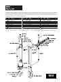
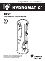
Pump Installation and Service Manual
TRST
LOW PRESSURE SEWAGE SYSTEM
R
LISTED
NOTE! To the installer: Please make sure you provide
this manual to the owner of the pumping equipment or to
the responsible party who maintains the system.
General
Information
Thank you for purchasing your
Hydromatic® pump. To help
ensure years of trouble-free
operation, please read the
following manual carefully.
Before Operation:
Read the following instructions
carefully. Reasonable care and
safe methods should be practiced.
Check
local
codes
and
requirements before installation.
Attention:
This manual contains important
information for the safe use of
this product. Read this manual
completely before using this
product and refer to it often for
continued safe product use.
DO NOT THROW AWAY OR
LOSE THIS MANUAL. Keep it
in a safe place so that you may
refer to it often.
Unpacking Pump:
Remove pump from carton. When
unpacking unit, check for
concealed damage. Claims for
damage must be made at the
receiving end through the delivery
carrier. Damage cannot be
processed from the factory.
WARNING: Before handling
these pumps and controls,
always disconnect the power
first. Do not smoke or use
sparkable electrical devices or
flames in a septic (gaseous) or
possible septic sump.
2
Systems Description:
Two basic models of the
Hydromatic
TRST
grinder
systems are covered by these
instructions:
1. FBTRSTSG Factory built
TRST
simplex
system
utilizing a fiberglass basin.
2. FBTRSTDG Factory built
TRST duplex system utilizing
a fiberglass basin.
Factory built fiberglass basin
systems
are
available
in
24" minimum diameter basins
for simplex systems and 36"
minimum diameter basins for
duplex systems.
In a TRST system, the pump is
raised and lowered in the basin
while being guided by a fiberglass
guide rail. A hydraulic sealing
flange at the pump discharge
allows the pump to be removed
without disconnecting piping or
electrical connections.
Application:
These pump systems are basically
designed for pumping sewage
water with a pH ranging from 5 to
9, specific gravities from 0.9 to
1.1, viscosities ranging from 28 to
35 S.S.U. and temperatures up
to 140˚ F.
WARNING: Pump is not to be
installed in locations considered
hazardous in accordance with
the National Electric Code
ANSI/NFPA 70.
Pump Models:
The TRST rail system may
employ any UL approved
Hydromatic 2 HP submersible
grinder pump which utilizes cutter
blades to grind solids into a slurry.
Refer to the pump service manual
for all Hydromatic pumps when
adjusting, dismantling, or repairing
the pump.
Inspection:
Check to be sure that all items for
your particular system are included.
Check that the phase and voltage on
the pump nameplate are correct as
ordered and match available job
site voltage.
Codes:
WARNING: To reduce the risk
of electric shock, electric
installations
shall
be
in
accordance with the National
Electric Code and all applicable
local codes and ordinances.
Consult the local inspector(s)
before installation to avoid costly
delays or rework.
Excavation Location:
Excavation location shall be
made according to local codes and
regulations. Care should be taken
to avoid buried utility lines
piping, and other buried structures
and foundations.
Pump
Installation
Installation Skill Requirements:
The installation of a TRST basin
system is a specialized skill, which
requires individuals with a basic
understanding of excavating, pipe
fitting, and electrical wiring.
Hydromatic
cannot
assume
responsibility
for
problems
or damage resulting from
inexperienced or undersupervised
laborers. These instructions are
meant only to be an installation
guide; therefore, installation
conditions not covered in these
instructions rely on the experience
and mechanical aptitude of those
installing the system.
Grinder Pump Attachments:
Step 1
Attach the stainless steel foot
bracket to bottom of the pump
with two bolts and lock washers
provided. See Figure 1.
Step 2
Apply pipe thread sealant to
discharge piping threads and screw
assembly into the pump discharge.
For vertical pump discharge
systems, tighten piping until a
measurable distance of 23-3/4"
±1/8" from the floor to the center
of the ball check valve discharge
diaphragm hole is achieved.
See Figure 2.
23-5/8"
to
23-7/8"
Figure 2
Step 3
Install the stainless steel lifting
bail to pump with two bolts
and two lock washers provided.
Position the lifting bail with
mounting tabs directed toward the
ball check valve as shown.
See Figure 3.
Step 4
Attach lifting chain, cable or rope
as supplied to the lifting bail
shackle. Tighten threaded shackle
pin with pliers.
WARNING: To reduce risk of
electric shock, do not connect
conduit to pump.
Excavation :
Step 1
Determine appropriate excavation
based on size of the basin, desired
entrance point of the influent line,
and entrance of power connection.
Step 2
Obtain proper backfill material.
The backfill material provides
as much as 90% of the basin’s
support under certain stress
conditions. The installer must be
positive that correct bed and
backfill materials are utilized per
instructions as follows:
A. Clean and free flowing gravel
with particle size not less than
1/8" nor more than 3/4" in
diameter. Use this description
when ordering or specifying
as material varies upon
geographical location. This
material is commonly known
as “pea gravel”.
B. Stone or gravel crushings with
angular particle size of not
less than 1/8", no more than
1/2" diameter, washed and
free flowing, is acceptable as
an alternative material.
CAUTION:
In
freezing
conditions the backfill must be
dry and free of ice. Do not use
other backfill materials. The
basin warranty is automatically
void if materials other than the
recommended bed and backfill
materials are used.
Figure 1
Figure 3
3
Pump
Installation
Step 3
The entire periphery, including
under the basin, requires 4 to 6"
of appropriate fill. The ideal basin
pad is concrete in conjunction
with anti-flotation tie-down studs.
Basin anti-flotation tie-down kits
are available from Hydromatic. If
concrete pad is not used, the
aggregate must be compacted to
85% standard proctor density.
Concrete pad or aggregate
surface must be leveled flat and
free of voids to conform to the
basin bottom. Basin bedding
depth should be calculated such
that the basin top will protrude 3"
above the normal grade upon
final installation.
CAUTION: If the basin is not
tied down during installation,
rain or flood conditions may
cause the basin to float upward,
causing damage to the basin or
basin connections. Claims for
this type of damage cannot be
processed by Hydromatic.
Basin System Handling:
Factory built fiberglass basin
systems must not be dropped,
dragged, rolled, or handled
with sharp objects. Improper
handling of basins may result in
damage to the basin, damage to
basin components, or leaks in the
piping assemblies.
Basin Installation:
Step 1
Inspect the fiberglass guide rail to
ensure it is securely fastened to
the basin wall.
4
Step 2
An inlet grommet is the standard
supplied influent connection
device. If another type of inlet hub
is used, refer to the directions
included with the hub.
Inlet grommet: Determine point at
which influent line will enter basin
and, using a hole saw sized per
chart below, drill a hole through the
basin wall. Clean cut hole and apply
a sealant coating to the cut section to
prevent fiberglass deterioration.
Insert the inlet grommet into the
drilled hole.
Step 3
PIPE
SIZE
HOLE SAW
DIAMETER
4"
6"
5"
7"
Lifting of the basin may be
done with a nylon or other
non-damaging type material sling.
Do not wrap a chain or steel cable
around the basin as damage
may result. Do not attach lifting
mechanism around discharge
hub(s) or electrical hub.
Step 4
Lower the basin into excavation,
position and level properly.
Mount basin with base anchor bolts
if an anti-flotation tie-down kit is
used. Inspect fiberglass basin and
seal off any cuts or scratches to
prevent fiberglass deterioration.
Step 5
Lubricate inside lip of inlet
grommet with pipe soap. Clean
outer end of influent pipe
and push pipe through grommet.
Ensure pipe does not protrude
inside basin so as to interfere with
pump removal or float switch
operation.
Step 6
Close shut-off valve and make
discharge line connection. It is
recommended that an additional
shut-off valve and redundant check
valve, by installing contractor, be
located outside the basin. This can
be at any force main entrances - check
local codes for specific requirements.
Step 7
If system is supplied with a float
bracket, attach float switches to
the float bracket by clamping
strain relief bushings around the
float cords, then inserting and
twisting the bushings into the float
bracket slots.
Step 8
After grinder pump attachments
have been made, lower the pump
unit down the guide rail to ensure
the ball check valve’s sealing
flange aligns and connects
properly with discharge elbow.
WARNING: Grinder basin
systems must be vented in
accordance with local plumbing
codes. Do not remove the vent.
Pedestal Panel Mount
Systems Installation:
Step 1
Ensure power source is off
or disconnected.
Step 2
Place insulator strip or bushing
onto sump cover opening to protect
insulation on incoming cords.
Step 3
Insert all cords through the sump
cover opening and then up
through the pedestal. Mount the
pedestal on sump cover with vent
openings pointing downward.
Step 4
Route pump and control wires
through pedestal, sealing block
and panel. Mount sealing block
and panel to pedestal with
hardware provided. Ensure
pedestal gasket seals against
panel, and tighten all cord nuts
while leaving approximately 3" of
play in the cords from the tank.
IMPORTANT: Any unused
holes in the sealing block must
be plugged to prevent the
corrosive atmosphere of the
basin from entering the control
panel. Plug any unused hole(s)
with the nylon plug(s) provided.
Junction Box and Direct Burial
Cable Systems Installation:
Step 1
Ensure power source is off
or disconnected.
Step 2
Push pump power/seal failure/heat
sensor cord and float cords
through cord grips in the junction
box and tighten. To prevent
corrosion or electrical short, plug
any unused holes in junction box.
Step 3
Make all wiring connections
inside junction box for all
wires required to connect to the
control panel.
Step 4
Junction Box Conduit Systems:
It is recommended that the
customer furnish and install a
conduit seal outside the basin to
prevent surface water from
entering the junction box.
Direct Burial Cable:
Incoming burial cable(s) must be
fed through basin cord grip(s)
then tightened.
Control Panel Wiring:
WARNING: To reduce risk
of electric shock, electric
installations shall be in
accordance with the National
Electric Code and all applicable
local codes and ordinances.
Step 1
Ensure power source is off
or disconnected.
Step 2
Connect pump power, seal failure/
heat sensor, and float cords to
panel terminals per the schematic
provided with the control panel.
The white, black and red pump
power leads must be connected to
the proper terminals in the control
panel marked “W”, “BK” and “R”
or the pump will not operate. All
conduits and cables entering the
panel must be sealed.
NOTE:
A
Hydromatic
approved control panel must
be used or the pump warranty
is void.
WARNING: To reduce risk
of electric shock, pump is
provided with grounding wire.
Be certain that it is connected
to ground. Properly connect
the panel ground wire to a
grounding rod. Improper
grounding voids warranty.
WARNING: To reduce risk of
electric shock, connect heat
sensor leads to heat sensor
circuits. Motor protection must
be provided by the control
panel. See nameplate on the
pump for information necessary
for proper selection of motor
protection.
5
TYPICAL SIMPLEX – 230 VOLTS – SINGLE PHASE SCHEMATIC
NOTE: Use copper, 60˚C. wire insulation for all field wiring terminals.
WARNING: Disconnect power supply before servicing.
WARNING: Metal back panel is to be connected to a good ground in accordance with local electrical codes.
Figure 4
6
TYPICAL DUPLEX – 230 VOLTS – SINGLE PHASE SCHEMATIC
NOTE: Use copper, 60˚C. wire insulation for all field wiring terminals.
WARNING: Disconnect power supply before servicing.
WARNING: Metal back panel is to be connected to a good ground in accordance with local electrical codes.
Figure 5
7
Final Backfill for Fiberglass Basin Systems:
Refer to section “Excavation” for proper backfill materials. Ensure
backfill material is free of rocks, clods, and debris. See Figure 6.
Pump
Operations
CAUTION: In freezing conditions the backfill must be dry and free
of ice. Support for all piping and electrical lines must be provided
during backfilling.
Preoperation:
Step 1
Remove pump from basin.
At least a 4 - 6 inch wide band of compacted aggregate must be placed
in successive layers (6" lifts) around the entire periphery of the basin.
Carefully compact aggregate under all piping and electrical lines.
Cover grade should slope down 3" to the normal surrounding grade.
Care must be taken to prevent damage to any influent, discharge, or
electrical connections made to the basin.
WARNING: Hazardous moving
parts. To reduce the risk of
injury, disconnect power before
servicing pump.
4" to 6"
3"
12"
INLET
1-1/4"
DISCHARGE
BACKFILL
ANCHOR
BOLTS
Anti-Flotation
Flange Mounting
4" TO 6"
Figure 6
8
BEDDING
A Concrete Pad or Aggregate
Step 2
With power off, turn radial cutter
with a screwdriver to be sure
it rotates freely. If necessary
to adjust, refer to the pump
service manual.
Step 3
Stand clear from pump and with
power on, check for proper
operation of pump by turning
H-O-A
switch
to
Hand
momentarily and then Off.
IMPORTANT: Do not leave
pump in basin unless it is placed
in operation. If a pump has been
out of service for an extended
period of time, with the power
off, rotate the impeller by
turning the radial cutter with
a screwdriver to be sure it
rotates freely.
Start-up:
Step 1
Run clear water into the basin
until motor housing is covered.
Step 2
Open the shut-off valve to the
discharge line.
CAUTION:
Do
not
use
excessive force when operating
the shutoff valve or damage to
the valve or valve handle may
occur. The valve is closed when
a noticeable stop is felt upon
closing. The valve is completely
open upon 9 full counterclockwise
turns from the closed position.
Step 3
Check for proper voltage of
incoming power with a voltmeter.
Step 4
Ensure H-O-A switch is in
the Off position and turn on main
breaker.
Step 5
Start the pump by turning
the H-O-A switch to the Hand
position.
Step 6
Check the pump amperage
with clamp on ammeter on black
pump lead. Readings higher
than nameplate indicate clogged
pump, miswiring, or improper
voltage. If basin is not being
pumped down and amperage
readings are considerably lower
than nameplate, then the pump is
air locked.
NOTE: Nameplate amperage is
rated at the largest impeller
diameter trim. Pumps with
smaller diameter impellers will
draw slightly less amps than
nameplate. If pump is air
locked, refer to the trouble
check list section 4 in this
manual. If pump does not run,
check that the white, black and
red pump power leads are
properly connected to the
terminals in the control panel
marked “W”, “BK” and “R”.
Step 7
Float Adjustment for
Simplex Systems:
Adjust floats so that the pump
starts when the water level is just
above the pump motor housing,
and the pump shuts off when the
water level is 2 inches above the
pump volute discharge.
Float Adjustment for
Duplex Systems:
Adjust floats so the lead pump
will start when the water level is
just above the motor housing. The
lag pump start float should be 5
to 6 inches above the lead pump
start float. Adjust pump shut-off
so that water level is within 2
inches above pump volute
discharge. Pumps should alternate
starting, between each other,
upon successive pump-down
cycles. To check lag pump level,
set both H-O-A switches to Off
position and allow water to surpass
the lag pump level, then set both
H-O-A
switches
to
Auto
position and both pumps should
start. Turn off one pump and be
sure second pump starts when lag
pump level is reached on second
trial. If pumps fail to cycle in this
manner, retrace control float
wiring to panel.
Step 8
Ensure H-O-A switch(s) is set to
Auto when system is placed into
service.
Pump
Troubleshooting
WARNING: Hazardous moving
parts. To reduce risk of
injury, disconnect power before
servicing pump.
WARNING: To reduce risk
of electric shock, pump is
provided with grounding wire.
Be certain that it is connected
to ground.
WARNING: To reduce risk of
electric shock, do not remove
pump cord or strain relief.
The following list describes
possible problems and possible
solutions. Refer to the pump and
panel installation and service
manuals for details regarding any
necessary adjusting, dismantling or
repair work.
Pump Runs but Does Not
Pump Down the Basin with the
H-O-A Switch in Either Hand or
Automatic Position.
1. Cutters may be clogged.
An amperage higher than
the nameplate may indicate
this problem.
2. Discharge gate valve may
be closed.
3. Pump may be air locked.
Fill basin approximately 10
inches or more above the ball
check valve assembly. Raise
pump assembly so that the ball
check valve disengages the
discharge elbow (approximately
6 inches). Stand clear from the
sump opening to avoid
spray and turn pump on for a
brief second to clear trapped
air in the volute.
9
Pump
Troubleshooting
4. Clogging anywhere from
cutters
to check valve.
This is evident if no water
is discharged out of the check
valve after raising the pump to
disconnect the sealing flange.
Pull pump assembly and check
for cause of clogging.
5. Discharge head may be too
high. Check elevation against
design point of pump.
6. Clogging exists beyond the
sealing flange. This is evident if
water is discharged through the
check valve when raising the
pump from the disconnect sealing
flange. Inspect system basin
piping or discharge piping from
basin to locate clogging.
Basin Level Is Pumped Down
with H-O-A on Switch Hand
Position, but Is Not Pumped
Down with H-O-A Switch on
Automatic Position.
1. Floats are not hanging free
in the basin or are dirty.
Pump the level down with the
H-O-A switch on Hand, so that
the floats can be observed.
Relocate and clean float(s) as
necessary.
2. If this is a new installation and
original start-up, the floats may
be miswired into the control
panel. If the On and Off float
are reversed, the pump will
short cycle on and off and will
not pump the level down.
3. Floats or alternator are
malfunctioning. Pull the floats
out of the basin and hang the
Off and On floats from your
hand. Turn the H-O-A switch to
Auto. Tilt the Off float so that
the large end is above the cord
10
end – nothing should happen.
While keeping the Off float
tilted, tilt the On float in the
same manner – the pump should
come on. Suspend the On float
again from your hand – the
pump should continue to run.
Finally, suspend the Off float –
the pump should stop running.
If this procedure does not cause
the pump to operate as
described, either replace the
float(s) or replace the alternator
relay if the system is duplex.
Seal Failure Light Comes On.
This may indicate that the lower
seal has failed and has allowed
water to enter the seal housing
and made contact with the seal
failure probe. Or this may indicate
that a control circuit has become
grounded. Check out all control
circuit wiring for moisture. If
this is not the case, then the pump
must be pulled for maintenance.
Refer to pump installation and
service manual for replacing the
lower seal.
Pump Run Light Stays On.
1. H-O-A switch may be in Hand
position.
2. Lower float may have failed
causing
the
pump
to
continue operating below the
Off level.
3. Pump may be air locked.
4. Cutters may be clogged.
Circuit Breaker Trips When
Pump Tries To Start.
1. Short circuit in pump motor.
2. Water may have entered
the motor housing through
either worn-out mechanical
seals or O-rings.
3. Start component(s) failure.
Check start capacitor and start
relay for failure.
4. Pump may be miswired to
panel. Check to ensure the
white, black, and red pump
power leads are connected
correctly to panel.
Overload Trips, Is Manually
Reset, and Then Trips Again.
1. Cutters may be clogged. It
is possible that the pump
stalled during operation,
and starting and stopping
cleared the cutters. If resetting
the overloads solves this
problem, return the H-O-A
switch to Auto and observe
operation.
2. Pump motor may have failed.
3. Start component(s) failure.
Check start capacitor and start
relay for failure.
4. Pump may be miswired to
panel. Check to ensure the
white, black, and red pump
power leads are connected
correctly to panel.
TRST
Parts List
ORDERING REPLACEMENT PARTS: Product improvements are made from time to time. The latest part design will be furnished
as long as it is interchangeable with the old part.When ordering replacement parts, always furnish the following information: (1)
pump serial number, (2) pump model and size, (3) part description, (4) part number, (5) impeller diameter (if ordering impeller),
(6) quantity required, and (7) shipping instructions.
Ref.
No.
Part
No.
1
2
3
4
5
6
7
8
9
RTF
13712-001-3
156-023-1
101-022-1
12745-200-5
11945-000-1
176-005-1
177-004-1
13325-100-3
Part
Description
Pump
Pump Foot Bracket
Flat Washer
Screw
Ball Check Valve
Shackle
Screw
Lock Washer
*Guide Rail Clip
Qty.
Ref.
No.
Part
No.
1
1
1
2
1
1
2
2
1
10
11
12
13
14
15
16
17
18
14068-XXX-3
12720-101-1
12331-XXX-3
176-003-1
177-004-1
12777-200-5
150-051-1
150-052-1
13294-XXX-5
Part
Description
Rail Guide
Elbow
Pipe
Screw
Lock Washer
Shut-Off Valve
O-Ring
O-Ring
Valve Handle Extension
Qty.
1
1
1
6
6
1
1
1
1
Ref.
No.
Part
No.
19
*19
20
21
22
23
24
12746-211-5
12746-225-5
14116-004-3
13578-000-5
12726-001-1
14082-000-1
14079-000-1
Part
Description
Qty.
Pipe Assembly G1X/G1LX
Pipe Assembly HPG
Lifting Bail
*Riser Bracket
Discharge Hub
Seal Ring
Lock Nut
1
1
1
1
1
1
1
* Refer to factory for 30" diameter duplex systems. XXX Part number changes per tank depth.
Notes: S — Parts in Seal Kit C — Parts in Carbide Seal Kit I — Parts in Impeller Kit R — Parts in Rebuild Kit *Consult Factory
TRST
11
WARRANTY
Hydromatic® warrants to the original purchaser of each Hydromatic product(s) that any part
thereof that proves to be defective in material or workmanship within one year from date of installation or
18 months from manufacture date, whichever comes first, will be replaced at no charge with a new or
remanufactured part, F.O.B. factory. Purchaser shall assume all responsibility and expense from removal,
reinstallation and freight. Any item(s) designated as manufactured by others shall be covered only by the
express warranty of the manufacturer thereof. This warranty does not apply to damage resulting from
accident, alteration, design, misuse or abuse. The pump must be installed, operated and maintained in
accordance with the published instructions of the appropriate Installation & Service Manual.
All dual seal non-clogs and 3–5 HP grinders must have seal failure and heat sensors attached and functional
for Warranty to be in effect. If a seal failure should occur, Hydromatic will cover only the lower seal and labor
thereof. Labor is based on Authorized Service Center contract allowance. If the heat sensor is not attached
and functional, Warranty is void. If the seal failure sensor is not attached and functional, Warranty is void.
If the material furnished to the Buyer shall fail to conform to this contract or to any of the terms of this
written warranty, Hydromatic shall replace such nonconforming material at the original point
of delivery and shall furnish instruction for its disposition. Any transportation charges involved in such
disposition shall be for the Buyer’s account. The Buyer’s exclusive and sole remedy on account or in respect
of the furnishing of material that does not conform to this contract or to this written warranty, shall be to
secure replacement thereof as aforesaid. Hydromatic shall not in any event be liable for the cost of any labor
expended on any such material or for any incidental or consequential damages to anyone by
reason of the fact that such material does not conform to this contract or to this written warranty.
ALL IMPLIED WARRANTIES, INCLUDING THE IMPLIED WARRANTY OF MERCHANTABILITY
AND THE IMPLIED WARRANTY OF FITNESS FOR A PARTICULAR PURPOSE, ARE DISCLAIMED
TO THE SAME EXTENT AS THE EXPRESS WARRANTY CONTAINED HEREIN. Some states do not
allow limitations on how long an implied warranty lasts, so the above limitation may not apply to you.
MANUFACTURER EXPRESSLY DISCLAIMS AND EXCLUDES ANY LIABILITY FOR
CONSEQUENTIAL OR INCIDENTAL DAMAGES FOR BREACH OF ANY EXPRESS OR IMPLIED
WARRANTY ARISING IN CONNECTION WITH THIS PRODUCT, INCLUDING WITHOUT
LIMITATION, WHETHER IN TORT, NEGLIGENCE, STRICT LIABILITY CONTRACT OR
OTHERWISE. Some states do not allow the exclusion or limitation of incidental or consequential damages,
so the above limitation or exclusion may not apply to you. This warranty gives you specific legal rights, and
you may also have other rights which vary from state to state.
– Your Authorized Local Distributor –
USA
740 East 9th Street, Ashland, Ohio 44805
Tel: 419-289-3042 Fax: 419-281-4087
www.hydromatic.com
© 2006 Hydromatic Ashland, Ohio. All Rights Reserved.
®
CANADA
269 Trillium Drive, Kitchener, Ontario, Canada N2G 4W5
Tel: 519-896-2163 Fax: 519-896-6337
Part # 5625-381-1
Item # E-03-381 6/06