1
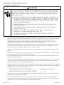
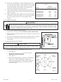
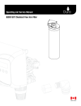
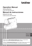
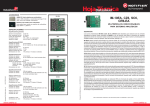
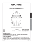
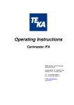
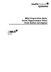
Rev. C 7-6-01
1
P/N 075122
3. The "SM/SMBW" Series Filter has been listed and
approved by the National Sanitation foundation. This
booklet will enable you to install and operate your pool
filter in the correct manner. Correct installation and
operation will result in the trouble free operation of a
quality product, as well as prevent unnecessary
repairs.
4. Model SMBW Filter System
U.S. Patent No.
4,414,109
4,328,833
a. Standard SM Series Filter with built-in backwash
valve. Simplifies plumbing installations.
5. Model SM Filter System
a. Standard SM Series requires separate valves for
backwash.
CAUTION
Before starting any filter system, be sure the pump has been adequately primed by filling the strainer on the pump with water.
Failure to do so will result in pump seal problems. When installing in conjunction with a heater, a one-way check valve
should be used between the filter and heater to prevent the backflow of hot water from damaging the filter internals.
B. WHAT IS DIATOMACEOUS EARTH AND HOW DOES IT FILTER WATER?
1. Diatomaceous earth is the skeletal remains of microscopic one-cell aquatic plants called diatoms, also known as
diatomite, D.E., and more properly diatomaceous earth.
2. Under the microscope, these minute diatoms show an amazingly intricate design and variety of forms, such as discshaped, boat-shaped, needle-like and many have a lace-like porous structure.
3. When used as a filter aid, the diatomaceous earth is mixed with water to form a slurry for filter 'precoat'. This
mixture is introduced into the filter system by means of a slurry pot, or by pouring directly into the surface skimmer
with the pump running. The minute diatoms are deposited on the outer surface of the filter elements, forming a
'strawpile' layer or cake by interlacing and overlapping, and thus providing countless microscopic channels which
entrap suspended impurities, but allow clear water to pass through without clogging.
4. We recommend the use of D.E. which is sold and labeled for use with swimming pools and spas. These grades of
D.E. typically have a median particle size of 34 microns, which is ideal for most applications.
WARNING
Failure to operate your filter system or inadequate filtration can cause poor water clarity obstruction visibility in your pool and can
allow diving in shallow pool area, or diving into or on top of obscured objects which can cause serious bodily injury or drowning.
Diatomaceous Earth (D.E.)
Precoat Requirements
C. FILTER PRECOATING INSTRUCTION:
1. Mix the Diatomaceous Earth in a pail of water to
form a slurry, then pour the mixture directly into the
surface skimmer with the pump running. Insure that
the right quantity of D.E. is used as shown in the
table.
*
P/N 075122
2
Filter Model
Number
*By Weight
Pounds
1018
1027
1036
1045
1054
2024
2036
2048
2060
2072
1.8
2.7
3.6
4.5
5.4
2.4
3.6
4.8
6.0
7.2
By Weight - 1 lb. of D.E. per 10 sq. ft. of filter surface area.
Rev. C 7-6-01
SECTION II. FILTER INSTALLATION.
A. GENERAL INFORMATION
WARNING
THIS FILTER OPERATES UNDER HIGH PRESSURE. WHEN ANY PART OF THE CIRCULATING SYSTEM,
e.g., CLAMP, PUMP, FILTER, VALVE(S), ETC. IS SERVICED, AIR CAN ENTER THE SYSTEM AND BECOME
PRESSURIZED. PRESSURIZED AIR CAN CAUSE THE LID TO BE BLOWN OFF WHICH CAN RESULT IN
SEVERE INJURY, DEATH, OR PROPERTY DAMAGE. TO AVOID THIS POTENTIAL HAZARD, FOLLOW
THESE INSTRUCTIONS.
1.
BEFORE REPOSITIONING VALVE(S) AND BEFORE BEGINNING THE ASSEMBLY, DISASSEMBLY, OR
ADJUSTMENT OF THE CLAMP OR ANY OTHER SERVICE OF THE CIRCULATING SYSTEM: (A) TURN
THE PUMP OFF AND SHUT OFF ANY AUTOMATIC CONTROLS TO ENSURE THE SYSTEM IS NOT
INADVERTENTLY STARTED DURING THE SERVICING; (B) OPEN THE AIR RELIEF VALVE; (C) WAIT
UNTIL ALL PRESSURE IS RELIEVED.
2.
WHENEVER INSTALLING THE FILTER CLAMP FOLLOW THE FILTER CLAMP INSTALLATION
INSTRUCTIONS EXACTLY.
3.
ONCE SERVICE ON THE CIRCULATING SYSTEM IS COMPLETE FOLLOW SYSTEM RESTART
INSTRUCTIONS EXACTLY.
4.
MAINTAIN CIRCULATION SYSTEM PROPERLY. REPLACE WORN OR DAMAGED PARTS
IMMEDIATELY, e.g., clamp, pressure gauge, valve(s), O-rings, etc.
5.
BE SURE THAT THE FILTER IS PROPERLY MOUNTED AND POSITIONED ACCORDING TO
INSTRUCTIONS PROVIDED.
1. New pools have a tremendous amount of debris due to dirt in the lines, plaster dust, etc. This debris will be removed
by the filter and will require daily backwashing of the filter until it is removed. Check the pressure gauge daily and
backwash the filter when the pressure increases 8 - 10 psi over the initial reading. It will require several
backwashings before the pool is clean. Thereafter, the normal filter cycle will be several weeks in a properly
designed system. The filter cycle is lengthened or shortened by contamination loads.
2. When installing backwash lines, it is recommended to install a vacuum breaker where the backwash line is over 40
feet long, or if the line discharges 10 feet or more lower than the water level of the pool. Operating at excessive
vacuum levels can cause the tank to implode, which voids the warranty.
3. A check valve is recommended between the filter and heater to prevent hot water backup from damaging the filter
internals.
4. The maximum operating pressure of the tank is 50 psi. Never operate the unit above this pressure or attach a pump
to this filter that has a shut off pressure higher than 50 psi.
5. Never install a chemical feeder or ozonator upstream of the filter. Always locate downstream with a check valve
between the feeder and the filter.
6. A positive shut off valve is not recommended downstream of the filter and/or heater. If the system is ever run with
such a valve closed, the internal air vent becomes inoperative and an explosive situation could exist. Running the
system with no flow can seriously damage the equipment.
7. Clean your filter when pressure reads between 8-10 psi higher than the original starting pressure. Your filter pressure
reading will increase as it removes dirt from your pool. However, this buildup of pressure will vary due to different
bathing loads, temperature, weather conditions, etc.
a. MY ORIGINAL STARTING PRESSURE IS ___________ psi (pounds per square inch). I
SHOULD BACKWASH (CLEAN) THE FILTER AT __________ psi.
8. Check carton for any evidence of damage due to rough handling in shipment. If carton or any filter components are
damaged, notify freight carrier immediately.
9. The filter should be mounted on a level concrete slab. Position the filter so that instructions, warnings and the
pressure gauge are visible to the operator. It also should be positioned so that the piping connections, control valve
and drain port are convenient and accessible for servicing and winterizing.
Rev. C 7-6-01
3
P/N 075122
10. Provide space and lighting for routine maintenance access. Do
not mount electrical controls over filter. Install electrical controls
(e.g., on/off switches, timers, control systems, etc.) at least five
(5) feet from the filter. This will allow you enough room to
stand clear of the filter during system start up.
11. Allow sufficient clearance around the filter to permit visual
verification that the clamp is properly installed around the tank
flanges, see Figure 1.
12. Allow sufficient space above the filter to remove the filter lid for
cleaning and servicing. This distance will vary with the model of
filter you are using. See Table 1. for the required vertical
clearance.
Table 1.
Vertical
Clearance Req.
NSF
SM/SMBW-2024
54 in.
yes
SM/SMBW-2036
60 in.
yes
SM/SMBW-2048
66 in.
yes
SM/SMBW-2060
72 in.
yes
SM/SMBW-2072
78 in.
yes
Model
B. TO OPERATE FILTER
WARNING
THIS FILTER OPERATES UNDER HIGH PRESSURE. WHEN ANY PART OF THE CIRCULATING SYSTEM, e.g., CLAMP, PUMP,
FILTER, VALVE(S), ETC. IS SERVICED, AIR CAN ENTER THE SYSTEM AND BECOME PRESSURIZED. PRESSURIZED AIR CAN
CAUSE THE LID TO BE BLOWN OFF WHICH CAN RESULT IN SEVERE INJURY, DEATH, OR PROPERTY DAMAGE. TO AVOID
THIS POTENTIAL HAZARD, FOLLOW THESE INSTRUCTIONS.
1. Set rotary valve handle in the filter position.
2. Open air relief valve on top of filter. STAND CLEAR OF THE FILTER.
3. Start pump and wait until a steady jet of water emerges from air relief valve,
then close valve.
4. Introduce the required amount of Diatomaceous Earth into filter, see page 2.
5. Filter will operate efficiently until pressure gauge indicates time for
backwashing.
C. TO BACKWASH (CLEAN) FILTER
CAUTION
To prevent equipment damage and possible bodily injury and/or property damage,
always turn the pump off before changing the valve positions.
Figure 1.
1. Pressure backwashing is accomplished in three easy steps:
a.
Turn pump off.
b. Rotate handle of rotary valve 90o as shown in Figure 2.
STAND CLEAR OF THE FILTER.
c. Turn pump on.
d. Backwash for approximately two minutes or until effluent
appears clean. When backwashing is complete, turn
pump off, rotate handle back to filter position and you are
ready for filter operation again. Precoat filter with D.E.
as shown on page 2.
Figure 2.
P/N 075122
4
Rev. C 7-6-01
D. HOW TO CLEAN THE SEPARATION TANK, performed after each backwash operation. (If installed or if applicable.)
The purpose of the separation tank is to collect the spent
diatomaceous earth during backwashing (cleaning) of the filter. It
must be cleaned after each backwash to prevent any clogging
problems. It is recommended that this procedure be repeated to
ensure complete backwashing of the filter. One backwashing may
not be sufficient.
Figure 3.
1. Open valve C and valve D* to drain separation tank. While
the tank drains, the filter can be pre-coated and restored to
the filter cycle. Be sure valve B is closed. See Figure 3.
WARNING
Valve "D" is the air relief valve. It is important that this valve be
opened before proceeding further. The tank is pressurized
and is dangerous if the air is not vented prior to removing the
lid clamp. Failure to open the air relief valve could cause the lid
to separate resulting is serious bodily injury and/or property
damage.
2. To remove the clamping ring, partially unscrew the adjustment knob and release the head of the T-bolt from the
slotted bracket.
3. Remove tank lid with screwdriver or with a tool available from the manufacturer. Avoid cutting rubber O-ring.
4. When water has drained from bag, remove bag from tank by grasping the handles of the bag with both hands;
pushing down with one hand; pulling up with the other and lifting bag out.
5. Turn bag inside out and empty contents is a waste container. Rinse bag with garden hose.
6. Install bag in tank with the rim of the bag immediately below the tank inlet opening, then push down on the rim
opposite the inlet opening until the rim is level.
7. Remove rubber O-ring and clean both O-ring and channel. Lubricate O-ring with a non-water soluble grease or
silicone lubricant and replace O-ring in channel.
8. Clean the inside surface of the tank lid where it seals against the O-ring. Place lid on tank; push down on lid to seat
in-place.
9. Replace the clamping ring. Engage the head of the T-bolt into the slotted bracket and tighten the adjustment knob.
Hand tighten only.
E. HOW TO CLEAN FILTER MANUALLY & WINTERIZING INSTRUCTIONS
(Required at least once a year and when winterizing your filter to prevent damage during freezing conditions.)
1. Turn pump off.
2. Set valve handle or valves for backwash position,
(for SMBW only).
3. STAND CLEAR OF THE FILTER - Turn pump on and run for 3 minutes, then turn pump off.
4. Drain filter with respect to opening the air relief valves as discussed in a, b, and c, below.
a. To drain filter Model SM with gate valves, open drain valve and tank air relief valve and close all other valves.
WARNING
Valve "D" is the air relief valve. It is important that this valve be opened before proceeding further. The tank is
pressurized and is dangerous if the air is not vented prior to removing the lid clamp. Failure to open the air relief
valve could cause the lid to separate resulting is serious bodily injury and/or property damage.
b. To drain filter model SMBW, set valve handle to backwash position and open tank air relief valve.
c. To drain filter model SMBW with Separation Tank, set valve handle to backwash position; open tank air relief
valve; close all other valves and remove drain plug on backwash line.
5. To remove the clamping ring, partially unscrew the adjustment knob and release the head of the T-bolt from the
slotted bracket.
6. Remove tank lid with screwdriver or with a tool available from the manufacturer. Avoid cutting rubber O-ring or
bending of lid or tank O-ring channel.
Rev. C 7-6-01
5
P/N 075122
7. Use garden hose to rinse down filter elements until all debris has been flushed from tank. Then screw drain plug on
backwash line on models with Separation Tank.
8. Unscrew wing nut; remove washer and unclip air vent tube from holding wheel. Remove holding wheel.
9. Lift out filter elements and scrub each element with a soft brush. If elements are coated with scale, it will be
necessary to brush with a mild solution of muriatic acid (10 parts water to 1 part muriatic acid). Rinse elements
with water.
10. Remove manifold and inspect for damage. Replace rotor O-ring & lubricate as needed.
11. Replace clean elements in manifold sockets; notch on element will guide it to proper position. All elements are
interchangeable.
12. Replace holding wheel over center rod; place washer over rod and turn holding wheel until elements spread to
widest gap. Replace washer, then screw wing nut on rod. Do not tighten nut beyond finger tight. Be sure to
clip air vent tube back into slot on holding wheel. Clean vent tube screen cap of any debris.
13. Remove rubber O-ring and clean both O-ring and channel. Lubricate O-ring with a non-water soluble grease or
silicone lubricant and replace O-ring in channel.
14. Clean the inside surface of the tank lid where it seals against the O-ring. Place lid on tank; push down on lid to seat
in place.
15. Replace the clamping ring. Engage the head of the T-bolt into the slotted bracket and tighten the adjustment knob.
(Hand tighten only.)
16. To restore to the filter cycle, refer to the operating and cleaning instructions of the filter model involved. When
winterizing, ensure that all water is removed from the lower internal portion of the filter.
PRESSURE DROP CURVES
D.E. FILTERS
D.E. Filter - 2000 Series
Head Loss Curve
SMBW-2024
SMBW-2036
SMBW-2048
SMBW-2060
SMBW-2072
SM-2024
SM-2036
SM-2048
SM-2060
SM-2072
P/N 075122
6
Rev. C 7-6-01
SECTION III. TECHNICAL DATA
A. REPLACEMENT PARTS
1. Model SM 1000 & 2000 Filter
1
2
3
4
Rev. C 7-6-01
7
P/N 075122
A. REPLACEMENT PARTS, contd.
3. Rotary Valve Model SMBW w/Noryl Rotor
P/N 075122
8
Rev. C 7-6-01
SECTION IV. MAINTENANCE-TROUBLE SHOOTING
A. Before performing any of the recommended actions below, it is important to consult the instruction manual including all
warnings.
SYMPTOMS
WHAT TO LOOK FOR
RECOMMENDED ACTION
Earth (D.E.) To Pool
Internal parts not assembled correctly.
NOTE: Be sure the foreign material in the pool is
diatomaceous earth.
Check assembly of internal parts making sure they are
correctly in place.
Damaged manifold.
Replace manifold.
Torn element fabric.
Repair fabric or replace element.
Diatomaceous earth back up at main drain. Check for air leaks, repair as necessary. Air leaks can
cause system to drain down allowing D.E. back to the pool.
Leak At Lid
High Pressure Reading On Filter Gauge
Short Filter Cycle
Rev. C 7-6-01
Missing vent cap.
Replace cap.
Damaged O-Ring .
Replace O-Ring.
Contaminated O-Ring.
Clean O-Ring; clean inner lip of lid and retainer band at top
o f ta n k .
Clamping band too loose.
Tighten clamping band.
Crack in lid or tank body.
Replace cracked part.
Restriction on discharge side.
Locate and correct restriction of filter.
Calcium deposits on filter elements.
Remove and acid wash elements.
Excessive water flow through filter (pump
horsepower may exceed filter flow rate).
Establish pump flow rate and compare with max. filter flow
rate requirement.
If heater is included in system, flow valve
on heater may be stuck open.
Adjust or replace flow valve as necessary.
Filter gauge not working properly.
Inspect and repair gauge; replace if necessary.
Poor backwash procedure.
Use correct backwash procedure.
Too little or too much D.E.
Backwash and add correct amount of D.E.
Algae in water.
Correct and maintain proper water chemistry. Frequent
backwashing may be necessary until pool is free of algae.
9
P/N 075122
SECTION V.
HOW TO USE THE FILTER LID OPENER TOOL
1. Turn pump off.
2. Open the air relief valve. (See Figure 1.) and wait for
thank water to drain into pool.
3. Remove the clamp ring.
4. Insert the filter lid opener as shown in Figure 2.
a. The tool fits under the O-Ring.
5. Lift the tank lid with the filter lid opener in several
places around the tank.
6. Consult page 5 for filter cleaning and page 3 and 4 for
filter operating instructions.
Lid
Figure 1.
O-ring
Filter Lid Opener
(2) Lift Up the
Filter Lid Opener
(1) Insert the
Filter Lid Opener
Tank
Figure 2.
The Pentair Pool Products Filter Lid Opener Tool may be used on any stainless steel filter tank manufactured by Pentair Pool Products.
P/N 075122
10
Rev. C 7-6-01
SM SERIES FILTER LIMITED WARRANTY
Your SM Series filter is a quality product of Pentair Pool
Products which warrants that it is fit for the ordinary
purposes for which such equipment is used, is
adequately contained, packaged and labeled, and
conforms to the representations made on the container
or label. This warranty only applies to the original
purchaser.
THE ABOVE WARRANTY APPLIES ONLY IF
THE FILTER IS INSTALLED AND OPERATED
IN COMPLETE COMPLIANCE WITH THE
INSTALLATION AND OPERATION MANUAL
PROVIDED WITH EACH UNIT. Copies of this
manual are available by writing the Pentair Pool
Products Customer Service at the address below.
TANK AND TANK INTERNAL PARTS
The filter tank is warranted for a period of ten years
from date of installation on a prorated scale as defined
below. Tank internal parts are warranted for a period of
one year from date of installation. Tank failure due to
chemical corrosion is not covered in this warranty.
Parts judged to be defective upon inspection by Pentair
Pool Products will be repaired or replaced, F.O.B.
Pentair Pool Products factory, free of charge, providing
merchandise is returned freight prepaid to the Pentair
Pool Products Customer Service Department at the
address below. All defective parts or equipment should
be identified by serial number and packing slip and
installation date, together with a written description of
the problem.
Where the manufacturer has agreed under this
warranty to repair or replace this unit there will be no
charge to the purchaser for such services other than the
normal shipping charges to and from the factory when
such repairs or replacement occurs within two years
from the date of purchase. In subsequent years, up to
ten years from the date of purchase, the purchaser will
share nominal costs of replacement. In the third year,
the purchaser will pay ten percent of the current
suggested list price for replacement or complete repair.
In the forth year, the purchaser's share of cost will be
twenty percent and in the fifth year, thirty percent and
so on, increasing by ten percent for each year of service
until the tenth year complete factory repair or
replacement cost will be eighty percent of the current
suggested list price plus shipping charges.
Pentair Pool Products ASSUMES NO LIABILITY
EXCEPT FOR THE REPAIR OR REPLACEMENT
OF PARTS AS SPECIFIED ABOVE. NO
ALLOWANCE WILL BE MADE FOR
CONSEQUENTIAL DAMAGES, LABOR,
TRANSPORTATION OR OTHER CHARGES IN
THE REPAIR OR REPLACEMENT OF THE
DEFECTIVE PARTS OR EQUIPMENT. Some
states do not allow exclusion or limitation of incidental or
consequential damages so the above may not apply to
you.
NO PERSON IS AUTHORIZED TO MAKE ANY
REPRESENTATION OR WARRANTY ON
BEHALF OF Pentair Pool Products OR ANY OF
ITS DISTRIBUTORS OR DEALERS OTHER
THAN AS SET FORTH HEREIN.
NOTE: This warranty specifically does not warranty
the replacement filter elements beyond the first year.
These elements normally should be replaced every few
years.
This warranty gives you specific legal rights, and you
may also have other rights which vary from state to
state.
VALVE AND FITTINGS
The valve and valve components are warranted for one
year from date of installation.
Filter Serial No.
Pentair Pool Products
1620 Hawkins Ave., Sanford, NC 27330 • (919) 774-4151
10951 W. Los Angeles Ave., Moorpark, CA 93021 • (805) 523-2400
Rev. C 7-6-01
11
P/N 075122