1
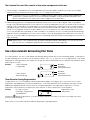
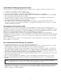
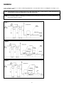
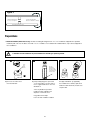
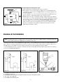
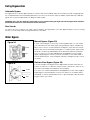
Operating and Service Manual 6200 SXT Chemical Free Iron Filter Made in Canada Introduction Read this Manual First • Read this manual thoroughly to become familiar with the device and its capabilities before installing or operating your Water Filter. Failure to follow instructions in this manual could result in personal injury or property damage. This manual will also help you to get the most out of your filter. • This system and its installation must comply with state and local regulations. Check with your local public works department for plumbing and sanitation codes. In the event the codes conflict with any content in this manual the local codes should be followed. For installations in Massachusetts, Massachusetts Plumbing Code 248 CMR shall be adhered to. Consult your licensed plumber for installation of this system. • This water filter is designed to operate on pressures of 20 psig 125 psig. If the water pressure is higher than the maximum use a pressure reducing valve in the water supply line to the softener. • This unit is capable of operating at temperatures between 40°F and 110°F (4°C - 43°C). Do not use this water filter on hot water supplies. • Do not install this unit where it may be exposed to wet weather, direct sunlight, or temperatures outside of the range specified above. • Do not use water that is microbiologically unsafe without adequate disinfection before or after this system. • This publication is based on information available when approved for printing. Continuing design refinement could cause changes that may not be included in this publication. WaterGroup reserves the right to change the specifications referred to in this literature at any time, without prior notice. Safety Messages Watch for the following safety messages in this manual: NOTE: used to emphasize installation, operation or maintenance information which is important but does not present a hazard. Example: NOTE: Check and comply with you state and local codes. You must follow these guidelines. CAUTION: used when failure to follow directions could result in damage to equipment or property. Example: CAUTION! Disassembly while under pressure can result in flooding. WARNING: used to indicate a hazard which could cause injury or death if ignored. Example: WARNING! ELECTRICAL SHOCK HAZARD! UNPLUG THE UNIT BEFORE REMOVING THE COVER OR ACCESSING ANY INTERNAL CONTROL PARTS NOTE: Do not remove or destroy the serial number. It must be referenced on request for warranty repair or replacement 1 Specification Unit Item # Model # Tank Size 4646 DIF75SXT 8 X 47 Media (CF) Service Flow Rate (gpm) Peak Service Flow Rate (gpm) Backwash Flow Rate (gpm) Shipping Weight (lbs) 5 3.5 110 Chemical Free Iron Filters (IF) 0.75 2 4647 DIF10SXT 9 X 48 1 3 6 4 145 4648 DIF15SXT 10 X 54 1.5 4 10 5 250 4649 DIF20SXT 12 X 52 2 5 15 7 365 4650 DIF15SXT-DH 10 X 54 (DH) 1.5 4 10 5 250 4651 DIF20SXT-DH 12 X 52 (DH) 2 5 15 7 365 Chemical Free Iron Filters Units (IF – M Models) 4652 DIF75MSXT 8 X 47 0.75 2 5 3.5 110 4653 DIF10MSXT 9 X 48 1 3 6 4 145 4654 DIF15MSXT 10 X 54 1.5 4 10 5 250 4655 DIF20MSXT 12 X 52 2 5 15 7 365 4656 DIF15MSXT-DH 10 X 54 (DH) 1.5 4 10 5 250 4657 DIF20MSXT-DH 12 X 52 (DH) 2 5 15 7 365 Working Temperature = 34-110°F (1-43°C) (Do not subject the unit to freezing temperatures) Working Pressure = 20-125 PSIG (137-861 kPa) Voltage = 120V / 60 Hz Pipe Size = 3/4” • At the stated service flow rates, the pressure drop through these devices will not exceed 15 psig. • The manufacturer reserves the right to make product improvements which may deviate from the specifications and descriptions stated herein, without obligation to change previously manufactured products or to note the change. * Do not use water that is microbiologically unsafe without adequate disinfection before or after the system. †U SA customers will need to add “-4” to the item numbers for ordering. Peak flow rates intended for intermittent use only (10 minutes or less) and are for residential applications only. Do not use peak flow rate for commercial applications or for a continuous rate when treated water supplies are geothermal heat pump, swimming pool, etc. For satisfactory operation, the pumping rate of the well system must equal or exceed indicated backwash flow rate. All units come with plastic bypass *Items include brine tank grid Tank jackets are available on 8”, 9” and 10” diameter tanks NC indicates cabinet model, NT indicates twin tank model Water and Time Consumed during regeneration Unit Item # Model # Tank Size Peak Service Service Media Flow Rate Flow Rate (CF) (gpm) (gpm) BackBackwash Shipping Wash Rapid Flow Rate Weight Time Rinse (gpm) (lbs) (Minutes) (Minutes) Total Regeneration Time (Minutes) Water used during Regeneration (gallons) 4646 DIF75SXT 8 X 47 0.75 2 5 3.5 6 4 10 35 35 4647 DIF10SXT 9 X 48 1 3 6 4 6 4 10 40 70 4648 DIF15SXT 10 X 54 1.5 4 10 5 6 4 10 50 80 4649 DIF20SXT 12 X 52 2 5 15 7 6 4 10 70 100 4650 DIF15SXT-DH 10 X 54 (DH) 1.5 4 10 5 6 4 10 50 40 4651 DIF20SXT-DH 12 X 52 (DH) 2 5 15 7 6 4 10 70 50 4652 DIF75MSXT 8 X 47 0.75 2 5 3.5 6 4 10 35 70 4653 DIF10MSXT 9 X 48 1 3 6 4 6 4 10 40 100 4654 DIF15MSXT 10 X 54 1.5 4 10 5 6 4 10 50 35 4655 DIF20MSXT 12 X 52 2 5 15 7 6 4 10 70 40 4656 DIF15MSXT-DH 10 X 54 (DH) 1.5 4 10 5 6 4 10 50 50 4657 DIF20MSXT-DH 12 X 52 (DH) 2 5 15 7 6 4 10 70 70 2 3 The chemical free iron filter consists of two major components which are: 1. A hydrocharger, located between the well head and the pressure tank, adds a small amount of air to the iron-laden water whenever the well pump runs. Refer to Figs. 1, 2 or 3 on Page 8 for its location. NOTE: If your pump system is a constant pressure or variable frequency drive (VFD) the hydrocharger supplied with this filter will not operate properly. The system will require the addition of an air pump and vent tank to introduce the needed air into the water system. Refer to page 8 for more information. 2. A backwashing type filter containing special media that causes the iron in the “hydrocharged” water to precipitate throughout the filter bed (rather than on the surface as in chemical oxidizing filters). This process produces an iron removal capacity of up to 30,000 ppm. The media requires no chemical regenerant for oxygen enrichment. Your filter automatically adjusts the pH to neutral or higher on acid water without an acid neutralizer. The ability to raise pH when it is below neutral (7.0 or less) greatly enhances the filter’s ability to remove iron efficiently. The clean, filtered water then flows into your household water line. Depending on water use and the concentration of iron in your water, periodic backwashing is required to flush the entrapped iron from the system. The filter control can be programmed to backwash once every two, three, four, six or twelve days as required (instructions for calculating backwash frequency and setting the controls are on Pages 20 and 25). NOTE: Replenishment of the media that raises pH will be required periodically, depending on how low the raw water pH is, the amount of manganese (Mn) present in the water and the water usage rate. How a Duro Automatic Backwashing Filter Works In normal operation, the Time of Day display will alternate being viewed with the Day Remaining display. As day passes, the day remaining will count down from a maximum value to zero or (---). Once this occurs, a regeneration cycle will be initiated at the Set Regeneration Time. Water flow through the valve is indicated by the Flow Indicator that will flash in direct relationship to flow rate. Example3 Days Remaining to Regenerate PM Indicator Flow Indicator (Flashing with water flow) 0 Days Treated Water Remaining PM Indicator Flow Indicator (Flashing with water flow) Timer Behavior During Regeneration In regeneration, the control will display a special regeneration display. In this display, the control will show the current regeneration step abbreviation the valve is advancing to or has reached and the time remaining in that step. The step abbreviation displayed will flash until the valve has completed driving into this regeneration step position. Once all regeneration steps have been completed, the valve will return to Service and resume normal operation. Example Less than 6 minutes remaining in Regeneration Step Rapid Rinse 5 Regeneration Step Abbreviation Pushing the during a regeneration cycle will immediately advance the valve to the next cycle step position and resume normal step timing. Please see the control valve manual for different regeneration step abbreviations. 3 Familiarize Yourself with the Unit and Components Control Valve Tank Jacket Tank Media Bed Distributor/Riser 4 5 Installation Instructions Contact your local distributor to use WaterGroup laboratory for complete water analysis free of cost and no obligation to you. All government codes and regulations governing the installation of these devices must be observed. If the ground from the electrical panel or breaker box to the water meter or underground copper pipe is tied to the copper water lines and these lines are cut during installation of the Noryl bypass valve and/or poly pipe, an approved grounding strap must be used between the two lines that have been cut in order to maintain continuity. The length of the grounding strap will depend upon the number of units being installed and/or the amount of copper pipe being replaced with plastic pipe. See Figure 1. In all cases where metal pipe was originally used and is later interrupted by poly pipe or the Noryl bypass valve as in Figure 1 or by physical separation as in Figure 2, an approved ground clamp with no less than #6 copper conductor must be used for continuity, to maintain proper metallic pipe bonding. NOTE: Check your local electrical code for the correct clamp. Before Installation Inspecting and Handling Your Chemical Free Iron Filter Inspect the equipment for any shipping damage. If damaged, notify the transportation company and request a damage inspection. Damage to cartons should also be noted. Handle the filter unit with care. Damage can result if it is dropped or set on sharp, uneven projections on the floor. Do not turn the filter unit upside down. NOTE: If a severe loss in water pressure is observed when the filter unit is initially placed in service, the filter tank may have been laid on its side during transit. If this occurs, backwash the filter to “reclassify” the media. iron (Fe) Iron concentrations as low as 0.3 ppm will cause staining. The iron concentration, together with the flow rate demand and the consumption rate of the water, determines the basic size of the filter system. The higher these factors are, the larger the required system. The filter system is capable of filtering out the three main types of iron found in water supplies: soluble iron (also known as “clear water” or ferrous iron), precipitated iron (also known as “red water” or ferric iron) and bacterial iron (also known as iron bacteria). There is no apparent upper limit of iron concentration for the filter but special care must be taken when selecting a filter model if your water has a combination of high iron, very low pH and/or manganese. Manganese (Mn) The presence of manganese can be bothersome, even for a chemical free iron filter. As little as 0.05 ppm of manganese can produce a brownish or black stain. The ability of the filter to remove manganese depends on its concentration and the pH of the water. Manganese tends to “coat” the filter media, rendering it incapable of increasing the pH and, therefore, ineffective in removing either the iron or the manganese. Manganese, however, will precipitate in the filter bed when the pH is increased. To accomplish this, a special “M” type media that contains additional quantities of the pH raising component (“MpH adder”) can be provided. The use of “M” type media is for applications where the manganese is not more than 1.5 ppm, and the pH is 6.0 or higher. When the pH is below 6.0, consult your dealer. 6 5 pH The pH of water measures its acidity or its alkalinity. Water with a pH of less than 7.0 is acidic, above 7.0 is alkaline, and 7.0 is neutral. The lower the pH value is below 7.0, the greater the acidity and the higher the pH value is above 7.0, the more alkaline. Acidic water (pH less than 7.0) is corrosive to pipes, appliances, etc. A pH of 7.0 or higher facilitates iron removal — which is why the filter is designed to increase the pH when it is less than 7.0. The pH increasing component of the media is “sacrificial”. That is, it slowly dissolves during the process of increasing pH. The rate at which this occurs is proportional to the pH increase and the water consumption rate (i.e. the greater the pH increase and the water consumption, the greater the sacrificial rate). Thus, when the pH is increased to 8.2 or more as is necessary when manganese is present, the sacrificial rate is even greater. Under the most severe conditions, the MpH component of the media may have to be replenished two to four times per year. On the other hand, if the raw water pH is 7.0 or above and no manganese is present, the sacrificial rate is very slight. Tannins (Humic Acid) Tannins (also known as humic acid), which are present in some supplies, are the result of decaying vegetable matter. If the tannin concentration is above approximately 0.5 ppm, it will form a sticky coating on the media, thus rendering it incapable of filtering the iron. A chemical free iron filter is not recommended for this situation. If the tannin concentration is less than 0.5 ppm, a chemical free iron filter may be installed. Hydrogen sulfide (h2s) Hydrogen sulfide (often referred to as “sulfur”), is easily detectable by its objectionable “rotten egg” odor. Sulfur corrodes iron, brass, copper and silver. A chemical free iron filter is not recommended when hydrogen sulfide is the only water problem, although it is capable of removing sulfur in concentrations of up to 2 to 3 ppm. Whenever hydrogen sulfide is present, backwashing must be performed at more frequent intervals and the pumping system MUST include a standard airto-water pressure tank with an air relief valve. Check Your Water Pressure and Pumping Rate Two water system conditions must be checked carefully to avoid unsatisfactory operation or equipment damage: 1. Minimum water pressure required at the filter tank inlet is 20 psi. If pressure is over 50 psi, a pressure reducing valve must be installed in the water supply line ahead of the hydrocharger (Fig. 1, 2 or 3, Page 8). 2. The pumping rate of your well pump must be at least 5 gallons per minute (gpm) for satisfactory operation of the hydrocharger. In addition, the pumping rate must equal the required backwash flow rate of your model (see Specifications on Page 1 for backwash flow rates). To measure the pumping rate of your pump, follow these instructions: a.Make certain no water is being drawn. Open spigot nearest pressure tank. When pump starts, close spigot and measure time (in seconds) to refill pressure tank (when pump shuts off). This figure represents cycle time. b.With the pressure tank full, draw water into a container of known volume and measure the number of gallons drawn until the pump starts again. This is draw-down. Divide this figure by cycle time and multiply the result by 60 to arrive at the pumping rate in gallons per minute (gpm). To aid in your calculation, insert the data in the following formula: DRAWDOWN________÷ CYCLE TIME______________x 60 (gals)(seconds) = PUMPING RATE______________ (gpm) EXAMPLE: DRAWDOWN is 6 gals; CYCLE TIME is 53 secs; then, PUMPING RATE equals: 6 gals ÷ 53 secs x 60 = 6.8 gpm See Specifications on page 2 for minimum flow rates. NOTE: If your pumping rate is inadequate, do not install your filter until the problem is solved. 6 Locate Water Conditioning Equipment Correctly Select the location of your filter tank with care. Various conditions which contribute to proper location are as follows: 1. Locate as close as possible to the water supply source. 2. Locate as close as possible to a floor or laundry tub drain. 3. Locate in correct relationship to other water conditioning equipment (see Fig. 1, 2 or 3, Page 8). 4. Filters and softeners should be located in the supply line before the water heater. Temperatures above 120°F damage filters and softeners and will void the factory warranty. 5. Do not install a filter or softener in a location where freezing temperatures occur. Freezing may cause permanent damage to this type of equipment and will void the factory warranty. 6. Allow sufficient space around the unit for easy servicing. 7. If your water source is a community water supply, a public water supply or you wish to bypass water used for a geothermal heat pump, lawn sprinkling, out-buildings or other high demand applications, refer to Fig. 2 or 3 on Page 8 for additional equipment required. The Importance of Your Pressure Tank The pressure tank found on private well systems becomes an integral part of the filter system by providing necessary mixing and “contact time” to the “hydrocharged” water. While the iron filter will perform better on a standard air-to-water pressure tank, it will perform satisfactorily on a captive air (bladder) pressure tank. The bladder tank requires more careful adjustment of the hydrocharger and careful location of the air relief valve. (see page 17). If cycle time on pumping system is less than 30 seconds and severe operating conditions exist (low pH, high iron, manganese, and small concentrations of sulfur), a standard air-to-water pressure tank with an air-relief valve must be used (if a bladder tank is already in place – do not remove it – install the air-to-water pressure tank between the hydrocharger and the bladder tank). NOTE: If your pressure tank (or any part of your water system) is not functioning properly, corrective action must be taken before installation of your iron filter. Facts to Remember When Planning Your Installation 1. All installation procedures must conform to local and state plumbing codes. 2. All water must pass through the hydrocharger, pressure tank and the filter, or refer to the special instructions for a splitstream installation on Page 18. (System may malfunction if these instructions are ignored.) 3. If lawn sprinkling, a swimming pool, geothermal heating/cooling or water for other devices/activities is to be treated by the filter, a larger model filter must be selected to accommodate the higher flow rate demands of these items. The pumping rate of the well pump must be sufficient to accommodate these items plus the backwash requirement of the filter. Consult your dealer for alternative instructions if the pumping rate is insufficient. 4. Remember that the filter inlet is attached to the pipe that supplies water (i.e., runs to the pump) and the outlet is the line that runs toward the water heater. 5. Before commencing installation, it is advisable to study the existing piping system and determine the size, number and type of fittings required. Typical system schematics shown in these instructions (Fig. 1, 2, or 3, Page 8), will be of assistance. NOTE: If the plumbing system is used as the ground leg of the electric supply, continuity should be maintained by installing ground straps around any nonconductive plastic piping used in installation. 6.When utilizing a constant pressure or VFD pump system you will require the addition of an air pump and vent tank kit #978003 for 115 volt or 978004 for 230 volt systems. A flow switch #79980 will also be required to run the air pump, see Figure 4 on page 9 for installation diagram. 7 8 Installation Proper installation sequence of water conditioning equipment is very important. Refer to the diagrams following for your particular water supply. NOTE: The Braukman air vent is not approved for use in the State of Wisconsin. An approved air to water tank and/or air vent should be used with this application in the State of Wisconsin. NOTE: Before starting installation, read page 18, Plumbing System Clean-Up, for instructions on some procedures that may need to be performed first. Figure 1 Figure 2 Figure 3 8 9 Installation of the Air Pump with Flow Control Switch (Mascontrol) as Power Source 1. U sed when pressure switch and air pump are in alternate locations. Also used on constant pressure or variable speed pump systems. 2. Mascontrol acts as a flow control detecting flow. 3. Connect the air pump to the Mascontrol receptacle. See Mascontrol manual for wiring diagram. 4. A ll government codes and regulations governing the installation of these devices must be observed. Check your local electrical codes or contact a qualified electrician. Figure 4 1. Determine the best location for your water filter, bearing in mind the location of your water supply lines, drain line and 120 volt AC electrical outlet. Subjecting the filter to freezing or temperatures above 43°C (110°F) will void the warranty. 2. Cut main supply line as required to fit hydrocharger in plumbing between well pump and pressure tank (hydrocharger may be installed in a vertical or horizontal position). Allow a minimum of 6 inches straight run of pipe on each side of hydrocharger, excluding fittings. Be certain direction of flow arrow on hydrocharger points toward pressure tank, and pressure control switch is located on pressure tank side of the hydrocharger as in Fig. 1, 2 or 3, (rapid cycling of pump may occur if pressure switch is located on well side. If check valves are used, they should be installed before the hydrocharger – not between the hydrocharger and pressure tank). NOTE: It is advisable to install the hydrocharger with the unions at both ends to facilitate removal and inspection. If heat is applied near hydrocharger, remove rubber check valve to prevent damaging it. On badly scaled, older pumping systems, it may be advantageous to install an optional “Y”-strainer ahead of hydrocharger to prevent plugging hydrocharger nozzle with scale. 9 10 Figure 2 Unfiltered Water Bypass Loop Cut & Capped Ground Strap Required Because of Break in Continuity Filtered Water Line in Home Preparations 1. Media Installation (When Necessary). Models including and higher than 1.5 CF of media are shipped with separate media in pails or boxes. Models lower than 1.5 CF of media come loaded with media and this step can be skipped for new installation. CAUTION! The unit should be de-pressurized before installing or replacing media D a e e Plug the Riser Tube The riser (distributor) remains inside the tank seated in the depression at the bottom C B b a) R emove the valve from the mineral tank. b) Temporarily plug the open end of the riser tube to ensure that no resin or gravel falls down into the distribution. The riser (distributor) remains inside the tank seated in the depression at the bottom. Plug tube with a tape. Remove after media is loaded. 10 11 Fill support bed first. (if supplied) The media will not always spill down inside the tank and may need to be swept inside. Calcium Carbonate & Magnesium Oxide Mixed (Grey / White) Sand Filter Support Bed (when supplied) Fine, Medium and/or Coarse Gravel c. F ill mineral tank one quarter full of water to protect distribution during gravel installation. d. P lace the media into the tank in the order indicated above. Slowly and carefully add the gravel support bed and the softener or filtration media leveling each layer as it is placed into the tank. e. Fill support bed (if supplied) first. During the filling process, ensure the distributor tube stays on the bottom of the tank, reasonably centered. Remove the tape from the distributor once media is loaded. Whenever possible, fill the tank outdoors to avoid problems with dust. If filling indoors, a dust mask should be worn. f The large funnel (sold separately part # 43000) makes filling the tank easier and neater. (Or an empty 1 gallon or 4 liter container with the bottom cut out makes a good funnel.) O-ring f f. Unplug the riser tube, carefully position the valve over it and turn the valve into the threads in the fiberglass tank, tightening securely into tank. Note: Ensure that the internal O-ring in the valve fits securely over the riser tube. Silicone grease (part # 92360) or other food grade lubricant may be applied to the Oring to ease installation of the riser tube. NOTE: Some medias like used in Chemical Free Iron Filter are sacrificial and deplete faster depending on inlet water conditions and usage. The media replenishment is more frequent in high water usage and more acidic water cases. A dome hole models are available and supplied in which the dome hole is available for a quick addition or replenishment of media in the tank 12 11 Dome Hole Cap Dome Hole Cap Removed. CAUTION: make sure the O-Ring is free of defects. Use silicone based lubrication (part # 92360) if neccesary CAUTION! Make sure that the unit is de-pressurized before conducting this task. DO NOT use petroleum based lubricants as they will cause swelling of O-ring seals. The filter is now charged with media. g. It is recommended that the softener or filter tank now be completely filled with water (SLOWLY) to soak the resin or filtration media before startup. This will allow the media to absorb water as well as help displace any trapped air. This will reduce the chance of backwashing resin or filter media out of the tank during the initial backwash on startup. 3.Outside faucets used to water lawns and gardens should not supply softened water. A new water line is often required to be connected to supply hard water to the inlet of the water softener and to the outside faucets. Cut the water line between where it enters the house and before any lines that branch off to feed the hot water heater or other fixtures in the house and as near the desired location of the water softener as possible. Install a tee fitting on the feed end of the cut pipe, and an elbow fitting on the other end. Install piping from the tee to the inlet of the water softener and from the elbow to the outlet of the softener. To sever the water lines which branch off to feed any outside faucets, cut the branch lines approximately two inches from the fitting on the main water line. Install an elbow on the end of the pipe nearest the outside faucet and a cap on the end connected to the existing water line. Install piping from the tee installed on the inlet line to the water softener to the elbow installed on the pipe to the outside faucet. Following this procedure will result in all lines in the house, with the exception of the outside faucets, but including the water heater and therefore the hot water lines, being supplied with soft water. 12 13 Installation Steps: 1 1. C lamp Ring – The clamp ring connects the control valve to the tank and provide an easy way to disconnect tank during control valve servicing. Make sure that the clamp ring screw is tightened. The “Clamp Ring” should secure the valve with the top of the flange facing up. Please note “top” on the clamp ring. Timer Controls Extra Cycle Button Outlet Inlet 2 Drain 1/2” 2. Familiarize yourself with the location of the inlet, outlet and drain on the control valve. Be very careful not to get the controls wet. 13 14 3 UP button DOWN button 3. Familiarize yourself with the buttons on the timer control. 4 Make sure that the flow meter is connected to the outlet of the valve. Flow meter installation is optional. The flow meter is not supplied with the filter. 4. Attach the bypass valve to the control valve (and yoke if plastic bypass is used). Connect the inlet and outlet of the water softener to the plumbing in the house. The control valve must not be submitted to temperatures above 43°C (110°F). When sweat fittings are used, to avoid damaging the control valve, solder the threaded copper adapters to the copper pipe and then, using Teflon tape, screw the assembly into the bypass valve. Yoke Do not use pipe thread compound as it may attack the material in the valve body Bypass . 5 Hose Barb 5. Drain Line Connection: Using teflon tape, screw the 1/2” hose barb into the drain port in the valve. Attach 1/2” drain hose to the hose barb and tighten securely with a hose clamp. Run the drain line to a floor drain or a laundry drain. Complete any necessary plumbing. 5 Connect 1/2” drain hose (not supplied) with a hose clamp here Waste connections or drain outlet shall be designed and constructed to provide for connection to the sanitary waste system through an air-gap of 2 pipe diameters or 1 inch (22 mm) whichever is larger. Never insert drain line directly into a drain, sewer line, or trap. Always allow an air gap between the drain line and the wastewater to prevent the possibility of sewage being back-siphoned into the conditioner. 5 14 15 6 7 outlet intlet 6. Make sure the bypass valve is in the service position. 7. Plug the 24-volt transformer into a 120 VAC 60 Hz outlet. 8 Circuit Board Screen Position Label Brine Cam 8. This valve has two positions: 1) Backwash and 2) Rapid Rinse. When the valve is in the Service position must be pressed and held for 5 seconds before it activates. Press and hold the pic for 5 seconds to advance the valve into the “1” Backwash position. Press once more to advance to the “2” position. The valve position during regeneration and servicing can be checked in the circuit board screen as well the position label on the cam. 15 16 Cycle Step BW RR SV Abbreviation Backwash Rapid Rinse Service Water Conditioner Flow Diagrams Service Position Backwash Position Filtered Water Raw Water Hard Water 10 Filtered Water Raw Water Hard Water Soft Water BW Soft Water To Drain To Drain To Drain to advance the valve to the “1” Backwash po9. Press sition. Slowly turn on the water supply and allow the unit to backwash until the air purges out of the tank and clears the system. 10. Press once more to advance to the “2” Rapid Rinse position and allow water to run to drain for 2 Minutes. Hard Water Soft Waterfor 15 minutes Important: The filter should be backwashed before using this for first time. During initial backwashings, a small amount of fine white media may be observed in the drain water. 11. Press to advance into the service Hard Water the valve back Soft Water position indicated by the in upper left corner of the display. To Drain Rapid Rinse Position Raw Water RR Important Note: Automatic water filters are supplied from the factory in the backwash position, ready for start up. Turn on the water supply to the unit. Open the supply line slowly and allow the air to escape from the filter To Drain before turning the supply water on all the way. Allow the Hard Water Soft Water unit to backwash until all the air and media fines are no longer showing at the drain. This may take up to 15 minutes so you need to unplug the timer until you are ready to continue. 10 Filtered Water To Drain To Drain 12. Set time of the day in the control valve and program the user section of the control. Refer to control valve programming section in this manual. Water Soft Waterdays to NOTE: AfterHard start-up, this filter may take several completely remove the iron. This is normal because of the nature of the media. NOTE: ALL STATE AND LOCAL GOVERNMENT CODES GOVERNING INSTALLATION OF THESE DEVICES MUST BE OBSERVED. 16 17 Set hydrocharger by following these steps: Air Suction Port Figure 6 A. Open nearest faucet until pump starts, then close faucet. B. Place a finger over suction port (Fig. 6) A slight suction should be detected for a minimum of 20 seconds or for approximately one-third of pumping cycle whichever is greater. C.If suction duration is too short, increase by turning water flow adjusting screw (Fig. 6) clockwise. To decrease duration, turn counterclockwise. D. Repeat Steps A through C until proper setting is obtained. When the duration of the suction is too long, cold water may have a “milky” appearance caused by excess air in system. Correct this condition by reducing the duration of suction. This condition is one commonly associated with bladder-type pressure tanks. In extreme cases excess air prevents the system from performing satisfactorily, consequently it is essential to install an air relief valve (such as a Braukman) in the proper location. Screw to adjust flow rate Braukman Air Vent Installation NOTE: The Braukman air vent is not approved for use in the State of Wisconsin. An approved air to water tank and/or air vent should be used with this application in the State of Wisconsin. The Braukman Air Vent must be installed at the highest point of the plumbing, between the pressure tank and filter (see Fig. 7). Please note that the Braukman Air Vent (A) is mounted on a four to six inch pipe extension (B) at the elbow (C) of the highest point. This enables the vent to better collect any excess air created by the hydrocharger. To use the Braukman Air Vent on an air-to-water pressure tank, install it approximately halfway up the side of the tank, as shown in the detailed drawing below. 1 A A B B C Out In open C Braukman Air Vent Out Braukman Air Vent closed In See Figure 8 2 4 5 Pressure Tank (Diaphragm) Figure 7A 3 Pressure Tank (Air to Water) Figure 8 Figure 7B 1. Air Release Cap must be loose or removed to allow air to escape from vent. 2. Vent Bushing 1/2” x 1/8” 3. To opening on side of retention tank (approximately 1/2 way up, from bottom of tank) 4. 3/4” x 3/4” x 1/2” copper tee 5. 3/4” adapter with bushing to tank 17 18 Special Instructions for Split-Stream and Public Water Supply Type Installations: For a split-stream installation, a secondary pressure tank must be installed as in Fig. 2. On a public water supply installation, a pressure tank must be installed as in Fig. 3, Page 8. 1. Install pressure tank (secondary pressure tank in Fig. 2, Page 8) as indicated by appropriate diagram. 2.Install normally-closed solenoid valve after water meter and after a line split for untreated water (if there is one). 3.On both types of installation, install the hydrocharger between pressure tank (secondary pressure tank on split-stream type installations) and normally-closed solenoid valve. 4.Install a pressure switch after the hydrocharger and wire it to the solenoid valve (secondary pressure switch on splitstream). Set high pressure on pressure switch (which controls opening and closing of solenoid valve) to 3 psi lower than low pressure on primary pressure switch. Example: if primary pressure switch is set at 40 to 60 psi, set secondary pressure switch high at 37 to 38 psi. For public water supply installations, contact your local water department or plant operator and ask what the normal low system pressure is. Set high pressure on pressure switch 2 to 3 psi lower than this figure. NOTE: Failure to set the pressure switch as described above will not allow proper closing of the solenoid valve during periods of low system pressure. Plumbing System Clean-Up The following procedures are guidelines only but have proven successful in most instances. Under no circumstances should any procedure outlined below be followed if contrary to the appliance manufacturer’s instructions. Should there by any questions concerning the advisability of performing a procedure, it is strongly recommended the manufacturer’s authorized service outlet be consulted prior to performing the procedure. The plumbing system and water using appliances that have been exposed, even for a short time, to iron-fouled water need to be cleaned of the precipitated iron that has collected in them or iron bleed (staining) will continue to be a problem. Depending on the amount of iron in the water and the length of time the water system has been exposed to iron fouling, select from the following procedures those that apply to the type of system and appliances that need to be cleaned to assure iron-free water at the point of use. Softener It isn’t uncommon that a softener was installed in an effort to remove ferrous (“clear water”) iron from the water supply. Typically, a softener will remove some ferrous iron until the resin bed becomes fouled to the extent that it will lose both hardness removal capacity and the limited capacity for iron removal. This is the condition to expect a softener to be in when planning a system clean-up. Prior to closing main supply valve or turning power off to a private well system and preparatory to installing the filter system, do the following: 1.Disconnect brine draw line from the brine cabinet and place the loose end into a five gallon plastic pail filled with a solution of warm water and 4 oz. of resin mineral cleaner. 2.Manually advance control timer to brine draw position (refer to instructions provided with your softener). Allow all the warm mineral cleaner solution to be drawn into mineral bed. Then immediately: 3.Close main water supply valve or turn power off to pump and proceed with filter installation. During time required to install filter system, iron-fouled softener resin will be chemically cleaned. 4.After filter installation is completed and final adjustments are made with the water turned on and brine draw tube reconnected, manually reposition timer on softener to backwash position. Allow timer to perform an automatic regeneration cycle. During backwash of softener, all iron cleaned from the resin will be washed down the drain. It is advisable, after chemically cleaning softener, to regenerate system twice to fully restore capacity lost due to iron fouling. 18 19 System Check List More than 90% of problems affecting the efficiency of a chemical iron free filter system can be identified in 9 minutes or less by following this diagnostic schedule. Start with Step 1, then follow each step in sequence to ensure proper diagnostic procedures. 1. Check for Proper Installation a. Is the hydrocharger installed between well pump and pressure tank with arrow pointing toward pressure tank? b.Is there a minimum of 6 inches on the hydrocharger inlet and 6 inches on the outlet of the straight pipe, free of pipe fittings? c. d.Is the pipe from the pressure tank to the filter unit attached to the inlet port of the control valve? Is the pipe from the filter unit to the water heater attached to the outlet port of the control valve? e.Is the drain line of adequate diameter? Drain line must be sized to prevent back pressure from reducing backwash frow rate below minimum for the model installed. Typical examples of minimum drain line diameters are: Is the check valve (if used) correctly located between the pump and the hydrocharger? i) 1/2” ID when drain is up to 15 ft from unit and backwash discharge point is lower than the control valve ii)5/8” ID when drain is up to 15 ft from unit and backwash water discharge point is slightly higher than the control valve iii)3/4” ID when drain is 25 ft away and/or drain is installed overhead f. Has the drain line been “kinked”? A kinked drain line must be replaced. g.Is the drain line installed in a way that it will freeze in cold weather? h.If the system incorporates a standard air-to-water pressure tank, does it have the required deep well air volume control (air release valve) and is it functioning? (Proper installation of this type of pressure tank should have inlet from pump higher than outlet to service.) 2. Check pH, Iron and Manganese Content of Treated Water Is the treated water pH reading less than 6.7 (8.2 when manganese is present)? If yes, replenish the media with MpH adder and check the bed for “channelling”. 3. Check Pumping Rate Do not refer to a pumping rate curve for this data. Follow the instructions found on Page 7. Is the measured pumping rate less than the backwash rate of the filter? If yes, increase the pumping rate by first reducing the system operating pressure. If the pumping rate is still too low, replace the pump. 4. Check Hydrocharger for Proper Air Draw Does air suction continue for 1/3 of the time the pump runs (do not confuse with 1/3 of the pressure range)? Turn the water flow adjusting screw clockwise to increase the draw time and counter-clockwise to decrease the draw time. 5. Manually Stage Filter Control to Backwash Cycle Does a “rush” of air precede the backwash water out of the drain line? (If no, proceed to Step 6). If yes, the system is “air-logged”. Disconnect power from the pump and allow the system pressure to drop to zero through the filter drain line. Restore power and rebuild system pressure. Continue backwashing unit until the pump has completed two or three pressure cycles. Stage control valve to the service position and check the hydrocharger draw time. Adjust draw for 1/3 of pump cycle time. 6. Determine Other Uses of Water in Addition to Normal Domestic Purposes (e.g. geothermal heating or cooling, swimming pool fill, lawn irrigation, farm animal watering, etc.) Have any high demand water uses been added subsequent to the installation of the filter system or overlooked when originally sizing the system? (If a high demand situation exists, resize the system using continuous service flow rate data.) 19 20 Programming Instructions Set Time of Day Press and hold or buttons until display reads TD. Adjust the displayed time with or buttons. Press to resume normal operation. Queuing a Regeneration 1. P ress the button. The service icon will flash to indicate that a regeneration is queued. 2. T o cancel a queued regeneration, press the button. Regenerating Immediately Press and hold the button for five seconds. User Programming Mode Options Description OFF Abbreviation Parameter DO Day Override The timer’s day override setting This is an option only. Please do not adjust before consulting an authorized dealer. RT Regeneration Time The time of day that the system will regenerate (meter delayed, timeclock, and day-of-week systems) CD Current Day The current day of week User Programming Mode Steps Note: Use and parameters. Down button to adjust values for In the second level mode, the control valve has been programmed as per the following main parameters related to regeneration. For more information on master programming manual, read control valve manual part # 54802. 1. P ress the and buttons for five seconds while in service, and the time of day is NOT set to 12:01 PM. OFF The valve has been pre-programmed with factory settings as shown in the following chart: 2. U se this display to adjust the Day Override. Adjust this to “12” parameter for softeners. OFF Regeneration Cycle Step Programming 3. P ress the button. Use this display to adjust the Regeneration Time. 4. P ress the button. Use this display to set the Current Day of the Week. This option setting is identified by “CD” in the upper left hand corner of the screen. This option is only available after the Day of the Week control is set to ‘ON’ in the Master Programming. Refer to the valve manual for details. 5. Press the button to end User Programming Mode. 20 21 1. Backwash 6 minutes 2. Rapid Rinse 4 minutes Diagnostic Programming Mode Diagnostic Programming Mode Options Abbreviation Parameter Description FR Flow Rate Displays the current outlet flow rate PF Peak Flow Rate Displays the highest flow rate measured since the last regeneration HR Hours in Service Displays the total hours that the unit has been in service VU Volume Used Displays the total volume of water treated by the unit RC Reserve Capacity Displays the system’s reserve capacity calculated from the system capacity, feed water hardness, and safety factor SV Software Version Displays the software version installed on the controller NOTES: Some items may not be shown depending on timer configuration. The timer will exit Diagnostic Mode after 60 seconds if no buttons are pressed. Press the Extra Cycle button to exit Diagnostic Mode at any time. Diagnostic Programming Mode Steps 1. Press the service. and 5. Press . Use this display to view the Volume Used since the last regeneration cycle. This option setting is identified by “VU” in the upper left hand corner of the screen. buttons for five seconds while in 2. Use this display to view the current Flow Rate. This option setting is identified by “FR” in the upper left hand corner of the screen. 6. Press . Use this display to view the Reserve Capacity. This option setting is identified by “RC” in the upper left hand corner of the screen. 3. Press . Use this display to view the Peak Flow Rate since the last regeneration cycle. This option setting is identified by “PF” in the upper left hand corner of the screen. 7. Press . Use this display to view the Software Version. This option setting is identified by “SV” in the upper left hand corner of the screen. 4. Press . Use this display to view the Hours in Service since the last regeneration cycle. This option setting is identified by “HR” in the upper left hand corner of the screen. 8. Press 21 22 to end Diagnostic Programming Mode. Controller Behavior Control Operation During Programming The control will only enter the Program Mode with the valve in Service. While in the Program Mode, the control will continue to operate normally, monitoring days and keeping all displays up to date. Control programming is stored in memory permanently, eliminating the need for battery back-up power. Time Clock Delayed Control A Time Clock Delayed Control regenerates the system on a timed interval. The control will initiate a regeneration cycle at the programmed regeneration time when the number of days since the last regeneration equals the regeneration day override value. Day of the Week Control This control regenerates the system on a weekly schedule. The schedule is defined in Master Programming by setting each day to either “off” or “on.” The control will initiates a regeneration cycle on days that have been set to “on” at the specified regeneration time. Control Operation During a Power Failure The SXT includes integral power backup. In the event of power failure, the control shifts into a power-saving mode. The control stops monitoring water usage, and the display and motor shut down, but it continues to keep track of the time and day for a minimum of 48 hours. The system configuration settings are stored in a non-volatile memory and are stored indefinitely with or without line power. The Time of Day flashes when there has been a power failure. Press any button to stop the Time of Day from flashing. If power fails while the unit is in regeneration, the control will save the current valve position before it shuts down. When power is restored, the control will resume the regeneration cycle from the point where power failed. Note that if power fails during a regeneration cycle, the valve will remain in it’s current position until power is restored. The valve system should include all required safety components to prevent overflows resulting from a power failure during regeneration. The control will not start a new regeneration cycle without line power. If the valve misses a scheduled regeneration due to a power failure, it will queue a regeneration. Once power is restored, the control will initiate a regeneration cycle the next time that the Time of Day equals the programmed regeneration time. Typically, this means that the valve will regenerate one day after it was originally scheduled. If the treated water output is important and power interruptions are expected, the system should be setup with a sufficient reserve capacity to compensate for regeneration delays. 7 22 During Regeneration Automatic Bypass The regeneration cycle lasts approximately 15 minutes, after which treated water service will be restored. During regeneration, untreated water is automatically bypassed for use in the household. Hot water should be used as little as possible during this time to prevent hard water from filling the water heater. IMPORTANT: This is why the automatic regeneration is set for sometime during the night and manual regenerations should be performed when little or no water will be used in the household. New Sounds You may notice new sounds as your water softener operates. The regeneration cycle lasts approximately 2-1/2 hours. During this time, you may hear water running intermittently to the drain. Water Bypass Manual Bypass (Figure 5A) Figure 5A Outlet Inlet In case of an emergency such as an overflowing brine tank, you can isolate your water filter from the water supply using the bypass valve located at the back of the control. In normal operation the bypass is open with the ON/OFF knobs in line with the INLET and OUTLET pipes. To isolate the filter, simply rotate the knobs clockwise (as indicated by the word BYPASS and arrow) until they lock. You can use your water related fixtures and appliances as the water supply is bypassing the softener. However, the water you use will be hard. To resume treated service, open the bypass valve by rotating the knobs counterclockwise. Stainless Steel Bypass (Figure 5B) Figure 5B In normal operation the bypass lever is aligned with the inlet/outlet with the pointer on SERVICE. To isolate the softener or filter, rotate lever counter clockwise until it stops and pointer indicates unit is in bypass. Outlet Inlet You can use your water related fixtures and appliances as the water supply is bypassing the softener and filter. However, the water you use will be hard or untreated. To resume treated water service, open the bypass valve by reversing the rotation of the lever. 23 Operating Conditions Water Heater If the water heater has been exposed to both iron and hardness for a long period of time, replacement of the heater tank maybe the only practical solution to prevent continued staining originating from this source. After completing the installation of the chemical free iron filter system, clean the water heater by following these instructions: 1. Shut off energy supply to water heater and close heater inlet water valve. 2. D rain hot water tank completely. Open inlet water valve allowing heater tank to be refilled with iron-free water. Continue flushing until water runs clear to drain. 3. If, after approximately 30 minutes flushing, water does NOT clear, terminate flushing operation. Refill hot water heater with water and pour approximately 1/2 gallon of household bleach into top of heater tank. Allow bleach solution to stand in tank for 20 to 30 minutes. Flush tank again until water is clear at drain. Turn energy supply on. NOTE: If water does not clear in approximately 10 minutes, water heater should probably be replaced. Dishwasher Consult owners’ handbook and follow manufacturer’s instructions. Toilet Flush Tanks Prior to commencing installation of the filter system, pour 4 to 6 ounces of resin mineral cleaner Pro-Rust Out or inhibited muriatic acid into flush tanks and bowls and let stand. When installation is completed, flush toilets several times with iron-free water. If iron deposits or stains remain, repeat procedure until clear. Maintenance Instructions Your chem free iron filter requires some minor maintenance to ensure optimum performance and years of trouble-free clean water. The following steps should be performed once or twice a year (more often under harsh conditions): 1. V erify the pumping rate of the system - do not refer to a pumping curve for this data. Follow the instructions found on page 7. If the measured pumping rate is less than the backwash rate of the filter, see page 39, Trouble Shooting. 2. H ave your water tested - for pH, iron and manganese on both the treated and raw water to ensure your water conditions haven’t changed. 3. Inspect the hydrocharger and the piping between the iron filter and the pressure tank to ensure they are not plugged with raw iron. If the line becomes plugged, the flow of water to the home will be reduced. This will result in a reduction of water available for backwashing the unit which will inhibit operation of the system. 4. A ir-to-water pressure tank - periodically drain and flush your tank to prevent a build-up of precipitated iron from forming in the bottom of the tank. 5. B ladder tank - periodically check that the bladder air pressure remains at 2 psi lower than the cut-in pressure of your pump. 6. C heck the hydrocharger - to ensure it is drawing air properly and for the correct amount of time (1/3 of the pump cycle time or 20 seconds, whichever is greater). 7. F or applications with low pH, manganese or hydrogen sulfide, consult your local dealer for specific instructions to maintain the efficiency and operation of your filter. 8. Periodic cleaning of the air vent assembly with mild acid or vinegar will ensure that it continues to vent excess air properly. 9. The filter tank can be cleaned with a mild soap solution. 10. Never subject the unit to freezing. 24 25 Maintenance Instructions (continued) Care of Your Filter To retain the attractive appearance of your new water filter, clean occasionally with a mild soap solution. Do not use abrasive cleaners, ammonia or solvents. Never subject your softener to freezing or to temperatures above 43°C (110°F). Servicing Components. • T he seals and spacer cartridge should be inspected/cleaned or replaced every year depending on the inlet water quality and water usage. • The media should be replenished or replaced depending of inlet water quality and water consumption. Check with your water treatment expert on the media bed change frequency. Below are some guidelines Please refer to the servicing section of this manual for step by step procedure. Not following the above will void all warranty on the control valve. Maintenance of your new water filter requires very little time or effort but it is essential. Regular maintenance will ensure many years of efficient and trouble free operation. Replacing Media Bed The media bed in a neutralizing filter is slowly dissolved and has to be replaced. The frequency of replacement varies, depending on water quality - consult your dealer to determine the expected life of your media bed. Backwashing Instructions To Calculate Backwash Frequency - Normal Applications Backwash frequency for households with average water use can be determined using the following guide. The guide cannot be used if the filtered water supplies a swimming pool, geothermal pump, outside spigots or other high water demand devices or activities. If your application includes any of the foregoing refer to the paragraph on “Special Applications” below. People in Family 1 2 3 4 5 6 Iron Content (ppm) 2 4 6 8 101214161820 1111111111 1111122222 1112223333 1122233444 1122334466 1223346666 1.Locate the box intersected by the number of people in your family and the parts per million (ppm) of iron in your water (if your ppm is between two numbers on the guide, use the higher number). 2. The number in the box represents how many times your filter has to backwash in a twelve day schedule. Example: You have four in the family and 8 ppm of iron. Refer to the guide and locate the box intersected by four in the family and 8 ppm of iron. The figure supplied is 2. This means your filter control should be programmed to backwash twice in twelve days — that is every sixth day. If the figure had been 3 it would mean 3 backwashes in twelve days or every fourth day. To Calculate Backwash Frequency - Special Applications To ensure adequate reserve capacity and prevent loss of water pressure between backwashes the figure of 15,000 (not the full 30,000 ppm capacity) is used to calculate backwash frequency. Determine your backwash frequency as follows: 10 25 1. Estimate daily iron removal requirements using the following calculation: No. of people in family x 75 gallons of water per person + No. of gallons of water for special use = No. of gallons of water required per day x Iron concentration (ppm) = Daily iron removal requirements (ppm) 2. Establish backwash frequency using daily iron removal requirements to complete the following calculation: 15,000 iron removal capacity (ppm) ÷ Daily iron removal requirements (ppm) = No. of backwashes required in 12 day schedule Example: You have four in the family, 8 ppm of iron and a swimming pool requiring 46 gallons of water per day. 4 x 75 300 + 46 346 x 8 2,768 People in the family Gallons of water per person Gallons of water for family Gallons of water for the pool Gallons of water required per day Iron concentration Daily iron removal requirements (ppm) 15,000 ÷ 2,768 5.4 Iron removal capacity (ppm) Daily iron removal requirements (ppm) Backwash frequency (days) The calculation indicates the need to backwash every 5.4 days. The control can only be programmed to backwash at intervals of two, three, four, six and twelve days. The control would be programmed to the closest more frequent setting i.e. every four days. Servicing 6200 Valve Before Servicing 1. Turn off water supply to conditioner : a. If the conditioner installation has a 3 valve bypass system first open the valve in the bypass line, then close the valves at the conditioner inlet & outlet. b. If the conditioner has an integral bypass valve, put it in the bypass position. c. If there is only a shut-off valve near the conditioner inlet, close it. 2. R elieve water pressure in the conditioner by stepping the control into the backwash position momentarily. Return the control to the In Service position. 3. Unplug Electrical Cord from outlet. 4. D isconnect drain line connection. WARNING! E LECTRICAL SHOCK HAZARD! UNPLUG THE UNIT BEFORE REMOVING THE COVER OR ACCESSING ANY INTERNAL CONTROL PARTS. CAUTION! D isassembly while under pressure can result in flooding. Always follow these steps prior to servicing the valve. 26 27 6200 Service Kits – Piston and Cartridge Assembly O-Ring 97 O-Ring 98 Blank 7 6 5 1 2 3 4 REVISIONS ECN ZONE REV. DATE DESCRIPTION APP'D 100 D Blank 101 C Dwg # Part # Part Description 7 61799-01 Cartridge Assembly with Piston 76 11335 Screw, 4-40X3/16 97 16394 O-Ring, 029 98 13287 O-Ring, 123 99 61799 Seal and Spacer Cartridge 100 42920 Piston 101 19984 Piston Rod 76 B LAST SAVED IN SMARTEAM: LEVEL I LEVEL II DO NOT SCALE DRAWING. DIMS. ARE IN INCHES [mm] INTERPRET DIMS AND TOLERANCES PER ASME Y14.5M -1994 UNLESS OTHERWISE SPECIFIED: CORNER FILLETS R.005-.020 [.127-.508] TOLERANCES: ANGLES : 1 1 PLACE .X: .015 [0.38] 2 PLACE .XX: .01 [0.3] 3 PLACE .XXX: .005 [0.13] 7 6 5 4 3 O-Ring 97 DATE AND TIME CRITICALITY SYMBOLS PER QPSP-001.2 THIS DOCUMENT IS SOLELY THE PROPERTY OF PENTAIR WATER TREATMENT. REPRODUCTION, USE DISCLOSURE, OR TRANSMISSION OF THIS DOCUMENT OR DETAILS CONTAINED HEREIN, IN PART OR IN WHOLE, IS PROHIBITED WITHOUT THE WRITTEN CONSENT OF PENTAIR WATER TREATMENT ENGINEERING. THIS DOCUMENT AND ANY COPIES SHALL BE RETURNED TO PENTAIR WATER TREATMENT UPON WRITTEN REQUEST. LEVEL III A THE COMPONENT, PART, OR ASSEMBLY DESCRIBED IN THIS DOCUMENT MUST COMPLY WITH THE EU (EUROPEAN UNION) DIRECTIVE: RoHS DIRECTIVE 2002/95/EC, THIS DRAWING MUST BE COMPARED TO THE ERP SYSTEM TO ENSURE CORRECT REVISION LEVEL PRIOR TO USE. THIRD ANGLE PROJECTION APPROVALS DRAWN CHECKED APPROVED 2 DATE Pentair Residential Filtration TITLE SIZE SCALE D 1:1 DWG NO. REV _ SOLIDWORKS FORMAT SHEET 4 OF 4 1 O-Ring 97 7 99 6200 Service Kits – Drain Line Flow Control Kits Dwg # 19 61 61 62 63 88 12086 Washer, Flow, 1.50 GPM 12087 Washer, Flow, 2.0 GPM 12088 Washer, Flow, 2.4 GPM 12089 Washer, Flow, 3.0 GPM 12090 Washer, Flow, 3.5 GPM 12091 Washer, Flow, 4.0 GPM 12092 Washer, Flow, 5.0 GPM 11183 O-Ring, 017 63 11385-01 89 19 27 Part Description Washer, Flow, 1.2 GPM 62 88 89 Part # 12085 13308 12388 Adapter, Fitting, DLFC Hose Barb, Straight, DLFC,1/2" Hose Barb, 90 Deg, DLFC,1/2" 60705-XX DLFC Assembly, XX GPM For < 7 GPM 60706-XX DLFC Assembly, XX GPM For > 7 GPM 18312 Retainer, Drain 6200 Service Kits – Flow Meter (Optional) 84 24 22 Dwg # Part # Part Description 84 19791-01 22 19569 Clip, Flow Meter Cable, Meter 24 13314 Screw, Slot Hex, 8-18 X0.6 23 19797 Meter, Assy,3 /4" Dual Port 105 13305 O-Ring, -119 21 14613 Flow Straightener 94 60626 Meter Only, Electronic Turbine 21 23 94 105 6200 Service Kits – Circuit Board Dwg # 37 Part # Part Description 82 19474-01 Harness, Power, SXT 84 19791-01 Cable Meter 36 42766-02 Circuit Board, SXT 37 17020 Screw 36 84 82 28 6200 Service Kits – Other Parts Dwg # Part # Part Description 37 17020 Screw, Stl Hex, 6-20 X 3/8 51 040050 Screw, Hex Washer 34 42919 Cam, Brine 43107 Label, Cam Position, Softener 85 43121 Label, Cam Position, Filter 24 13314 Screw, Slot, Hex, 8-18 X 0.60 87 18280 Collector, Top, 1" 48 19619 Bracket, Idler 47 43298 Gear Idler 42 10218 Switch, Micro 51 37 34 42 85 47 24 87 48 35 49 40 54 Dwg # 40 41 31 43 55 37 32 29 Part # Part Description 43052-01 Cover, Black 43052-02 Cover, Cream 54 10231 Screw, Slot Hex, 1/4-20 X 1/2 49 19597 Motor, 24V, 50/60 Hz 43053-01 Backplate, Black 35 43053-02 Backplate, Cream 41 19581 Bracket, Drive 43 10302 Insulator, Limit Switch 32 019688 Link, Piston Rod 31 019493 Shaft, Drive 55 13363 Washer 37 17020 Screw, Hex, 6-20 X 3/8 6200 Service Kits – Other Parts Continued Dwg # Part # Part Description 28 19998 Shaft, Drive 27 40057 Screw, Hex Washer Head 26 40254 Clamp, Ring 92 60503 Clamp Ring Assembly 26 27 28 92 Bypass Valve Assembly & Yokes (Plastic) Item No. Quantity Part No. 1 2 13305 Description O-ring, -119 2 2 13255 Clip, Mounting 3 2 13314 Screw, Hex Washer Head, 8-18 x 5/8 4A 1 18706 Yoke, Plastic, 1” NPT 18706-02 Yoke, Plastic, 3/4” NPT 4B 1 13708 13708NP 13398 13398NP 40636 Yoke, Brass, 3/4” NPT Yoke, 3/4” NPT Nickel Plated Yoke, Brass, 1” NPT Yoke, 1” NPT Nickel Plated Yoke, 1 1/4” NPT 40636-49 Yoke, 1 1/4” Sweat 30 Timer Replacement Meter Cable Screw Self tapping screw Screw Brine Valve Brine Cam 1.Disconnect the meter cable from the meter. (If flow meter is attached) 2.Open the front cover of the control valve, unscrew the brine cam and push the brine valve in order to remove the cam. Bracket 3.Remove the two screws from the grey brine valve bracket and remove it from the valve back plate. Timer Assembly Screw Piston screw 4.Remove the piston screw from the piston rod. Screw 5.Remove the three screws from the front bracket. The entire timer assembly will disconnect from the valve body. 6.Replace the timer with a new one. Attach the three screws to the front bracket and piston screw to the piston rod. Reinstall the brine valve bracket. Reinstall brine cam. Close the front cover of the control valve. 7. Reconnect meter cable. (If flow meter is attached) 32 31 Piston Cartridge Assembly Replacement 7 8 6 5 3 4 All 5 O-rings need to be inspected for damages and lubricated 1 2 REVISIONS ECN ZONE D REV. DATE DESCRIPTION APP'D D C C B B DATE AND TIME LAST SAVED IN SMARTEAM: A CRITICALITY SYMBOLS PER QPSP-001.2 LEVEL I LEVEL II THIS DOCUMENT IS SOLELY THE PROPERTY OF PENTAIR WATER TREATMENT. REPRODUCTION, USE DISCLOSURE, OR TRANSMISSION OF THIS DOCUMENT OR DETAILS CONTAINED HEREIN, IN PART OR IN WHOLE, IS PROHIBITED WITHOUT THE WRITTEN CONSENT OF PENTAIR WATER TREATMENT ENGINEERING. THIS DOCUMENT AND ANY COPIES SHALL BE RETURNED TO PENTAIR WATER TREATMENT UPON WRITTEN REQUEST. DO NOT SCALE DRAWING. DIMS. ARE IN INCHES [mm] INTERPRET DIMS AND TOLERANCES PER ASME Y14.5M -1994 UNLESS OTHERWISE SPECIFIED: CORNER FILLETS R.005-.020 [.127-.508] TOLERANCES: ANGLES : 1 1 PLACE .X: .015 [0.38] 2 PLACE .XX: .01 [0.3] 3 PLACE .XXX: .005 [0.13] BR42889 8 7 6 5 4 3 LEVEL III A THE COMPONENT, PART, OR ASSEMBLY DESCRIBED IN THIS DOCUMENT MUST COMPLY WITH THE EU (EUROPEAN UNION) DIRECTIVE: RoHS DIRECTIVE 2002/95/EC, THIS DRAWING MUST BE COMPARED TO THE ERP SYSTEM TO ENSURE CORRECT REVISION LEVEL PRIOR TO USE. THIRD ANGLE PROJECTION APPROVALS DRAWN CHECKED APPROVED DATE Pentair Residential Filtration TITLE SIZE SCALE D 1:1 DWG NO. REV _ SOLIDWORKS FORMAT 2 SHEET 4 OF 4 1 This O-ring goes to the bottom of the cartridge Cartridge Assembly 1.Follow steps 1 to 5 of timer replacement. 2.Use a flat head screw drive on the notch of the valve body as shown to loosen the piston cartridge, pull the cartridge out of the body using pliers. 3.Inspect the inside of the valve to make sure that there is no foreign matter that would interfere with the valve operation. 4.Put food grade silicone grease on the o-rings of the new piston cartridge assembly and install it inside the valve body. 5.Reinstall the timer assembly, brine valve bracket and meter cable. Meter Replacement and Service Meter Cable Outlet Port Lubricate O-rings Meter Assembly Clip Flow Meter should be attached to the outlet side of the valve Screw 4.Apply silicone lubricant to four new o-rings and assemble to four ports on new meter module. 5.Assemble meter to control valve. Note, meter portion of module must be assembled at valve outlet. 6.Push resin tank back to the plumbing connections and engage meter ports with bypass valve or yoke. 7.Attach two clips and screws at bypass valve or yoke. Be sure clip legs are firmly engaged with lugs. Flow Straightainer Inside the Outlet Port 1.Disconnect the meter cable from the meter. 2.Remove two screws and clips at bypass valve or yoke. Pull resin tank away from plumbing connections. 3.Pull meter module out from control valve. 33 32 Servicing and Replacing Drain Line Flow Control (DLFC) 1. Disconnect the drain line retainer clip. 2.Remove the DLFC assembly and pull the flow washer out of the DLFC housing with the help of plier. 3.Remove the flow washer from the housing and clean it with water to remove any debris. Replace it with a new washer if necessary. 4. Re-install the DLFC housing and retainer. DLFC Retainer Flow Washer Housing Flow Washer Hose Barb 34 33 Circuit Board Replacement Screws Meter Cable Power Harness 1.Detach the circuit board from valve front cover by removing two screws. 2.Disconnect the meter cable and power head harness from the circuit board. 3.Replace and connect the new circuit board on the front cover. After Servicing 1. Reconnect drain line. 2. Return bypass or inlet valve to normal in service position. Water Pressure will automatically build in the softener. NOTE: Be sure to shut off any bypass line. 3. Check for leaks at all sealed areas. Check Drain seal with the control in the backwash position. 4. Plug electrical cord into outlet. 5. Set Time of Day and cycle the control valve manually to assure proper function. Make sure control valve is returned to the In Service position. 6. Start regeneration cycle manually if water is hard. 35 34 6200 SXT Valve Dimensional Drawings All dimensions are in Inches (mm). 36 35 Parts Breakdown 2 3 5 4 1 Part Number Model Distributor (1) Valve (2) Tank (3) Media Bed (4) Tank Jacket (5) Tee 4646 DIF75SXT 19478 6200227 18474 95431 100502 0500356 4647 DIF10SXT 19478 6200228 194804 95550 100505 0500356 4648 DIF15SXT 19477 6200229 110544 95551 100508 0500356 4649 DIF20SXT 19477 6200230 112524 95427 0500356 4650 DIF15SXT-DH 19477 6200229 81150 95551 0500356 4451 DIF20SXT-DH 19477 6200230 81152 95427 4652 DIF75MSXT 19478 6200227 18474 95432 100502 0500356 4653 DIF10MSXT 19478 6200228 194804 95553 100505 0500356 4654 DIF15MSXT 19477 6200229 110544 95554 100508 0500356 4655 DIF20MSXT 19477 6200230 112524 95428 0500356 4656 DIF15MSXT-DH 19477 6200229 81150 95554 0500356 4657 DIF20MSXT-DH 19477 6200230 81152 95428 0500356 Common Components 60049 Bypass 0550119 - Bushing 50701 - Air Vent 33350 - Hydrocharger Assembly 36 0500356 Parts Dimensions E A C B D Dimesions (inches) DIF75SXT DIF75MSXT DIF10SXT DIF10MSXT DIF15SXT DIF15MSXT DIF20SXT DIF20MSXT DIF15SXT-DH DIF15MSXT-DH DIF20SXT-DH DIF20MSXT-DH A 8 10 12 14 9 19 B 54 54 59 57 55 61 C 19 19 19 19 19 19 D 49 49 54 52 50 56 E 2 2 2 2 2 2 8 37 Trouble Shooting Guide Error Codes Note: Error codes appear on the In Service display Error Code Probable Cause Recover and Resetting [Err 0] Drive motor is stalled Unplug the unit from the power source [Err 1] Drive motor is running continuously When power is restored to the unit, the Err _ display code clears. If the condition causing the error has not been resolved the Err _ code reappears in the four digit display. Do not attempt to troubleshoot this problem any further. [Err 2] There have been more than 99 days since the last Regeneration. If the Day of the Week mode of regeneration is selected and days since last regeneration exceeds 7 days. Regeneration must occur for the unit to recover, the display to clear and the valve to function normally. [ 7 - - 5 ]: There have been more than 7 days since the last regeneration. All individual settings (d1, d2, d3, d4, d5, d6, d7) are set to 0. [Err 3] Control board memory failure. [ 7 - - 5 ]: To recover from [Err2], the user must initiate a regeneration or set at least one individual day to 1. Perform a Master Reset. If the error returns, do not attempt to troubleshoot this problem any further. Error Display Example NOTE: Unit will flash when an error exists. 38 39 Trouble Shooting Guide 1. Water is clear when drawn, turns red upon standing (stain producing) Insufficient air drawn by hydrocharger - Check hydrocharger adjustment. If unable to adjust for long enough draw, check pumping rate. Bypass open or leaking - Close bypass valve and/or repair as necessary. Filter bed backwashed at improper intervals - Refer to backwash frequency chart in operation manual to ensure unit is set correctly. Do not increase the backwash frequency unless required to based on the chart, since the media needs to be some what iron-fouled for best performance (in more severe iron-fouling cases, filter bed may need chemical cleaning — contact dealer). Presence of manganese or tannins - Recheck water analysis. Flow rate excessive for model - Reread Sec. 2: Facts To Remember When Planning Your Installation, Page 3. Check-valve located between hydro-charger and pressure tank, disrupting water flow - Relocate check-valve. Pumping cycle too short. pH of treated water too low (should be 7.0 or higher; with manganese, pH must be 8.2) - Lengthen pump cycle time. Replenish MpH component in media (contact dealer). 2. Water is red when drawn from tap Filter bed overloaded with precipitated iron due to insufficient backwash flow rate - a) Recheck well pumping rate and repair or replace as required. (b) Check for obstructions or kink in drain line, or (c) for improper drain line flow controller (see specs). Upon correction of this problem, if manually backwashing does not clear bed of iron, filter bed may need chemical cleaning Filter bed backwashed at improper intervals - Refer to backwash frequency chart in operation manual to ensure unit is set correctly. Do not increase the backwash frequency unless required to based on the chart, since the media needs to be some what iron-fouled for best performance (in more severe iron-fouling cases, filter bed may need chemical cleaning — contact dealer) Solenoid valve malfunction or inadequate supply system pressure/flow rate - Solenoid valve malfunction or inadequate supply system pressure/flow rate 3. Excessive pressure loss through filter Filter bed overloaded with precipitated iron - Refer to Section 2 above. Control inlet/outlet valve(s) not fully open - open valves Sand, silt or mud collecting in filter media - check well for these conditions Filter bed not properly “classified” - Manually backwash to reclassify. “Cementing” or “channelling” of filter media - Prod (stir) filter bed to break up hardened layer, backwash frequency to prevent recurrence.increase 4.“MILKY” OR “BUBBLY” WATER (APPEARS TO CONTAIN SMALL BUBBLES) Excess hydrocharger air-draw - Check adjustment for duration of draw in excess of one-third pumping cycle (see Step 9, Page 6). Excess gases in water (carbon dioxide, hydrogen sulfide, methane) - May require cleaning or installation or air-relief control (contact dealer). 13 39 Duro Guarantee WaterGroup Inc. guarantees that your new water conditioner is built of quality material and workmanship. When properly installed and maintained, it will give years of trouble free service. Seven Year Complete Parts Guarantee: WaterGroup Inc. will replace any part which fails within 60 months from date of manufacture, as indicated by the serial number provided the failure is due to a defect in material or workmanship. The only exception shall be when proof of purchase or installation is provided and then the warranty period shall be from the date thereof. Ten Year Guarantee on Mineral Tanks and Brine Tanks: WaterGroup Inc. will provide a replacement mineral tank or brine tank to any original equipment purchaser in possession of a tank that fails within 120 months, provided that the water conditioner is at all times operated in accordance with specifications and not subject to freezing. General Provisions: WaterGroup Inc. assumes no responsibility for consequential damage, labor or expense incurred as a result of a defect or for failure to meet the terms of these guarantees because of circumstances beyond its control. U.S. Headquarters WaterGroup Companies, Inc. 193 Osborne Road Fridley, MN 55432, USA Toll Free Phone: 1-877-581-1833 Canada Headquarters WaterGroup Companies, Inc. 490 Pinebush Road, Unit 1 Cambridge, ON N1T 0A5, Canada Toll Free Phone: 1-877-288-9888 www.watergroup.com Distribution Locations Durham, NC Libertyville, IL Pottstown, PA Rancho Cucamonga, CA Cambridge, ON Calgary, AB Regina, SK 52310.0512 Printed in Canada