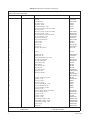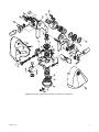
1
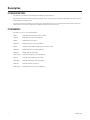
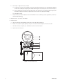
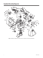
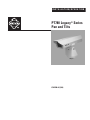
INSTALLATION/OPERATION
PT780 Legacy® Series
Pan and Tilts
C342SM-A (5/06)
Contents
Important Safety Instructions . . . . . . . . . . . . . . . . . . . . . . . . . . . . . . . . . . . . . . . . . . . . . . . . . . . . . . . . . . . . . . . . . . . . . . . . . . . . . . . . . . . . . . . . . . . .3
Description . . . . . . . . . . . . . . . . . . . . . . . . . . . . . . . . . . . . . . . . . . . . . . . . . . . . . . . . . . . . . . . . . . . . . . . . . . . . . . . . . . . . . . . . . . . . . . . . . . . . . . . . . .4
Pt780 Description . . . . . . . . . . . . . . . . . . . . . . . . . . . . . . . . . . . . . . . . . . . . . . . . . . . . . . . . . . . . . . . . . . . . . . . . . . . . . . . . . . . . . . . . . . . .4
PT780 Models . . . . . . . . . . . . . . . . . . . . . . . . . . . . . . . . . . . . . . . . . . . . . . . . . . . . . . . . . . . . . . . . . . . . . . . . . . . . . . . . . . . . . . . . . . . . . . .4
Maintenance . . . . . . . . . . . . . . . . . . . . . . . . . . . . . . . . . . . . . . . . . . . . . . . . . . . . . . . . . . . . . . . . . . . . . . . . . . . . . . . . . . . . . . . . . . . . . . . . . . . . . . . . .5
Wiring Diagrams . . . . . . . . . . . . . . . . . . . . . . . . . . . . . . . . . . . . . . . . . . . . . . . . . . . . . . . . . . . . . . . . . . . . . . . . . . . . . . . . . . . . . . . . . . . . . . . . . . . . . .7
Exploded Assembly Diagrams . . . . . . . . . . . . . . . . . . . . . . . . . . . . . . . . . . . . . . . . . . . . . . . . . . . . . . . . . . . . . . . . . . . . . . . . . . . . . . . . . . . . . . . . . . .8
List of Illustrations
1
2
3
4
5
6
Pan and Tilt Adjustments . . . . . . . . . . . . . . . . . . . . . . . . . . . . . . . . . . . . . . . . . . . . . . . . . . . . . . . . . . . . . . . . . . . . . . . . . . . . . . . . . . . . . . . . .6
PT780 Series Wiring Diagram . . . . . . . . . . . . . . . . . . . . . . . . . . . . . . . . . . . . . . . . . . . . . . . . . . . . . . . . . . . . . . . . . . . . . . . . . . . . . . . . . . . . .7
Exploded Assembly Diagram of Mechanical Parts-PT780 Series 24 VAC and 120 VAC Models . . . . . . . . . . . . . . . . . . . . . . . . . . . . . . . . . .8
Exploded Assembly Diagram of Mechanical Parts-PT780 Series 12 VDC Models . . . . . . . . . . . . . . . . . . . . . . . . . . . . . . . . . . . . . . . . . . . . .9
Exploded Assembly Diagram of Hardware-PT780 Series 24 VAC and 120 VAC Models.. . . . . . . . . . . . . . . . . . . . . . . . . . . . . . . . . . . . . . .12
Exploded Assembly Diagram of Hardware-PT780 Series 12 VDC Models . . . . . . . . . . . . . . . . . . . . . . . . . . . . . . . . . . . . . . . . . . . . . . . . . .13
List of Tables
A
B
C
2
Mechanical Parts List (Figure 3 and Figure 4) . . . . . . . . . . . . . . . . . . . . . . . . . . . . . . . . . . . . . . . . . . . . . . . . . . . . . . . . . . . . . . . . . . . . . . . .10
Mechanical Parts List (Figure 3 and Figure 4) (continued). . . . . . . . . . . . . . . . . . . . . . . . . . . . . . . . . . . . . . . . . . . . . . . . . . . . . . . . . . . . . . .11
Hardware Parts List (Figure 5 and Figure 6). . . . . . . . . . . . . . . . . . . . . . . . . . . . . . . . . . . . . . . . . . . . . . . . . . . . . . . . . . . . . . . . . . . . . . . . . .14
C342SM-A (5/06)
Important Safety Instructions
1. Installation and servicing should be done only by qualified service personnel and conform to all local codes.
2. The weight of the camera/lens and enclosure must not exceed 40 lb (18.14 kg) with 12 VDC pan and tilts or 52 lb (23.59 kg) with 24 VAC or
120 VAC pan and tilts.
3. Only use replacement parts Pelco recommends.
4. After replacing/repairing the unit’s electrical components, conduct a resistance measurement between line and exposed parts to verify the
exposed parts have not been connected to line circuitry.
5. Installation methods and materials should be capable of supporting four times the combined weight of the enclosure, pan and tilt, camera,
and lens.
The product and/or manual may bear the following marks:
This symbol indicates that dangerous voltage constituting a risk of electric shock is
present within this unit.
This symbol indicates that there are important operating and maintenance instructions
in the literature accompanying this unit.
CAUTION:
RISK OF ELECTRIC SHOCK.
DO NOT OPEN.
To reduce the risk of electrical shock, do not remove cover. No user-serviceable parts
inside. Refer servicing to qualified service personnel.
C342SM-A (5/06)
3
Description
PT780 DESCRIPTION
The PT780 Series pan and tilt units are designed for medium duty, indoor/outdoor use.
Only Legacy Series enclosures can be mounted on the pan and tilt units. These enclosures are EH4700L and EH5700L environmental enclosures
and the EH8106L pressurized enclosure.
You can easily removee the clamshell covers from the sides of the pan and tilt units to access all internal parts without having to remove the
camera enclosure. This makes servicing the units and adjusting the pan and tilt limit stops easy.
PT780 MODELS
The PT780 Series consists of the following models:
4
PT780P
Heavy-duty, indoor/outdoor pan and tilt, 120 VAC.
PT780P/PP
PT780P with preset positioning capabilities.
PT780SL
PT780P with 360° pan rotation.
PT780SL/PP
PT780SL with preset positioning capabilities.
PT780VS
Heavy-duty, indoor/outdoor, variable-speed pan and tilt, 12 VDC.
PT780VS/PP
PT780VS with preset positioning capabilities.
PT780/VSSL
PT780VS with 360° pan rotation.
PT780-VSSL/PP
PT780-VSSL with preset positioning capabilities.
PT780-24P
Heavy-duty, indoor/outdoor pan/tilt, 24 VAC.
PT780-24P/PP
PT780-24P with preset positioning capabilities.
PT780-24SL
PT780-24P with 360° pan rotation.
PT780-24SL/PP
PT780-24SL with preset positioning capabilities.
C342SM-A (5/06)
Maintenance
If you need to remove the enclosure, protect the RediLINK™ connector area against moisture, dust, dirt, etc. Failure to do so could result in a bad
connection. Also, damage to the pan and tilt unit or enclosure could occur when power is turned on.
The following servicing should be done every six months with average use.
1. Remove the PT780’s outer casing.
a.
Remove the Phillips screw on each side of the pan and tilt unit.
b.
Place your hands under the cover halves. Exert a strong, upward force to release the covers from their internal latching devices.
c.
Pull the cover halves away from the pan and tilt unit. Set the covers down or hang them by the eyelets inside the covers. (The wire
and hook on which to hang the covers is not provided.)
2. Inspect the gaskets around the cover, tilt shaft, and spindle for damage.
3. Refer to Figure 1. It shows the parts locations of the tilt assembly. Look for similar orientations of parts when adjusting the pan assembly.
4. Check the backlash adjustment.
Backlash is the slack or binding in a pan and tilt base mount. Determine backlash by lifting the maintenance assembly, grasping the base,
and wiggling it. There should not be any play or binding between the gear (A) and worm drive (B). Play or binding indicates a backlash
problem.
•
•
a.
C342SM-A (5/06)
One backlash problem involves a worm and worm gear connection loose enough to cause slipping or tight enough to cause binding.
The second involves a too-loose or too-tight chain, usually causing symptoms similar to the worm and worm gear problem–slipping or
binding.
Verify that the worm drive (B) is fully seated in the worm gear (A). If it is not:
(1)
Locate the worm-driven gear for either the pan or the tilt motor linkage. Loosen the three hex screws (F) holding the worm in
place, but leave enough thread in place to hold the assembly on the mount.
(2)
Using your thumbs, gently move the worm forward or pull the assembly back from the worm gear to either tighten or loosen the
gear spacing to the worm gear. Move the base of the pan and tilt to check the adjustment.
(3)
If you get movement in the base, press a finger down in the middle of the worm assembly. If you get no movement in the base,
use your thumb and forefinger to pull the worm assembly back until you get movement.
(4)
When the spacing is correct, tighten the hex screws. Start with the middle screw to ensure proper spacing.
(5)
Remove the screw (C) in the gear train nut (D).
(6)
Tighten the gear train nut to remove any play.
(7)
Line up the hole in the gear train nut with the nearest hole in the gear train bracket (E).
(8)
Replace the screw.
5
b.
c.
Refer to Figure 1. Adjust chain tension, if needed:
(1)
Locate the pan or tilt motor on the assembly. Loosen the hex screws (G) that hold the motor to its mounting bracket. Depending
on which motor assembly you are adjusting, there will be either three (pan) or four (tilt). (Only two screws are shown in Figure 1.)
(2)
Using a screwdriver, pry the motor down (at H) to tighten for the correct chain tension. (You should not be able to freely move the
motor with your finger, nor should it be so tight that it will not move at all as this usually leads to binding.)
(3)
Tighten the hex screws.
Using a controller, you should now be able to move the PT780 without looseness or binding. If you have any problems, contact Pelco’s
Technical Support Department.
5. Lubricate the chains. Use a Teflon® chain lubricant.
6. Replace the covers.
a.
Grasp one cover half in each hand and position the covers on each side of the pan and tilt unit.
b.
Bring the two cover halves together, aligning the two pins in one cover half with the mating holes in the other cover half.
c.
When the cover halves are together, press downward to force the covers into their latches.
d.
Replace the screws in the covers.
H
G
Figure 1. Pan and Tilt Adjustments
6
C342SM-A (5/06)
Wiring Diagrams
Figure 2. PT780 Series Wiring Diagram
C342SM-A (5/06)
7
Exploded Assembly Diagrams
Figure 3. Exploded Assembly Diagram of Mechanical Parts, PT780 Series 24 VAC and 120 VAC Models
8
C342SM-A (5/06)
9
8
10
12
11
13
17
16
60
18
19
20
21
6
22
7
23
24
63
4
14
64
15
62
41
26
25
40
27
61
46
57
53
15
51
50
14
3
59
58
6
2
29
39
61
47
1
31
49
48
44
46
33
54
45
38
34
37
42
43
21
22
36
21
35
56
55
Figure 4. Exploded Assembly Diagram of Mechanical Parts, PT780 Series 12 VDC Models
C342SM-A (5/06)
9
Table A. Mechanical Parts List (Figure 3 and Figure 4)
Refer to Figure 3 for 24 VAC and 120 VAC models.
Refer to Figure 4 for 12 VDC models.
Item
Quantity
Description
Part Number
1
2
3
4
1
2
2
1
5
1
9064003COMP
PT180410000
9064010COMP
5708008
1758008
9068102
1758009
6
1
7
1
8
9
10
11
12
13
14
1
1
1
1
1
2
4
2**
4
2**
1
1
1
1
1
4
3
2
1
1
1
1
Cover, pan side
Ball stud
Ball stud bracket
Pan motor, 24 VAC
Pan motor, 120 VAC
Pan motor gearhead, 12 VDC
Pan motor gearhead, 24 VAC and 120 VAC
Not used, 12 VDC
Pan motor sprocket, 24 VAC amd 120 VAC
Pan motor sprocket, 12 VDC
Pan motor bracket, 24 VAC and 120 VAC
Pan motor bracket, 12 VDC
Tilt preset potentiometer
Tilt potentiometer bracket
Gear, 32 teeth
Gear, 52 teeth
Tilt limit ring
Tilt limit stop
Actuator, with insulator
Switch
SWI1SM1
Upright, pan side
Bushing, pan side
26-pin, subminiature, D-type socket
Tilt shaft connector guide
Tilt shaft feed-through
Thrust washer, .030”
Thrust bearing
Thrust washer, .060”
Bronze bushing
Cross-brace uprights
Upright, tilt side
Worm gear, 40 teeth
MF80-9060-002G
PT250010004
COND226S
9004015COMP
9004000COMP
90010002
90010001
90010024
90010006
9064008COMP
MF80-9060+001C
90010009
9004024COMP***
9004025COMP****
90010028
9004007COMP
5808002
1758008
9068101
5808003
1758009
15
16
17
18
19
20
21
22
23
24
25
26
27
28
29
1
1
1
30
1
31
1
32
1
33
1
1
34
35
1
1
*PP models only
**All SL models
10
Sprocket, 24 VAC and 120 VAC
Sprocket, 12 VDC
Tilt motor, 24 VAC
Tilt motor, 120 VAC
Tilt motor with earhead, 12 VDC
Tilt motor gearhead, 24 VAC
Tilt motor gearhead, 120 VAC
Not used, 12 VDC
Tilt motor bracket, 24 VAC and 120 VAC
Tilt motor bracket, 12 VDC
Sprocket, 24 VAC
Sprocket, 120 VAC
Sprocket, 12 VDC
Circuit board assembly, 24 VAC
Circuit board assembly, 120 VAC
Circuit board assembly, 12 VDC
Cover, tilt side
Pan spindle
580401ACOMP
9004007COMP
9064006COMP
9064060COMP
POTP010.0K*
9064012COMP*
28010017*
28010016*
9004012COMP
1554050COMP
SWIJS138B
9064005COMP
9064059COMP
5804022COMP
17512004
9004007COMP
PA05-0009-01B0
PA05-0009-03B0
PA05-0009-0280
9064004COMP
9004030COMP
*** SL/PP models only
**** Non-360° PP models
C342SM-A (5/06)
Table A. Mechanical Parts List (Figure 3 and Figure 4) (Continued)
Item
Quantity
Description
Part Number
36
37
38
39
40
3
1
1
1
1
Pan limit stop
Bronze bushing
Base
Pan limit pin
Slip ring
41
1
Preset gear, pan spindle
42
43
44
1
1
1
Pan potentiometer bracket
Gear, 56 teeth
Pan preset potentiometer
45
46
47
48
49
50
51
52
2
4
53
54
55
4
2
2
1
1
1
1
2
1
56
1
Gear train nut
Bronze bushing
Thrust washer
Thrust bearing
Worm
Gear train bracket
3-position bar nut
Sprocket, 24 VAC and 120 VAC
Sprocket, 12 VDC
Pan spindle nut
Ball stud receiver
Grommet, 3/8” ID
Grommet, 1/4” ID
Wire clamp
57
58
59
60
61
62
63
64
2
2
1
1
1
1
1
1
Eyelet service bracket
Snap ring
Pan limit switch bracket
Wave spring
Grommet
Unthreaded backup plate
Threaded backup plate
Worm gear
58010006*****
90010029
MF01-9060-003J
1554049COMP*****
250010000***
28010000******
9004017COMP***
9004022COMP****
9004008COMP*
90010020*
POTDARM010.0K****
POTP010.0K****
9004009COMP
5806005
5806003
5806002
90010008
9004005COMP
9004006COMP
PT18004003COMP
9004007COMP
9004019COMP
90010030
GRO2175
GRO2170**
9004020COMP*****
9004021COMP**
9004023COMP
15510000*****
1554051COMP*****
90010017
GRO2172N*****
9064015COMP
9064014COMP
90010009
Pan chain assembly, 29 pitch, 24 VAC and 120 VAC
Pan chain assembly, 32 pitch, 12 VDC
Tilt chain assembly, 35 pitch, 24 VAC and 120 VAC
Tilt chain assembly, 28 pitch, 12 VDC
2-position plastic connector
3-position plastic connector
6-position plastic connector
Cover labels
Dust protector, 26-pin, subminiature, D-type socket
37-pin connector plug (installed on cable)
Connector pins
Cable connector clamp
37-pin connector socket assembly (loose equipment)
9061002ASSY
9061013ASSY
9061003ASSY
9061008ASSY
CON640428-2
CON640428-3G
CON640428-6
LBL19000
90010025
CN54-2209-2737
CON66102-7
CON206138-1
CONA37S
The following items are not shown:
65
1
66
1
67
68
69
70
71
72
73
74
75
1
6
1
2
1
1
37
1
1
*PP models only
**All SL models
***SL/PP models only
C342SM-A (5/06)
**** Non-360° PP models
***** Not on SL models
****** SL models
11
K
G
E
E
I
H
I
L
J
FF
J
EE
F
M
F
A
B
C
D
PP
S
T
AA
Q
N
NN
J
O
W
N
M
BB
EE
CC
E
F
Q
I
J
J
J
W
R
S
J
T
BB
W
W
J
P
DD
E
KK
T
F
JJ
II
HH
D*
C*
B*
A*
Z
S
Y
GG
X
LL
V
U
MM
I
J
Figure 5. Exploded Assembly Diagram of Hardware, PT780 Series 24 VAC and 120 VAC Models
12
C342SM-A (5/06)
I
K
G
I
H
J
L
J
FF
E
EE
F
E
F
M
B
F
A
PP
S
T
AA
J
NN
D
N
W
N
EE
CC
M
BB
E
BB
J
F
I
J
J
W
R
S
J
T
BB
W
W
J
B
A
P
F
DD
Z
E
F
T
S
Y
GG
X
LL
V
U
MM
J
I
Figure 6. Exploded Assembly Diagram of Hardware, PT780 Series 12 VDC Models
C342SM-A (5/06)
13
Table B. Hardware Parts List (Figure 5 and Figure 6)
Refer to Figure 5 for 24 VAC and 120 VAC models.
Refer to Figure 6 for 12 VDC models.
Item
Quantity
Description
Part Number
A
4
8
4
4
8
4
4
8
Screw, 6-32 x 2 1/2”, pan head, Phil, 24 VAC
Screw, 8-32 x 2 1/2”, pan head, Phil, 120 VAC
Screw, 10-32 x 1/2”, pan head, Phil, 12 VDC
Flat washer, 24 VAC
Flat washer, 120 VAC
Flat washer, 12 VDC
Split lock washer, #6, 24 VAC
Split lock washer, #8, 120 VAC
Not used, 12 VDC
Hex nut, 6-32, 24 VAC
Hex nut, 8-32, 120 VAC
Not used, 12 VDC
Allen screw, 10-32 x 3/8”, 24 VAC and 120 VAC
Allen screw, 10-32 x 3/8”, 12 VDC
Split lock washer, #10, 24 VAC and 120 VAC
Split lock washer, #10, 12 VDC
Screw, 2-56 x 3/8”, pan head, Phillips
Internal star washer, #2
Screw, 4-40 x 3/8”, pan head, Phillips
Internal star washer, #4
Screw, 8-32 x 1/4”, pan head, Phillips
Internal star washer, #8
Screw, 2-56 x 7/16”, pan head, Phillips
Screw, 6-32 x 1/2”, flat head, Phillips
Bolt, 1/4-20 x .625”, flat head, Phillips
Screw, 4-40 x 5/8”, pan head, Phillips
Roll pin (Not shown in Figure 15)
Allen bolt, 1/4-20 x 12”
Flat washer, 1/4
Split lock washer, 1/4
Screw, 10-32 x .875”, gray
Thread sealing washer
Screw, 4-40 x .250”, pan head, Phillips
Screw, 6-32 x .375”, pan head, Phillips
Allen bolt, 1/4-20 x 3/4”
Bolt, 1/4-20 x 3/4”, flat head, Phillips
Self-tapping screw, 6-32
Roll pin
Allen screw, 4-40 x .250”
Dowel pin
Cover gasket
Tilt shaft gasket
Set screw, 6-32 x 3/16”
Screw, 8-32 x 2 1/2”, pan head, Phillips, 24 VAC only
Flat washer, 2 VAC only
Split lock washer, #8, 24 VAC only
Hex nut, 8-32, 24 VAC only
Spindle cover gasket
Spindle mount gasket
Screw, 10-32 x 3/4”, pan head, Phillips
Allen bolt, 1/4-20 x .625”
ZH6-32X2.50SPP
ZH8-32X2.50CPS
ZH10-32X.500SPP
ZH932X1.75X130
ZH932X1.75X130
ZH240X436X60C
ZH6LWSSL
ZH8LWSSL
B
C
D
4
8
E
12
11
12
15
3
3
9
25
2
2
8
12
2
2
2
6
11
11
2
2
14
2
3
3
2
2
2
2
1
1
1
4
4
4
4
1
1
3
2
F
G
H
I
J
K
L
M
N
O
P
Q
R
S
T
U
V
W
X
Y
Z
AA
BB
CC
DD
EE
FF
GG
HH
II
JJ
KK
LL
MM
NN
PP
14
ZH6-32NUTSH
ZH8-32NUTSH
ZH10-32X.375SSS
ZH10LWSSL
ZH2-56X.375SRS
ZH2LWSIS
ZH4-40X.375SPP
ZH4LWSIS
ZH8-32X.250SPP
ZH8LWSIS
ZH2-56X.437SPP
ZH6-32X.500FPF
ZH1/420X.625SFS
ZH4-40X.625SPP
ZHPIN3/32X1/2R
ZH1/420X1.50SS
ZH260X562X65C
ZH1/4LWSSL
ZH10-32X.875GRY
PS3010002
ZH4-40X.250SPP
ZH6-32X.375SPP
ZH1/420X.750SS
ZH1/420X.750SFS
ZH6-SAX.250CPP
ZHPIN3/32X1/2R
ZH4-40X.250SS
90010004
GS05-1102-0001
GS05-0102-002A
ZH6-32X.187S
ZH8-32X2.50CPS
ZH932X1.75X130
ZH8LWSSL
ZH8-32NUTSH
90010003
90010012
ZH10-32X.750SPP
ZH1/420X.625CS
C342SM-A (5/06)
PRODUCT WARRANTY AND RETURN INFORMATION
WARRANTY
Pelco will repair or replace, without charge, any merchandise proved defective in material or
workmanship for a period of one year after the date of shipment.
Exceptions to this warranty are as noted below:
• Five years on FR/FT/FS Series fiber optic products and TW3000 Series unshielded twisted
pair transmission products.
• Three years on Genex ® Series products (multiplexers, server, and keyboard).
• Three years on Camclosure ® and fixed camera models, except the CC3701H-2,
CC3701H-2X, CC3751H-2, CC3651H-2X, MC3651H-2, and MC3651H-2X camera models,
which have a five-year warranty.
• Three years on PMCL200/300/400 Series LCD monitors.
• Two years on standard motorized or fixed focal length lenses.
• Two years on Legacy ®, CM6700/CM6800/CM9700 Series matrix, and DF5/DF8 Series
fixed dome products.
®
®
™
• Two years on Spectra , Esprit , ExSite , and PS20 scanners, including when used in
continuous motion applications.
• Two years on Esprit ® and WW5700 Series window wiper (excluding wiper blades).
• Two years (except lamp and color wheel) on Digital Light Processing (DLP ®) displays.
The lamp and color wheel will be covered for a period of 90 days. The air filter is not
covered under warranty.
• Eighteen months on DX Series digital video recorders, NVR300 Series network video
recorders, and Endura ™ Series distributed network-based video products.
• One year (except video heads) on video cassette recorders (VCRs). Video heads will be
covered for a period of six months.
• Six months on all pan and tilts, scanners or preset lenses used in continuous motion
applications (that is, preset scan, tour and auto scan modes).
Pelco will warrant all replacement parts and repairs for 90 days from the date of Pelco
shipment. All goods requiring warranty repair shall be sent freight prepaid to Pelco, Clovis,
California. Repairs made necessary by reason of misuse, alteration, normal wear, or accident
are not covered under this warranty.
Pelco assumes no risk and shall be subject to no liability for damages or loss resulting from
the specific use or application made of the Products. Pelco’s liability for any claim, whether
based on breach of contract, negligence, infringement of any rights of any party or product
liability, relating to the Products shall not exceed the price paid by the Dealer to Pelco for
such Products. In no event will Pelco be liable for any special, incidental or consequential
damages (including loss of use, loss of profit and claims of third parties) however caused,
whether by the negligence of Pelco or otherwise.
The above warranty provides the Dealer with specific legal rights. The Dealer may also have
additional rights, which are subject to variation from state to state.
If a warranty repair is required, the Dealer must contact Pelco at (800) 289-9100 or
(559) 292-1981 to obtain a Repair Authorization number (RA), and provide the following
information:
1. Model and serial number
2. Date of shipment, P.O. number, Sales Order number, or Pelco invoice number
3. Details of the defect or problem
If there is a dispute regarding the warranty of a product which does not fall under the
warranty conditions stated above, please include a written explanation with the product
when returned.
Method of return shipment shall be the same or equal to the method by which the item was
received by Pelco.
RETURNS
In order to expedite parts returned to the factory for repair or credit, please call the factory at
(800) 289-9100 or (559) 292-1981 to obtain an authorization number (CA number if returned
for credit, and RA number if returned for repair).
All merchandise returned for credit may be subject to a 20% restocking and refurbishing
charge.
Goods returned for repair or credit should be clearly identified with the assigned CA or RA
number and freight should be prepaid. Ship to the appropriate address below.
If you are located within the continental U.S., Alaska, Hawaii or Puerto Rico, send goods to:
Service Department
Pelco
3500 Pelco Way
Clovis, CA 93612-5699
If you are located outside the continental U.S., Alaska, Hawaii or Puerto Rico and are
instructed to return goods to the USA, you may do one of the following:
If the goods are to be sent by a COURIER SERVICE, send the goods to:
Pelco
3500 Pelco Way
Clovis, CA 93612-5699 USA
If the goods are to be sent by a FREIGHT FORWARDER, send the goods to:
Pelco c/o Expeditors
473 Eccles Avenue
South San Francisco, CA 94080 USA
Phone: 650-737-1700
Fax: 650-737-0933
This equipment contains electrical or electronic components that must be recycled properly to comply with Directive 2002/96/EC of the European Union
regarding the disposal of waste electrical and electronic equipment (WEEE). Contact your local dealer for procedures for recycling this equipment.
REVISION HISTORY
Manual #
C342SM
C342SM-A
Date
12/98
5/06
Comments
Original version.
Updated parts list. Reformatted manual.
Pelco, the Pelco logo, Camclosure, Esprit, Genex, Legacy, and Spectra are registered trademarks of Pelco.
Endura, ExSite, and RediLINK are trademarks of Pelco.
DLP is a registered trademark of Texas Instruments, Inc.
Teflon is a registered trademark of E.I. du Pont de Nemours and Company.
©Copyright 2006, Pelco. All rights reserved.
Worldwide Headquarters
3500 Pelco Way
Clovis, California 93612 USA
USA & Canada
Tel: 800/289-9100
Fax: 800/289-9150
International
Tel: 1-559/292-1981
Fax: 1-559/348-1120
www.pelco.com
ISO9001
United States
| Canada | United Kingdom | The Netherlands | Singapore | Spain | Scandinavia | France | Middle East