1
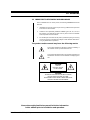
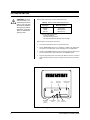
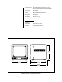
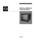
®
PELCO
®
PMC14F
14-Inch Color Monitor
Installation/
Operation Manual
C1950M (10/98)
Pelco • 3500 Pelco Way • Clovis, CA 93612-5699 USA • www.pelco.com
In North America and Canada: Tel (800) 289-9100 or FAX (800) 289-9150
International Customers: Tel (1-559) 292-1981 or FAX (1-559) 348-1120
CONTENTS
Section
Page
1.0 GENERAL .................................................................................................. 3
1.1 IMPORTANT SAFEGUARDS AND WARNINGS ............................... 3
1.2 UNPACKING INSTRUCTIONS .......................................................... 4
2.0 DESCRIPTION .......................................................................................... 5
2.1 MODELS ............................................................................................ 5
2.2 RATINGS ........................................................................................... 5
3.0 INSTALLATION .......................................................................................... 6
4.0 OPERATION .............................................................................................. 8
4.1 FRONT PANEL CONTROLS ............................................................. 8
4.2 PASSIVE LOOPING .......................................................................... 8
5.0 MAINTENANCE ......................................................................................... 9
6.0 SPECIFICATIONS ....................................................................................10
7.0 WARRANTY AND RETURN INFORMATION ........................................... 12
LIST OF ILLUSTRATIONS
Figure
1
2
3
4
5
6
Page
Rear Panel Connections ....................................................................6
One Monitor with External Video Equipment ..................................... 7
Monitor Looping with External Video Equipment ............................... 7
S-VHS Video (Y/C) Input Connections .............................................. 7
Front Panel Controls .......................................................................... 8
PMC14F Series Dimension Drawing ................................................ 11
LIST OF TABLES
Table
A
Page
Video Coaxial Cable Requirements ................................................... 6
REVISION HISTORY
Manual #
C1950M
2
Date
Comments
7/98
Original version.
10/98
Removed PMC14F-X model and revised descriptions of
power cords.
Pelco Manual C1950M (10/98)
1.0 GENERAL
1.1 IMPORTANT SAFEGUARDS AND WARNINGS
Prior to installation and use of this product, the following WARNINGS should be
observed.
1.
Installation and servicing should only be done by qualified service personnel
and conform to all local codes.
2.
Unless the unit is specifically marked as a NEMA Type 3, 3R, 3S, 4, 4X ,6 or
6P enclosure, it is designed for indoor use only and it must not be installed
where exposed to rain and moisture.
3.
Do not attempt to service this CCTV product yourself as opening or removing
covers may expose you to dangerous voltages or other hazards. Refer all servicing to qualified service personnel.
The product and/or manual may bear the following marks:
This symbol indicates that dangerous voltage constituting a
risk of electric shock is present within this unit.
This symbol indicates that there are important operating and
maintenance instructions in the literature accompanying this
unit.
CAUTION:
RISK OF
ELECTRIC SHOCK.
DO NOT OPEN.
CAUTION:
TO REDUCE THE RISK OF ELECTRICAL SHOCK,
DO NOT REMOVE COVER. NO USERSERVICEABLE PARTS INSIDE. REFER SERVICING
TO QUALIFIED SERVICE PERSONNEL.
Please thoroughly familiarize yourself with the information
in this manual prior to installation and operation.
Pelco Manual C1950M (10/98)
3
1.2 UNPACKING INSTRUCTIONS
Unpack and inspect all parts carefully.
Be sure to save the shipping carton and any inserts. They are the safest material in
which to make future shipments.
If an item appears to have been damaged in shipment, replace it properly in its
carton and contact the factory at 1-800-289-9100 or 1-559-292-1981 for a replacement. (International customers fax 1-559-348-1120 for authorization and instructions.)
If an item needs to be returned to the factory for repair, consult the WARRANTY
AND RETURN section of this manual for instructions.
The following parts are supplied:
1
1
4
Color monitor with two power cords
Installation/Operation Manual
Pelco Manual C1950M (10/98)
2.0 DESCRIPTION
The PMC14F is a high-resolution color video monitor that can be used in desktop
applications or rack mounted using the optional RMA14F rack mount kit. The monitor supports both NTSC and PAL video, as well as 120 VAC and 230 VAC input
power. An automatic switching system makes all the necessary changes for adapting to the required formats. Manual selection is not required.
The PMC14F features audio input and output, and has a steel housing and front
panel controls. The S-VHS high-resolution video (460 horizontal lines at center)
and digital comb filter add to the superior picture quality.
2.1 MODELS
PMC14F
Color monitor, 14-inch (35.56 cm) picture display, 110-240 VAC,
50/60 Hz, NTSC or PAL, auto select; supplied with two power
cords: one for 120 VAC and one for 230 VAC
(CE, UL, C-UL)
2.2 RATINGS
•
•
Pelco Manual C1950M (10/98)
NEMA Type 1
IP 30
5
3.0 INSTALLATION
CAUTION: Do not install this monitor in a location having excessive
heat or in any way that
obstructs the ventilation
openings in the cabinet.
Premature component
failure or cabinet damage may result.
Refer to Table A for the type of video coaxial cable to use.
Table A. Video Coaxial Cable Requirements
Cable Type*
Maximum Distance
RG59/U
RG6/U
RG11/U
750 ft (229 m)
1,000 ft (305 m)
1,500 ft (457 m)
* Minimum cable requirements:
75 ohms impedance
All-copper center conductor
All-copper braided shield with 95% braid coverage
Refer to Figure 1 for rear panel connections.
1.
Connect the equipment as shown in Figures 2 through 4.
2.
Set the IMPEDANCE switch on the monitor(s) to HIGH if the VIDEO OUT
connection is used. Otherwise, set the switch(es) in the 75-OHM position.
3.
Set the S-VHS/CAMERA switch on the monitor(s) to S-VHS if the S-VHS input
jack is used. Otherwise, set the switch(es) in the CAMERA position.
4.
Plug the appropriate power cord into the AC INLET connection on the rear
panel of the monitor (refer to Figure 1). Plug the other end into a power receptacle.
VIDEO OUT
JACK (BNC)
AC
INLET
CAMERA INPUT
JACK (BNC)
AUDIO OUT
JACK (RCA)
IMPEDANCE
SWITCH
(HIGH/75Ω)
S-VHS/CAMERA
SWITCH
S-VHS
JACK
AUDIO IN
JACK (RCA)
Figure 1. Rear Panel Connections
6
Pelco Manual C1950M (10/98)
CAMERA
VIDEO OUT CAMERA INPUT
VCR
OUT
IMPEDANCE
AUDIO
HIGH 75Ω S-VHS CAMERA
IN
Figure 2. One Monitor with External Video Equipment
MAXIMUM OF THREE MONITORS
VCR
VIDEO OUT CAMERA INPUT
IMPEDANCE
AUDIO
HIGH 75Ω S-VHS CAMERA
OUT
OUT
OUT
IMPEDANCE
VIDEO OUT CAMERA INPUT
VIDEO OUT CAMERA INPUT
AUDIO
HIGH 75Ω S-VHS CAMERA
IN
IN
IMPEDANCE
AUDIO
HIGH 75Ω S-VHS CAMERA
IN
CAMERA
Figure 3. Monitor Looping with External Video Equipment
VCR
OUT
S-VHS
S-VHS CAMERA
AUDIO
S-VHS OUT AUDIO OUT
IN
Figure 4. S-VHS Video (Y/C) Input Connections
Pelco Manual C1950M (10/98)
7
4.0 OPERATION
4.1 FRONT PANEL CONTROLS
Refer to Figure 5 for front panel controls.
1.
Press the POWER switch to turn the monitor on. The power LED lamp above
the switch will illuminate when the power is applied.
2.
Adjust the VOLUME control for the desired audio level. Turn the control clockwise to increase and counterclockwise to decrease.
3.
Adjust the CONT. control for the desired overall contrast. Proper adjustment
will allow maximum gradations between the darkest and lightest picture contrast. Turn the control clockwise to increase and counterclockwise to decrease.
4.
Adjust the BRIGHT control for the desired overall display brightness. This control is also useful to compensate for differences in surrounding area lighting.
Turn the control clockwise to increase and counterclockwise to decrease.
5.
Adjust the COLOR control to set the color saturation level. Turn the control
clockwise to increase and counterclockwise to decrease.
6.
Adjust the SHARP control to obtain the clearest picture.
7.
Adjust the TINT control for the proper color phase or flesh tones. When turned
clockwise, the skin tone becomes greenish. When turned counterclockwise, skin
tone becomes reddish.
4.2 PASSIVE LOOPING
Passive looping is accomplished when two or three monitors are connected in series (see Figure 3) and a looping signal is sent through the IN and OUT connectors
of one monitor to the next in the series. Unless you want to view the monitor(s),
none of them need to be turned on for passive looping to function.
POWER
LED LAMP
TINT
SHARP
COLOR BRIGHT
CONT. VOLUME POWER
Figure 5. Front Panel Controls
8
Pelco Manual C1950M (10/98)
5.0 MAINTENANCE
If the quality of the picture is poor and cannot be improved by making adjustments
on the front control panel, inspect all system connections and cable runs.
To reduce the risk of electrical shock, do not remove the cover or the back. No userserviceable parts are inside. Refer servicing to qualified personnel or contact the
Pelco Customer Department for assistance. Refer to Section 7.0 for warranty and
return information.
Clean the cabinet with a cloth slightly dampened with mild household detergent
only. Use a soft cloth for drying. Some household aerosol sprays, cleaning agents,
solvents, or polishes may damage the cabinet finish. Never use strong solvents
such as thinner or benzene.
Pelco Manual C1950M (10/98)
9
6.0 SPECIFICATIONS
ELECTRICAL
Input Voltage:
110-240 VAC, 50/60 Hz
Power
Consumption:
60 watts
Horizontal
Resolution:
460 lines (center)
380 lines (corners)
Picture Tube:
14 inches (35.56 cm) measured diagonally
Effective
Picture Size:
Height
Width
8.27 inches (21.0 cm)
11.0 inches (28.0 cm)
Input Signal:
Terminals:
Video Input
Level /
Impedance
Video Output
Level /
Impedance
Audio Input
Level /
Impedance
Audio Output
Level /
Impedance
Subcarrier
Frequency
Sync Range:
Composite video, negative sync
Y: 1.0 Vp-p
C: 0.286 Vp-p
1.0 Vp-p/75 ohms
1.0 Vp-p/75 ohms
0.3 Vrms/25K ohms (over)
0.3 Vrms/4.7K ohms (under)
3.579549 MHz ±200 Hz
4.433619 MHz ±200 Hz
at room temperature
High Voltage:
23.5 kV ±500 V
Convergence:
<1.0 mm (at center of picture)
<1.4 mm (at corners of picture)
Brightness:
More than 250 lux in 100% white signal
picture at center
GENERAL
Connectors
Camera Input/
Video Output:
S-VHS Input:
Audio Input/
Output:
10
BNC
4-pin mini DIN
RCA
Pelco Manual C1950M (10/98)
AC Power Cord:
One power cord with grounded plug for 120 VAC
One “Euro”-style grounded power cord for 230 VAC
Construction:
Steel cabinet
Finish:
Black with black bezel around screen
Dimensions:
See Figure 6
Unit Weight:
26.75 lb (12.13 kg)
Shipping Weight:
32 lb (14.51 kg)
ENVIRONMENTAL
Operating
Temperature:
32° to 106°F (0° to 41°C)
Humidity:
0% to 90% (non-condensing)
(Design and product specifications subject to change without notice.)
13.00
(33.02)
13.75
(34.93)
14.50
(36.83)
15.44
(39.22)
Figure 6. PMC14F Series Dimension Drawing
Pelco Manual C1950M (10/98)
11
7.0 WARRANTY AND RETURN INFORMATION
WARRANTY
Pelco will repair or replace, without charge, any merchandise proved defective in material or
workmanship for a period of one year after the date of shipment.
Exceptions to this warranty are as noted below:
• Five years on FT/FR8000 Series fiber optic products.
• Three years on Genex® Series products (multiplexers, server, and keyboard).
• Three years on Camclosure® and fixed camera models, except the CC3701H-2, CC3701H-2X,
CC3751H-2, CC3651H-2X, MC3651H-2, and MC3651H-2X camera models, which have a fiveyear warranty.
• Two years on standard motorized or fixed focal length lenses.
• Two years on Legacy®, CM6700/CM6800/CM9700 Series matrix, and DF5/DF8 Series fixed
dome products.
• Two years on Spectra®, Esprit®, ExSite™, and PS20 scanners, including when used in
continuous motion applications.
• Two years on Esprit® and WW5700 Series window wiper (excluding wiper blades).
• Eighteen months on DX Series digital video recorders, NVR300 Series network video
recorders, and Endura ™ Series distributed network-based video products.
• One year (except video heads) on video cassette recorders (VCRs). Video heads will be
covered for a period of six months.
• Six months on all pan and tilts, scanners or preset lenses used in continuous motion applications
(that is, preset scan, tour and auto scan modes).
Pelco will warrant all replacement parts and repairs for 90 days from the date of Pelco shipment.
All goods requiring warranty repair shall be sent freight prepaid to Pelco, Clovis, California. Repairs
made necessary by reason of misuse, alteration, normal wear, or accident are not covered under
this warranty.
Pelco assumes no risk and shall be subject to no liability for damages or loss resulting from the
specific use or application made of the Products. Pelco’s liability for any claim, whether based on
breach of contract, negligence, infringement of any rights of any party or product liability, relating
to the Products shall not exceed the price paid by the Dealer to Pelco for such Products. In no event
will Pelco be liable for any special, incidental or consequential damages (including loss of use, loss
of profit and claims of third parties) however caused, whether by the negligence of Pelco or
otherwise.
The above warranty provides the Dealer with specific legal rights. The Dealer may also have
additional rights, which are subject to variation from state to state.
If a warranty repair is required, the Dealer must contact Pelco at (800) 289-9100 or (559) 292-1981
to obtain a Repair Authorization number (RA), and provide the following information:
1. Model and serial number
2. Date of shipment, P.O. number, Sales Order number, or Pelco invoice number
3. Details of the defect or problem
If there is a dispute regarding the warranty of a product which does not fall under the warranty
conditions stated above, please include a written explanation with the product when returned.
Method of return shipment shall be the same or equal to the method by which the item was received
by Pelco.
RETURNS
Pelco, the Pelco logo, Camclosure, Esprit,
Genex, Legacy, and Spectra are registered
trademarks of Pelco.
Endura and ExSite are trademarks of Pelco.
© Copyright 1998, Pelco. All rights reserved.
12
In order to expedite parts returned to the factory for repair or credit, please call the factory at (800)
289-9100 or (559) 292-1981 to obtain an authorization number (CA number if returned for credit,
and RA number if returned for repair).
All merchandise returned for credit may be subject to a 20% restocking and refurbishing charge.
Goods returned for repair or credit should be clearly identified with the assigned CA or RA number
and freight should be prepaid. Ship to the appropriate address below.
If you are located within the continental U.S., Alaska, Hawaii or Puerto Rico, send goods to:
Service Department
Pelco
3500 Pelco Way
Clovis, CA 93612-5699
If you are located outside the continental U.S., Alaska, Hawaii or Puerto Rico and are instructed
to return goods to the USA, you may do one of the following:
If the goods are to be sent by a COURIER SERVICE, send the goods to:
Pelco
3500 Pelco Way
Clovis, CA 93612-5699 USA
If the goods are to be sent by a FREIGHT FORWARDER, send the goods to:
Pelco c/o Expeditors
473 Eccles Avenue
South San Francisco, CA 94080 USA
Phone: 650-737-1700
Fax: 650-737-0933
Pelco Manual C1950M (10/98)