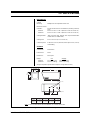
1
®
EH100 Series
Indoor Enclosure
Installation/Operation Manual
C1464M (6/97)
Pelco • 3500 Pelco Way, Clovis, CA 93612-5699 • USA • www.pelco.com
In North America and Canada: Tel (800) 289-9100 • FAX (800) 289-9150
International Customers: Tel (1-559) 292-1981 or FAX (1-559) 348-1120
CONTENTS
Section
Page
1.0 GENERAL .................................................................................................. 1
1.1 IMPORTANT SAFEGUARDS AND WARNINGS ............................... 1
2.0 DESCRIPTION .......................................................................................... 2
2.1 MODELS ............................................................................................ 2
3.0 INSTALLATION .......................................................................................... 3
4.0 MAINTENANCE ......................................................................................... 4
5.0 SPECIFICATIONS ..................................................................................... 5
6.0 WARRANTY AND RETURN INFORMATION ............................................ 6
LIST OF ILLUSTRATIONS
Figure
1
Page
EH100 Dimension Drawing ................................................................ 5
REVISION HISTORY
ii8
Manual #
Date
Comments
C1464M
6/97
Original version.
Pelco Manual C1464M (6/97)
1.0 GENERAL
1.1 IMPORTANT SAFEGUARDS AND WARNINGS
Prior to installation and use of this product, the following WARNINGS should be
observed.
1.
Installation and servicing should only be done by Qualified Service Personnel
and conform to all Local codes.
2.
Unless the unit is specifically marked as a NEMA Type 3, 3R, 3S, 4, 4X, 6, or
6P enclosure, it is designed for indoor use only and it must not be installed
where exposed to rain and moisture.
3.
Only use replacement parts recommended by Pelco.
4.
After replacement/repair of this unit’s electrical components, conduct a resistance measurement between line and exposed parts to verify the exposed
parts have not been connected to line circuitry.
5.
The installation method and materials should be capable of supporting four
(4) times the weight of the enclosure, pan/tilt, camera and lens combination.
The product and/or manual may bear the following marks:
This symbol indicates that dangerous voltage constituting a
risk of electric shock is present within this unit.
This symbol indicates that there are important operating and
maintenance instructions in the literature accompanying this
unit.
CAUTION:
RISK OF
ELECTRIC SHOCK.
DO NOT OPEN.
CAUTION:
TO REDUCE THE RISK OF ELECTRICAL SHOCK,
DO NOT REMOVE COVER. NO USERSERVICEABLE PARTS INSIDE. REFER SERVICING
TO QUALIFIED SERVICE PERSONNEL.
Please thoroughly familiarize yourself with the information
in this manual prior to installation and operation.
Pelco Manual C1464M (6/97)
1
2.0 DESCRIPTION
The EH100 Series are low-cost, light-duty, indoor camera enclosures designed for
use with various cameras on the market. These enclosures will accommodate fixed
focal length lenses or motorized zoom lenses, with or without auto-iris operation.
All aluminum construction and rugged powder-coated surfaces make the EH100
Series a lightweight, attractive camera enclosure for most indoor applications.
The simple, interlocking clam-shell design with removable housing provides a fast,
simple installation. Once installed, access to camera and lens only requires removal of one (1) tamper proof screw.
The EH100 Series enclosures have an adjustable camera sled that, when installed
upside down, can also serve as an elevation block.
A Ø .875-inch knockout on the base of the enclosure provides the opening for all
cabling or a 0.5-inch conduit connection.
2.1 MODELS
2
EH100-8
Indoor enclosure, 7.50" (19.05 cm) maximum length for camera, lens and cable connections
EH100-10
Indoor enclosure, 9.50" (24.13 cm) maximum length for camera, lens and cable connections
Pelco Manual C1464M (6/97)
3.0 INSTALLATION
Installation of all EH100 Series camera enclosures requires two (2) 1/4-20 x 1/2
inch screws (not supplied). If you are using a mount, be sure that the mount is
capable of supporting the combined weight of the camera/lens and enclosure.
A 1/4-20 x .375 inch Phillips pan head screw is provided to mount the camera to the
camera sled.
Required Tools:
•
•
Phillips head screw driver
1/4 inch tamper-proof socket wrench
To install the camera/lens, complete the following instructions:
Pelco Manual C1464M (6/97)
1.
Remove the tamper-proof screw from the back of the enclosure and separate
the base from the housing.
2.
Remove the knockout from the base.
3.
Remove the camera sled by first loosening the two screws and sliding the
sled to the large openings.
4.
Depending on the application, perform the following steps in the order that
best suits the installation.
a.
Attach the camera to the sled using the 1/4-20 screw that came in the
package. If your camera has a low optical centerline or a large diameter
lens you may want to attach the camera to the sled so that the bend in
the sled is up.
b.
Attach the enclosure base to the mount using the screws that were provided with the mount.
c.
Slide the camera/camera sled assembly onto the base, make all connections to the camera, and adjust the assembly to fit within the enclosure when assembled. Tighten the screws on the camera sled.
d.
Adjust camera/lens, if necessary.
e.
Replace the housing and tighten the tamper-proof screw.
3
4.0 MAINTENANCE
Clean the window regularly with a mild nonabrasive detergent in water and with a
soft cloth to help maintain picture clarity.
4
Pelco Manual C1464M (6/97)
5.0 SPECIFICATIONS
MECHANICAL
Camera
Mounting:
Multiple holes on adjustable camera sled
Maximum Camera
Size BNC:
Accepts camera and lens combinations (including connector)
up to:
EH100-8
3.50" W x 2.75" H x 7.50" L (8.89 cm x 6.99 cm x 19.05 cm)
EH100-10
3.50" W x 2.75" H x 9.50" L (8.89 cm x 6.99 cm x 24.13 cm)
Viewing Window:
.188" (4.76 mm) thick, optically clear impact-resistant MRS
coated Lexan (UL 94HB rated)
Viewing Area:
2.25" H x 2.31" W (5.72 cm x 5.87 cm)
Cable Entry Hole:
Ø .875-inch (2.22 cm) knockout; will accept 0.5-inch (1.27 cm)
conduit fitting
GENERAL
Construction:
All-aluminum
Environment:
Indoor
Dimensions:
See Figure 1
Weight:
EH100-8
EH100-10
Unit
1 lb 4 oz (0.57 kg)
1 lb 8 oz. (0.68 kg)
Shipping
2 lb 4 oz (1.02 kg)
2 lb 8 oz (1.13 kg)
(Design and product specifications subject to change without notice.)
4.00 (10.16)
A
2.31
(5.87)
.25 (.635)
3.63
(9.22)
2.25
(5.72)
B
1/4-20 (2 PLCS)
2.00
(5.08)
C
D
T
A
B
L
Ø .875 (2.222)
E
MODEL
A
B
C
EH100-8
9.25 (23.50)
8.00 (20.32)
6.81 (17.30)
2.59
D
(6.58)
EH100-10 11.25 (28.58) 10.00 (25.40)
8.81 (22.38)
3.59
(9.12)
NOTE: VALUES IN PARENTHESES ARE CENTIMETERS; ALL OTHERS ARE INCHES.
Figure 1. EH100 Dimension Drawing
Pelco Manual C1464M (6/97)
5
6.0 WARRANTY AND RETURN INFORMATION
WARRANTY
Pelco will repair or replace, without charge, any merchandise proved defective in material or
workmanship for a period of one year after the date of shipment.
Exceptions to this warranty are as noted below:
• Five years on FT/FR8000 Series fiber optic products.
• Three years on Genex® Series products (multiplexers, server, and keyboard).
• Three years on Camclosure® and fixed camera models, except the CC3701H-2, CC3701H-2X,
CC3751H-2, CC3651H-2X, MC3651H-2, and MC3651H-2X camera models, which have a fiveyear warranty.
• Two years on standard motorized or fixed focal length lenses.
• Two years on Legacy®, CM6700/CM6800/CM9700 Series matrix, and DF5/DF8 Series fixed
dome products.
• Two years on Spectra®, Esprit®, ExSite™, and PS20 scanners, including when used in
continuous motion applications.
• Two years on Esprit® and WW5700 Series window wiper (excluding wiper blades).
• Eighteen months on DX Series digital video recorders, NVR300 Series network video
recorders, and Endura ™ Series distributed network-based video products.
• One year (except video heads) on video cassette recorders (VCRs). Video heads will be
covered for a period of six months.
• Six months on all pan and tilts, scanners or preset lenses used in continuous motion applications
(that is, preset scan, tour and auto scan modes).
Pelco will warrant all replacement parts and repairs for 90 days from the date of Pelco shipment.
All goods requiring warranty repair shall be sent freight prepaid to Pelco, Clovis, California. Repairs
made necessary by reason of misuse, alteration, normal wear, or accident are not covered under
this warranty.
Pelco assumes no risk and shall be subject to no liability for damages or loss resulting from the
specific use or application made of the Products. Pelco’s liability for any claim, whether based on
breach of contract, negligence, infringement of any rights of any party or product liability, relating
to the Products shall not exceed the price paid by the Dealer to Pelco for such Products. In no event
will Pelco be liable for any special, incidental or consequential damages (including loss of use, loss
of profit and claims of third parties) however caused, whether by the negligence of Pelco or
otherwise.
The above warranty provides the Dealer with specific legal rights. The Dealer may also have
additional rights, which are subject to variation from state to state.
If a warranty repair is required, the Dealer must contact Pelco at (800) 289-9100 or (559) 292-1981
to obtain a Repair Authorization number (RA), and provide the following information:
1. Model and serial number
2. Date of shipment, P.O. number, Sales Order number, or Pelco invoice number
3. Details of the defect or problem
If there is a dispute regarding the warranty of a product which does not fall under the warranty
conditions stated above, please include a written explanation with the product when returned.
Method of return shipment shall be the same or equal to the method by which the item was received
by Pelco.
RETURNS
Pelco, the Pelco logo, Camclosure, Esprit,
Genex, Legacy, and Spectra are registered
trademarks of Pelco.
Endura and ExSite are trademarks of Pelco.
© Copyright 1999, Pelco. All rights reserved.
6
In order to expedite parts returned to the factory for repair or credit, please call the factory at (800)
289-9100 or (559) 292-1981 to obtain an authorization number (CA number if returned for credit,
and RA number if returned for repair).
All merchandise returned for credit may be subject to a 20% restocking and refurbishing charge.
Goods returned for repair or credit should be clearly identified with the assigned CA or RA number
and freight should be prepaid. Ship to the appropriate address below.
If you are located within the continental U.S., Alaska, Hawaii or Puerto Rico, send goods to:
Service Department
Pelco
3500 Pelco Way
Clovis, CA 93612-5699
If you are located outside the continental U.S., Alaska, Hawaii or Puerto Rico and are instructed
to return goods to the USA, you may do one of the following:
If the goods are to be sent by a COURIER SERVICE, send the goods to:
Pelco
3500 Pelco Way
Clovis, CA 93612-5699 USA
If the goods are to be sent by a FREIGHT FORWARDER, send the goods to:
Pelco c/o Expeditors
473 Eccles Avenue
South San Francisco, CA 94080 USA
Phone: 650-737-1700
Fax: 650-737-0933
Pelco Manual C1464M (6/97)