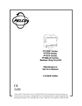
1
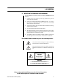
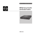
®
PT550P Series
Medium Duty
Pan/Tilt
Installation/
Operation Manual
C325M-C (6/99)
Pelco • 3500 Pelco Way, Clovis • CA 93612-5699 USA • www.pelco.com
In North America and Canada: Tel (800) 289-9100 or FAX (800) 289-9150
International Customers: Tel (1-559) 292-1981 or FAX (1-559) 348-1120
CONTENTS
Section
Page
1.0 GENERAL .................................................................................................. 3
1.1 IMPORTANT SAFEGUARDS AND WARNINGS ............................... 3
2.0 DESCRIPTION .......................................................................................... 4
2.1 MODELS ............................................................................................ 4
2.2 OPTIONS ........................................................................................... 4
2.3 RATINGS ........................................................................................... 4
3.0 INSTALLATION .......................................................................................... 5
3.1 MOUNTING ....................................................................................... 5
3.2 CAMERA/ENCLOSURE MOUNTING ............................................... 5
3.3 WIRING ............................................................................................. 5
3.3.1 Mating Connector Assembly ................................................. 7
3.4 LIMIT STOP ADJUSTMENTS ........................................................... 10
4.0 OPERATION ............................................................................................. 11
5.0 TROUBLESHOOTING .............................................................................. 12
5.1 SERVICE MANUAL .......................................................................... 12
6.0 MAINTENANCE ........................................................................................ 13
6.1 Tightening Drive Chains .................................................................... 13
6.2 Chain Drive Lubrication .................................................................... 13
7.0 SPECIFICATIONS .................................................................................... 14
8.0 WARRANTY AND RETURN INFORMATION ........................................... 16
LIST OF ILLUSTRATIONS
Figure
Page
1
2
3
4
5
6
7
Sealant Locations .............................................................................. 5
Connector Assembly .......................................................................... 7
PT550P Wiring Diagram .................................................................... 8
PT550P/PP Wiring Diagram .............................................................. 9
Limit Stops ........................................................................................ 10
Servicing the Pan/Tilt ........................................................................ 13
PT550P Series Dimension Drawing .................................................. 15
LIST OF TABLES
Table
A
Page
Maximum Cable Distances ................................................................ 6
REVISION HISTORY
2
Manual #
Date
Comments
C325M-C
10/98
Changed manual to new format. Added ratings. Revised
installation instructions. Moved exploded assembly diagram, parts lists, and potentiometer adjustment to maintenance/service manual. Reversed wire colors for pins 5
and 8 in wiring schematics.
6/99
Revised Figures 3 & 4 to include wiring for HB option.
Pelco Manual C325M-C (6/99)
1.0 GENERAL
1.1 IMPORTANT SAFEGUARDS AND WARNINGS
Prior to installation and use of this product, the following WARNINGS should be
observed.
1.
Installation and servicing should only be done by qualified service personnel
and conform to all local codes.
2.
Unless the unit is specifically marked as a NEMA Type 3, 3R, 3S, 4, 4X, 6, or
6P enclosure, it is designed for indoor use only and it must not be installed
where exposed to rain and moisture.
3.
The weight of the camera, lens, and enclosure shall not exceed 40 lb (18.16 kg),
subject to specific pan/tilt unit.
4.
Only use replacement parts recommended by Pelco.
5.
After replacement/repair of this unit’s electrical components, conduct a resistance measurement between line and exposed parts to verify the exposed
parts have not been connected to line circuitry.
6.
The installation method and materials should be capable of supporting four
times the weight of the enclosure, pan/tilt, camera and lens combination.
The product and/or manual may bear the following marks:
This symbol indicates that dangerous voltage constituting a
risk of electric shock is present within this unit.
This symbol indicates that there are important operating and
maintenance instructions in the literature accompanying this
unit.
CAUTION:
RISK OF
ELECTRIC SHOCK.
DO NOT OPEN.
CAUTION:
TO REDUCE THE RISK OF ELECTRICAL SHOCK,
DO NOT REMOVE COVER. NO USERSERVICEABLE PARTS INSIDE. REFER SERVICING
TO QUALIFIED SERVICE PERSONNEL.
Please thoroughly familiarize yourself with the information
in this manual prior to installation and operation.
Pelco Manual C325M-C (6/99)
3
2.0 DESCRIPTION
Pan/tilts in the PT550P Series are designed to remotely position a TV camera in
both the horizontal and vertical attitudes. Pan (horizontal) and tilt (vertical) movements are caused by activating small DC motors in the pan/tilt unit. All Pelco units
are equipped with adjustable limits for both pan and tilt, and all motors are equipped
with electrical filtering circuits to suppress RF interference.
The drive motors employ a permanent magnet type of field. The voltages applied
to the armature can be varied in magnitude to change motor speed and are reversed in polarity to change the direction of movement.
Braking is accomplished by electrically short-circuiting the motor armature. During
normal operation, dynamic braking is accomplished in the control unit by shortcircuiting both sides of the armature to the supply common. When a pre-adjusted
limit is encountered during operation, limit switches remove the driving voltage and
apply a short circuit to the motor armature.
2.1 MODELS
PT550P
Medium duty pan/tilt, 115 VDC
PT550P/FGP
Medium duty pan/tilt, 115 VDC, with special speed gearing for
pan (9°/sec pan speed)
PT550P/HB
Medium duty pan/tilt, 115 VDC, with blanket heater in cover. 75
watts total. 120 VAC.
PT550P/PP
Medium duty pan/tilt, 115VDC, with position feedback modification. Requires preset control or control having AZL option
(position indication meter).
PT550P/RAD
Medium duty pan/tilt, 115 VDC, with radiation resistant wiring
and white epozy paint. Low level radiation resistant up to 106
rads
2.2 OPTIONS
FG/570
Special high speed gears — 9°/4.5° per sec pan/tilt speed.
(Reduces load to 20 lb or 9.08 kg)
FGT/570
Special high-speed gearing for tilt — 4.5°/sec tilt speed.
(Reduces load to 20 lb or 9.08 kg)
2.3 RATINGS
•
•
4
NEMA Type 3R
IP 32
Pelco Manual C325M-C (6/99)
3.0 INSTALLATION
CAUTION: Pan/tilts in
the PT550P Series are
designed for upright or inver ted operation and
should never be mounted
horizontally.
Pan/tilts in the PT550P Series are designed to mount onto a horizontal surface in
the upright or inverted position.
In order to ensure proper wiring and system operation of all components, it is recommended that you test the pan/tilt and the associated control equipment in your
facility before field installation. Refer to Sections 3.3 through 3.4.
3.1 MOUNTING
NOTE: When mounting the pan/
tilt outdoors in the inverted position
(base up), RTV silicone sealant,
such as Dow Corning Type 732 or
equivalent, should be applied to the
areas indicated in Figure 1.
Attach the pan/tilt unit to a mount, following the instructions that accompany the
mount. To ensure maximum pan travel, mount the pan/tilt so that the fixed limit stop
is directly opposite the center of the intended viewing area.
Make sure the mounting surface and the mounting method is strong enough to support four times the combined weight of the pan/tilt, enclosure, camera and lens.
3.2 CAMERA/ENCLOSURE MOUNTING
Attach the enclosure, camera and lens to the pan/tilt unit with 1/4-20 hardware (not
supplied). The enclosure, camera and lens must be correctly mounted and balanced
on the tilt table for proper operation.
3.3 WIRING
Cable distances for pan and tilt motors should not exceed the distances specified in Table A. Cable fabrication must be in accordance with Section 3.3.1, Mating Connector Assembly. The following are some recommended common installation practices.
1.
Always use jacketed stranded multi-conductor interconnecting cable between
the control and the pan/tilt unit, with additional conductors than needed for
future servicing and or additions.
2.
Always use color-coded conductors for ease of wiring and to identify functions
at a later date.
3.
Keep a wiring diagram with the system for later use and reference.
➛
➛
➛
Figure 1 . Sealant Locations
Pelco Manual C325M-C (6/99)
5
Table A . Maximum Cable Distances
Wire Size
20 AWG
18 AWG
16 AWG
Maximum Distance
635 feet (193.55 m)
1,015 feet (309.37 m)
1,610 feet (490.73 m)
Distances are calculated with both motors (pan/tilt) running and assuming a 10%
voltage drop in cable.
6
Pelco Manual C325M-C (6/99)
3.3.1 Mating Connector Assembly
NOTE: Contacts cannot be removed from the connector without
the use of the appropriate AMP extraction tool (ZT305183), which is
available from Pelco.
NOTE: When a pan/tilt is mounted
in the inverted position, the LEFT/
RIGHT and UP/DOWN functions
are reversed during operation. To
correct this problem, reverse the
LEFT/RIGHT functions in the control cable (pins 3 and 7) at the pan/
tilt or control and the UP/DOWN
functions (pins 5 and 6) at the pan/
tilt or control.
To assemble the mating connectors, refer to Figure 2 and perform the following steps.
The instructions that follow apply to all AMP style connectors regardless of pin size
or pin number.
1.
Slide the connector clamp assembly over the conductor cable. If the diameter
of the conductor cable is such that the rubber boot will slide over it easily, slide
the rubber boot onto the conductor cable at this time. If not, discard the rubber
boot.
2.
Refer to Detail A in Figure 2. Prepare the wires from the conductor cable as
follows:
a.
Strip at least 1-inch (2.54 cm) from the cable jacket to expose the wires.
You may need to strip more from the cable jacket if you have more wires.
b.
Strip 1/8-inch (0.125 cm) from each wire.
c.
Using an AMP style crimper, crimp the wires and their insulation to the
connector pins.
3.
Slide the connector pins into the appropriate holes in the connector body until
they snap into place. Refer to detail B in Figure 2 and to Figure 3 or 4 for
correct pin arrangement, depending on model and options.
4.
Push the connector clamp assembly (with boot, if used) toward the connector
body. Screw the clamp assembly onto the connector body, being careful not to
disturb the wires.
5.
To complete the assembly, attach the appropriate clamp with the screws provided and tighten.
1"
1/8"
FRONT VIEW
OR
3
1
6
4
9
2
1
6
3
10
14
7
7
11
16 15
00005
9-PIN
16-PIN
Figure 2. Connector Assembly
Pelco Manual C325M-C (6/99)
7
Figure 3. PT550P Wiring Diagram (including HB Option)
8
Pelco Manual C325M-C (6/99)
Figure 4. PT550P/PP Wiring Diagram (including HB Option)
Pelco Manual C325M-C (6/99)
9
3.4 LIMIT STOP ADJUSTMENTS
WARNING: Do not
operate the pan/tilt
without limit stops.
Do not attempt to adjust
the limit stops while the
unit is operating. Personal injury or damage
to the unit may result.
Do not remove or reposition the
fixed limit stop on the pan/tilt.
DAMAGE WILL OCCUR.
To set pan/tilt limit stops, perform the following steps. Refer to Figure 5.
1.
Loosen the pan limit stops.
2.
Turn the control unit on. Pan the unit to the right until the desired right pan limit
is reached.
3.
Move the right pan limit stop until it touches the pan limit switch actuator. Move
the stop a slight distance further against the actuator until it clicks to indicate
the opening of the limit switch. Lock the stop in place.
4.
Pan the unit to the desired left position. Adjust the left pan limit stop as described in step 3.
5.
Pan left and right to both limit stops and check for exact positioning. Tighten
both stops securely.
6.
Remove the cover plate from the left side of the tilt table. Loosen the limit stop
screws and tilt the table, using the joystick, to the desired up position.
7.
Move the up limit stop until it touches the tilt limit switch actuator and clicks.
Lock the stop in place.
8.
Tilt the table to the desired down position and set the stop in the same manner.
9.
Tilt the table up and down and check for exact positioning. Tighten both stops
securely. Replace the cover plate.
Figure 5. Limit Stops
10
Pelco Manual C325M-C (6/99)
4.0 OPERATION
Refer to the manual for your control equipment for operating the pan/tilt.
Pelco Manual C325M-C (6/99)
11
5.0 TROUBLESHOOTING
Some common problems encountered with pan/tilt systems include miswiring, overloading, and not using the units for the correct application. If the pan/tilt unit fails to
operate, do the following:
1.
Check the fuse in the control unit. If the fuse is bad, replace it.
2.
If the fuse blows after replacing it, check the control cable between the control
unit and the pan/tilt for shorts, high resistance, or opens.
3.
If the control cable is good, reconnect it to the control unit but not to the pan/
tilt. Replace the fuse and operate the control unit. If the fuse blows again, the
fault is in the control.
Refer to Figure 3 or 4 for the following steps.
4.
If the control unit is good, check the wiring harness in the pan/tilt for shorts.
5.
If the wiring harness is good, the problem is internal to the unit; consult the
factory.
5.1 SERVICE MANUAL
If you need to service your unit, obtain a service manual in one of the following
ways:
12
•
Go to Pelco’s web site at http://www.pelco.com and find service manual
C325SM.
•
Contact Pelco’s Literature Department and request service manual C325SM.
Pelco Manual C325M-C (6/99)
6.0 MAINTENANCE
Inspect the pan/tilt unit every six months to ensure trouble-free operation and an
extended product life. Harsh environments and/or continuous motion applications
may require more frequent maintenance.
Please read all of the instructions that follow before servicing the pan/tilt.
To begin, remove the three screws on the front of the pan/tilt housing and lift the
cover to gain access to the pan and tilt motor assemblies.
6.1 TIGHTENING DRIVE CHAINS
Check the pan and tilt drive chains for tension. A movement of 1/32 of an inch to 3/32
of an inch in the chains is acceptable. If the movement of a chain exceeds 3/32 of an
inch, adjust the chain as follows:
1.
Loosen the screws securing the motor to the mounting frame.
2.
Pry on the motor to apply tension to the chain. Do not over-tension the drive
chain.
3.
Keep tension on the chain while tightening the screws.
6.2 CHAIN DRIVE LUBRICATION
Sprockets, chains, and gears should be well greased. If necessary, lubricate the
pan and tilt gears, sprockets, and chains as follows with a high-quality grease capable of withstanding temperatures from -50° to 170°F (-46° to 77°C). Do the following:
1.
Liberally apply grease to the pan and tilt gears, chains, and sprockets (refer to
Figure 6).
2.
Operate the pan and tilt motors to spread the grease across the parts.
3.
Apply additional grease if necessary.
4.
Reinstall the cover. If the pan/tilt is installed outdoors in an inverted position,
apply RTV silicone sealant as shown in Figure 1.
Figure 6. Servicing the Pan/Tilt
Pelco Manual C325M-C (6/99)
13
7.0 SPECIFICATIONS
MECHANICAL
Pan:
0-355° movement in horizontal plane
Speed
6°/sec ±1° (No load condition)
Tilt:
±90° movement in vertical plane
Speed
3°/sec ± .5° (No load condition)
Torque 20 ft/lb with specified voltage
Maximum Load:
40 lb (18.16 kg) at 5 inches (12.7 cm) from tilt table surface to
center of gravity
Gearing:
Adjustable worm-gear final drive to prevent drift and minimize
backlash
Bearings
Pan:
Tilt:
Heavy-duty ball bearings
Oilite bronze bushing
Braking:
Dynamic for instantaneous stopping
ELECTRICAL
Input Voltage:
115 VDC required for pan/tilt
Power Requirements
Running:
Pan:
.30 amp (34 vA)
Tilt:
.30 amp (34 vA)
Pan:
Tilt:
Connectors:
AMP CPC type (mate supplied)
Motors:
115 VDC permanent magnet
Limit Switches
Pan:
Tilt:
Interference:
Conductor
Requirements:
14
Starting:
.44 amp (51 vA)
.44 amp (51 vA)
5 amp
5 amp
External adjustment
Electrical filtering to minimize starting and stopping glitches
6, unshielded (Functions: left, right, up, down, motor common,
safety ground)
(Variable speed, no additional conductors. For models with PP
option, an additional 4 conductors are required.)
Pelco Manual C325M-C (6/99)
GENERAL
Construction:
Aluminum plate; all internal parts corrosion protected
Environment:
Indoor/outdoor; completely weatherproofed
Temperature:
-10°F to 120°F (-23°C to 49°C)
Dimensions:
See Figure 7
Weight:
22 lb (9.9 kg)
Shipping Weight:
PT550P/PP
All others
25 lb (11.5 kg)
24 lb (10.87 kg)
(Design and product specifications subject to change without notice.)
Figure 7. PT550P Series Dimension Drawing
Pelco Manual C325M-C (6/99)
15
8.0 WARRANTY AND RETURN INFORMATION
WARRANTY
Pelco will repair or replace, without charge, any merchandise proved defective in material or workmanship for a period of one year after the date of shipment.
Exceptions to this warranty are as noted below:
• Five years on FT/FR8000 Series fiber optic products.
• Three years on Genex® Series products (multiplexers, server, and keyboard).
• Three years on Camclosure® and fixed camera models, except the CC3701H-2, CC3701H-2X,
CC3751H-2, CC3651H-2X, MC3651H-2, and CC3651H-2X camera models, which have a five-year
warranty.
• Two years on standard motorized or fixed focal length lenses.
• Two years on Legacy®, CM6700/CM6800/CM9700 Series matrix, and DF5/DF8 Series
fixed dome products.
• Two years on Spectra®, Esprit®, ExSite™, and PS20 Scanners, including when used in continuous
motion applications.
• Two years on Esprit® and WW5700 Series window wiper (excluding wiper blades).
• Eighteen months on DX Series digital video recorders, NVR300 Series network video recorders, and
Endura™ Series distributed network-based video products.months on DX Series digital video
recorders, NVR300 Series network video recorders, Endura™ Series distributed network-based video
products, and TW3000 Series twisted pair transmission products.
• One year (except video heads) on video cassette recorders (VCRs). Video heads will be covered for a
period of six months.
• Six months on all pan and tilts, scanners or preset lenses used in continuous motion applications
(that is, preset scan, tour and auto scan modes).
Pelco will warrant all replacement parts and repairs for 90 days from the date of Pelco shipment. All
goods requiring warranty repair shall be sent freight prepaid to Pelco, Clovis, California. Repairs made
necessary by reason of misuse, alteration, normal wear, or accident are not covered under this
warranty.
Pelco assumes no risk and shall be subject to no liability for damages or loss resulting from the
specific use or application made of the Products. Pelco’s liability for any claim, whether based on
breach of contract, negligence, infringement of any rights of any party or product liability, relating to the
Products shall not exceed the price paid by the Dealer to Pelco for such Products. In no event will
Pelco be liable for any special, incidental or consequential damages (including loss of use, loss of
profit and claims of third parties) however caused, whether by the negligence of Pelco or otherwise.
The above warranty provides the Dealer with specific legal rights. The Dealer may also have additional
rights, which are subject to variation from state to state.
If a warranty repair is required, the Dealer must contact Pelco at (800) 289-9100 or (559) 292-1981 to
obtain a Repair Authorization number (RA), and provide the following information:
1. Model and serial number
2. Date of shipment, P.O. number, Sales Order number, or Pelco invoice number
3. Details of the defect or problem
If there is a dispute regarding the warranty of a product which does not fall under the warranty
conditions stated above, please include a written explanation with the product when returned.
Method of return shipment shall be the same or equal to the method by which the item was received by
Pelco.
RETURNS
In order to expedite parts returned to the factory for repair or credit, please call the factory at (800)
289-9100 or (559) 292-1981 to obtain an authorization number (CA number if returned for credit, and
RA number if returned for repair).
All merchandise returned for credit may be subject to a 20% restocking and refurbishing charge.
Goods returned for repair or credit should be clearly identified with the assigned CA or RA number and
freight should be prepaid. Ship to the appropriate address below.
If you are located within the continental U.S., Alaska, Hawaii or Puerto Rico, send goods to:
Service Department
Pelco
3500 Pelco Way
Clovis, CA 93612-5699
If you are located outside the continental U.S., Alaska, Hawaii or Puerto Rico and are instructed to
return goods to the USA, you may do one of the following:
If the goods are to be sent by a COURIER SERVICE, send the goods to:
Pelco
3500 Pelco Way
Clovis, CA 93612-5699 USA
If the goods are to be sent by a FREIGHT FORWARDER, send the goods to:
Pelco c/o Expeditors
473 Eccles Avenue
South San Francisco, CA 94080 USA
Phone: 650-737-1700
Fax: 650-737-0933
® Pelco, the Pelco logo, Spectra, Esprit, Genex, Legacy, and Camclosure are registered trademarks of Pelco.
™ Endura and ExSite are trademarks of Pelco.
© Copyright 1997, Pelco. All rights reserved.
16
Pelco Manual C325M-C (6/99)