1
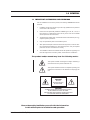
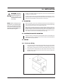
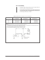
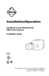
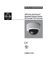
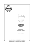
®
PT680-24 Series
Pan/Tilts
Installation/
Operation Manual
C337M-E (7/03)
Pelco World Headquarters • 3500 Pelco Way, Clovis, CA 93612-5699 USA • www.pelco.com
USA & Canada: Tel: 800/289-9100 • Fax: 800/289-9150
International: Tel: 1-559/292-1981 • Fax: 1-559/348-1120
CONTENTS
Section
Page
1.0 GENERAL ................................................................................................... 3
1.1 IMPORTANT SAFEGUARDS AND WARNINGS ............................... 3
2.0 DESCRIPTION .......................................................................................... 4
2.1 MODELS ............................................................................................ 4
2.2 OPTIONS ........................................................................................... 4
2.3 CERTIFICATIONS ............................................................................. 4
3.0 INSTALLATION .......................................................................................... 5
3.1 MOUNTING ....................................................................................... 5
3.2 CAMERA/ENCLOSURE MOUNTING ............................................... 5
3.3 WIRING ............................................................................................. 5
3.3.1 Enclosure Wiring ..................................................................... 5
3.3.2 Control Wiring ......................................................................... 6
3.4 LIMIT STOP ADJUSTMENTS ............................................................ 13
4.0 OPERATION ............................................................................................. 14
5.0 TROUBLESHOOTING .............................................................................. 15
5.1 SERVICE MANUAL .......................................................................... 15
6.0 MAINTENANCE ........................................................................................ 16
6.1 TIGHTENING DRIVE CHAINS ......................................................... 16
6.2 CHAIN DRIVE LUBRICATION .......................................................... 16
7.0 SPECIFICATIONS .................................................................................... 17
8.0 WARRANTY AND RETURN INFORMATION ........................................... 20
LIST OF ILLUSTRATIONS
Figure
1
2
3
4
5
6
7
8
9
10
Page
Sealant Locations .............................................................................. 5
PT680-24P Wiring Schematic ............................................................ 7
PT680-24SL Wiring Schematic .......................................................... 8
PT680-24P/PP Wiring Schematic ...................................................... 9
PT680-24SL/PP Wiring Schematic ................................................... 10
PT680-24P/HB Wiring Schematic ..................................................... 11
PT680-24SL/HB Wiring Schematic ................................................... 12
Limit Stops ........................................................................................ 13
Servicing the Pan/Tilt ........................................................................ 16
PT680-24 Series Dimension Drawing ............................................... 18
LIST OF TABLES
Table
A
2
Page
Requirements to Wire Power to Pan and Tilt Motors ......................... 6
Pelco Manual C337M-E (7/03)
1.0 GENERAL
1.1 IMPORTANT SAFEGUARDS AND WARNINGS
Prior to installation and use of this product, the following WARNINGS should be
observed.
1.
Installation and servicing should only be done by qualified service personnel
and conform to all local codes.
2.
Unless the unit is specifically marked as a NEMA Type 3, 3R, 3S, 4, 4X, 6, or
6P enclosure, it is designed for indoor use only and it must not be installed
where exposed to rain and moisture.
3.
The weight of the camera, lens, and enclosure shall not exceed 50 lb (22.7 kg),
subject to specific pan/tilt unit.
4.
Only use replacement parts recommended by Pelco.
5.
After replacement/repair of this unit’s electrical components, conduct a resistance measurement between line and exposed parts to verify the exposed
parts have not been connected to line circuitry.
6.
The installation method and materials should be capable of supporting four
times the weight of the enclosure, pan/tilt, camera and lens combination.
The product and/or manual may bear the following marks:
This symbol indicates that dangerous voltage constituting a
risk of electric shock is present within this unit.
This symbol indicates that there are important operating and
maintenance instructions in the literature accompanying this
unit.
CAUTION:
RISK OF
ELECTRIC SHOCK.
DO NOT OPEN.
CAUTION:
TO REDUCE THE RISK OF ELECTRICAL SHOCK,
DO NOT REMOVE COVER. NO USERSERVICEABLE PARTS INSIDE. REFER SERVICING
TO QUALIFIED SERVICE PERSONNEL.
Please thoroughly familiarize yourself with the information
in this manual prior to installation and operation.
Pelco Manual C337M-E (7/03)
3
2.0 DESCRIPTION
The pan/tilt units of the PT680-24 Series are designed for medium-duty, indoor/
outdoor use. The housings are made of aluminum and will hold a maximum load of
50 pounds (22.7 kg).
The units include factory-wired cables to connect the pan/tilt to the camera enclosure and to the control unit. The pan/tilts also feature rugged worm-gear final drive
assemblies to minimize backlash and prevent wind drift, and are fully adjustable for
wear.
2.1 MODELS
PT680-24P
Medium-duty, indoor/outdoor, 24 VAC.
PT680-24P/PP
PT680-24P with preset positioning capabilities.
PT680-24SL
PT680-24P with 360° pan rotation.
PT680-24SL/PP
PT680-24SL with preset positioning capabilities.
2.2 OPTIONS
HB/680
Spot/blanket heater. Allows operation to -50°F (-46°C). 75 watts.
120 VAC, 50/60 Hz.
2.3 CERTIFICATIONS
The products identified below have been tested and certified for agency compliance as noted.
Agency Compliance Certification
Model
PT680-24P
CE
FCC
UL
X
PT680-24P/PP
X
PT680-24SL
X
PT680-24SL/PP
X
CSA/cUL
Applicable CE, FCC, UL, and CSA/cUL standards:
•
•
CE Class B
UL Standard 2044
Additional applicable ratings:
•
•
4
NEMA Type 3R
IP 32
Pelco Manual C337M-E (7/03)
3.0 INSTALLATION
CAUTION: Pan/tilts in
the PT680-24 Series are
designed for upright or inverted operation and
should never be mounted
horizontally.
Pan/tilts in the PT680-24 Series are designed to mount onto a horizontal surface in
the upright or inverted position.
In order to ensure proper wiring and system operation of all components, it is recommended that you test the pan/tilt and the associated control equipment in your
facility before field installation. Refer to Sections 3.3 through 3.4.
3.1 MOUNTING
NOTE: When mounting the pan/
tilt outdoors in the inverted position
(base up), RTV silicone sealant,
such as Dow Corning Type 732 or
equivalent, should be applied to the
areas indicated in Figure 1.
Attach the pan/tilt unit to a mount, following the instructions that accompany the
mount. To ensure maximum pan travel, mount the pan/tilt so that the fixed limit stop
is directly opposite the center of the intended viewing area.
Make sure the mounting surface and the mounting method is strong enough to support four times the combined weight of the pan/tilt, enclosure, camera and lens. The
pan/tilt unit weighs 21 pounds 3 ounces (9.53 kg). Refer to the manuals for your
enclosure, camera, and lens for the weights of those units. The weight of the enclosure, camera, and lens must not exceed 50 pounds (22.7 kg).
3.2 CAMERA/ENCLOSURE MOUNTING
Attach the enclosure, camera and lens to the pan/tilt unit with 1/4-20 hardware (not
supplied). The enclosure, camera and lens must be correctly mounted and balanced
on the tilt table for proper operation.
3.3 WIRING
3.3.1 Enclosure Wiring
1.
Connect the gray cable from the side of the pan/tilt unit to the enclosure. Refer
to Figures 2 through 7 for wire designations. Leave adequate slack in the
cable to permit movement of the enclosure without putting strain on the cable.
2.
Connect the black coaxial cable to the video output of the camera. Leave
adequate slack in the cable to permit movement of the enclosure without putting strain on the cable.
➛
➛
➛
Figure 1. Sealant Locations
Pelco Manual C337M-E (7/03)
5
3.3.2 Control Wiring
1.
A cable with a 16-pin or 28-pin connector on one end is supplied. Fasten the
connector to its mate in the base of the pan/tilt unit.
2.
Connect the other end of the cable to the control unit. Refer to Figures 2 through
7 for wire designations. Refer to Table A for the maximum cable distances for
wiring power to the pan/tilt unit. If an RB24 Relay Box is not used, the maximum cable length is distance “B” in the table.
Table A. Requirements to Wire Power to Pan and Tilt Motors
Wire Size (AWG)
20
18
16
Maximum Distance “A”
(5 Conductors)
Maximum Distance “B”
(5 Conductors*)
5,800 ft (1,768 m)***
8,250 ft (2,804 m)
13,000 ft (4,420 m)
60 ft (18.29 m)
95 ft (28.96 m)
155 ft (47.24 m)
Maximum Distance “B”
(6 Conductors**)
115 ft (35.05 m)
185 ft (56.39 m)
295 ft (89.92 m)
NOTE: If RB24 Relay Box is not used, maximum cable length is distance “B.”
* Conductors are for up, down, left, and right functions, plus motor common. Cable distances are calculated with both motors
(pan and tilt) running and assuming a 10% voltage drop in the cable.
** Same as five conductors except two wires are used for motor common.
*** Not recommended for reliable service between control and relay box.
A
CONTROL
B
RB24
REQUIRES EXTERNAL
POWER SUPPLY
6
Pelco Manual C337M-E (7/03)
1
3
4
7
2
6
5
8
9 10
11 12 13 14
15 16
Figure 2. PT680-24P Wiring Schematic
Pelco Manual C337M-E (7/03)
7
1
3
4
7
2
6
5
8
9 10
11 12 13 14
15 16
Figure 3. PT680-24SL Wiring Schematic
8
Pelco Manual C337M-E (7/03)
Figure 4. PT680-24P/PP Wiring Schematic
Pelco Manual C337M-E (7/03)
9
Figure 5. PT680-24SL/PP Wiring Schematic
10
Pelco Manual C337M-E (7/03)
Figure 6. PT680-24P/HB Wiring Schematic
Pelco Manual C337M-E (7/03)
11
Figure 7. PT680-24SL/HB Wiring Schematic
12
Pelco Manual C337M-E (7/03)
3.4 LIMIT STOP ADJUSTMENTS
WARNING: Do not
operate the pan/tilt
without limit stops.
Do not attempt to adjust
the limit stops while the
unit is operating. Personal injury or damage
to the unit may result.
To set pan/tilt limit stops, perform the following steps. Refer to Figure 8.
1.
Loosen the pan limit stops.
2.
Turn the control unit on. Pan the unit to the right until the desired right pan limit
is reached.
3.
Move the right pan limit stop until it touches the pan limit switch actuator. Move
the stop a slight distance further against the actuator until it clicks to indicate
the opening of the limit switch. Lock the stop in place.
4.
Pan the unit to the desired left position. Adjust the left pan limit stop as described in step 3.
5.
Pan left and right to both limit stops and check for exact positioning. Tighten
both stops securely.
6.
Remove the cover plate from the left side of the tilt table. Turn on the control
unit if you are starting at this step. Loosen the limit stop screws and tilt the
table, using the joystick, to the desired up position.
7.
Move the up limit stop until it touches the tilt limit switch actuator and clicks.
Lock the stop in place.
8.
Tilt the table to the desired down position and set the stop in the same manner.
9.
Tilt the table up and down and check for exact positioning. Tighten both stops
securely. Replace the cover plate.
Do not remove or reposition the
fixed limit stop on the pan/tilt.
DAMAGE WILL OCCUR.
NOTE : The PT680-24SL and
PT680-24SL/PP do not have pan
limit stops. Disregard steps 1-5.
Figure 8. Limit Stops
Pelco Manual C337M-E (7/03)
13
4.0 OPERATION
Refer to the manual for your control equipment for operating the pan/tilt.
14
Pelco Manual C337M-E (7/03)
5.0 TROUBLESHOOTING
Some common problems encountered with pan/tilt systems include miswiring, overloading, and not using the units for the correct application. If the pan/tilt unit fails to
operate, do the following:
1.
Check the fuse in the control unit. If the fuse is bad, replace it.
2.
If the fuse blows after replacing it, check the control cable between the control
unit and the pan/tilt for shorts, high resistance, or opens.
3.
If the control cable is good, reconnect it to the control unit but not to the pan/
tilt. Replace the fuse and operate the control unit. If the fuse blows again, the
fault is in the control.
Refer to Figures 2-7 for the following steps.
4.
If the control unit is good, check the wiring harness in the pan/tilt for shorts.
5.
If the wiring harness is good, check the motor starting capacitors.
6.
If the starting capacitors are good, check the motors for opens and shorts.
There should be low resistance between the windings.
7.
Check the limit switches for opens and shorts.
5.1 SERVICE MANUAL
If you need to service your unit, obtain a service manual in one of the following
ways:
Pelco Manual C337M-E (7/03)
•
Go to Pelco’s web site at http://www.pelco.com and find service manual
C325SM.
•
Call Pelco’s DataFAX service at 1-559-292-0435 and request document
23258.
•
Contact Pelco’s Literature Department and request service manual C325SM.
15
6.0 MAINTENANCE
Inspect the pan/tilt unit every six months to ensure trouble-free operation and an
extended product life. Harsh environments and/or continuous motion applications
may require more frequent maintenance.
Please read all of the instructions that follow before servicing the pan/tilt.
To begin, remove the three screws on the front of the pan/tilt housing and lift the
cover to gain access to the pan and tilt motor assemblies.
6.1 TIGHTENING DRIVE CHAINS
Check the pan and tilt drive chains for tension. A movement of 1/32 of an inch to 3/32
of an inch in the chains is acceptable. If the movement of a chain exceeds 3/32 of an
inch, adjust the chain as follows:
1.
Loosen the screws securing the motor to the mounting frame.
2.
Pry on the motor to apply tension to the chain. Do not over-tension the drive
chain.
3.
Keep tension on the chain while tightening the screws.
6.2 CHAIN DRIVE LUBRICATION
Sprockets, chains, and gears should be well greased. If necessary, lubricate the
pan and tilt gears, sprockets, and chains as follows with a high-quality grease capable of withstanding temperatures from -50° to 170°F (-46° to 77°C). Do the following:
1.
Liberally apply grease to the pan and tilt gears, chains, and sprockets (refer to
Figure 9).
2.
Operate the pan and tilt motors to spread the grease across the parts.
3.
Apply additional grease if necessary.
4.
Reinstall the cover. If the pan/tilt is installed outdoors in an inverted position,
apply RTV silicone sealant as shown in Figure 1.
Figure 9. Servicing the Pan/Tilt
16
Pelco Manual C337M-E (7/03)
7.0 SPECIFICATIONS
MECHANICAL
Pan
Horizontal
Movement:
Speed:
Torque:
Tilt
Vertical
Movement:
Speed:
0-355° (Models PT680-24P and PT680-24P/PP)
360° (Models PT680-24SL and PT680-24SL/PP)
9°/sec ±1° (no load condition)
10 ft lb with specified voltage
±90°
3°/sec ±.5° (no load condition)
Maximum Load:
50 lb (22.7 kg) at 5 inches (12.7 cm) from tilt table surface to
center of gravity
Gearing:
Adjustable worm gear final drive
Bearings:
Heavy duty ball bearings (pan)
Oilite bronze bushing (tilt)
Duty Cycle:
50% duty cycle; 30-minute rating
ELECTRICAL
Input Voltage:
24 VAC, 50/60 Hz, required for pan/tilt
Power
Requirements:
Pan
Tilt
.9 amp (21.6 vA)
1.0 amp (24.0 vA)
Maximum
Current:
2 amps per conductor (SL models only)
Connectors:
Amp CPC type, mate supplied
Motors:
Two-phase induction type, continuous duty, instantaneous
reversing
Limit Switches:
Pan and tilt - 5 amp, 10 million cycle rating (external adjustment)
Conductor
Requirements:
PT680-24P and
PT680-24SL
13 plus ground and coax
PT680-24P/PP 18 plus ground and coax
PT680-24SL/PP 19 plus ground and coax
GENERAL
Pelco Manual C337M-E (7/03)
Construction:
Dimensions:
Aluminum plate, all parts corrosion protected
See Figure 10
Environment:
Indoor/outdoor
Temperature:
-10° to 120°F (-23° to 49°C)
Weight
Unit:
Shipping:
All models - 21.19 lb (9.53 kg)
All models - 26 lb (11.77 kg)
17
Figure 10. PT680-24 Series Dimension Drawing
18
Pelco Manual C337M-E (7/03)
NOTES
Pelco Manual C337M-E (7/03)
19
8.0 WARRANTY AND RETURN INFORMATION
WARRANTY
Pelco will repair or replace, without charge, any merchandise proved defective in
material or workmanship for a period of one year after the date of shipment. Exceptions to this warranty are as noted below:
•
•
•
•
•
•
•
•
•
•
Five years on Pelco manufactured cameras (CC3500/CC3600/CC3700 and
MC3500/MC3600 Series); two years on all other cameras.
Three years on Genex® Series (multiplexers, server, and keyboard) and
090 Series Camclosure® Camera System.
Two years on 100/150, 200, and 300 Series Camclosure Camera Systems.
Two years on all standard motorized or fixed focal length lenses.
Two years on Legacy ® , CM6700/CM6800/CM6800E/CM8500/CM9500/
CM9740/CM9760 Matrix, DF5 and DF8 Series Fixed Dome products.
Two years on Spectra®, Esprit®, and PS20 Scanners, including when used in
continuous motion applications.
Two years on Esprit and WW5700 series window wiper (excluding wiper blades).
Eighteen months on DX Series digital video recorders.
One year (except video heads) on video cassette recorders (VCRs). Video heads
will be covered for a period of six months.
Six months on all pan and tilts, scanners or preset lenses used in continuous
motion applications (that is, preset scan, tour and auto scan modes).
Pelco will warrant all replacement parts and repairs for 90 days from the date of
Pelco shipment. All goods requiring warranty repair shall be sent freight prepaid
to Pelco, Clovis, California. Repairs made necessary by reason of misuse,
alteration, normal wear, or accident are not covered under this warranty.
Pelco assumes no risk and shall be subject to no liability for damages or loss
resulting from the specific use or application made of the Products. Pelco’s liability
for any claim, whether based on breach of contract, negligence, infringement of
any rights of any party or product liability, relating to the Products shall not exceed
the price paid by the Dealer to Pelco for such Products. In no event will Pelco be
liable for any special, incidental or consequential damages (including loss of use,
loss of profit and claims of third parties) however caused, whether by the negligence
of Pelco or otherwise.
The above warranty provides the Dealer with specific legal rights. The Dealer may
also have additional rights, which are subject to variation from state to state.
If a warranty repair is required, the Dealer must contact Pelco at (800) 289-9100
or (559) 292-1981 to obtain a Repair Authorization number (RA), and provide the
following information:
1. Model and serial number
2. Date of shipment, P.O. number, Sales Order number, or Pelco invoice number
3. Details of the defect or problem
If there is a dispute regarding the warranty of a product which does not fall under
the warranty conditions stated above, please include a written explanation with
the product when returned.
Method of return shipment shall be the same or equal to the method by which the
item was received by Pelco.
RETURNS
In order to expedite parts returned to the factory for repair or credit, please call
the factory at (800) 289-9100 or (559) 292-1981 to obtain an authorization number (CA number if returned for credit, and RA number if returned for repair).
All merchandise returned for credit may be subject to a 20% restocking and
refurbishing charge.
Goods returned for repair or credit should be clearly identified with the assigned
CA or RA number and freight should be prepaid. Ship to the appropriate address
below.
If you are located within the continental U.S., Alaska, Hawaii or Puerto Rico:
Service Department
Pelco
3500 Pelco Way
Clovis, CA 93612-5699
If you are located outside the continental U.S., Alaska, Hawaii or Puerto Rico:
Intermediate Consignee
American Overseas Air Freight
320 Beach Road
Burlingame, CA 94010
USA
Ultimate Consignee
Pelco
3500 Pelco Way
Clovis, CA 93612-5699
USA
REVISION HISTORY
Manual #
C337M
C337M
Date
11/89
1/90
C337M
C337M-C
1/91
9/96
C337M-D
10/98
C337M-E
7/03
Comments
Original version.
Rev. A. Added additional options in Section 2.2. Revised Section 4.4 to reflect pre-assembled connector. Incorporated addendums
with revised schematics.
Rev. B. Added Sections 1.1, 7.0 and 8.0. Added figure to show where to seal an inverted unit.
Revised installation instructions, updated to new manual style, and incorporated ECO #96-083 and addendums dated 9/21/92
and 7/18/96 .
Changed manual to new format. Added certifications. Revised installation instructions. Moved exploded assembly diagram, parts
lists, and potentiometer adjustment to maintenance/service manual.
Revised Figures 2 and 3 to correct front view of 16-pin connector.
® Pelco, the Pelco logo, Spectra, Genex, Legacy, Esprit and Camclosure are registered trademarks of Pelco.
20
© Copyright 2003, Pelco.
All rights reserved.
Pelco Manual C337M-E (7/03)