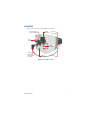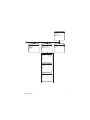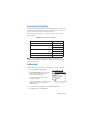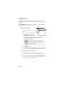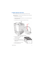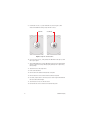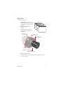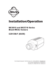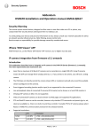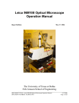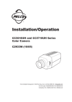
1
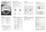
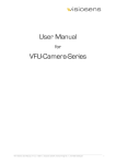
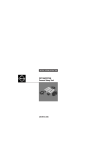
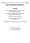
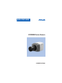
QUICK START GUIDE
CCC5100H Series Camera
C2910M-B-QS (2/06)
This quick start guide describes how to install and configure the CCC5100H Series camera in
most applications. It contains a representation of the setup menus to help you locate and
change specific settings.
BEFORE YOU BEGIN
DOCUMENTATION
Refer to the enclosed CD for the following documentation:
•
Installation/Operation manual: INSTALL.PDF
•
Quick Start Guide: QSG.PDF
Important Safety Instructions: SAFETY.PDF
•
MODELS
CCC5100H-6A 1/3-inch high resolution digital color camera, 12 VDC/24 VAC, CMY
color filter array
AUTO IRIS LENS
Before using a DC-drive auto iris lens, you must adjust the DC offset setting (refer to
DC-Drive Auto Iris Lens Setup ).
2
C2910M-B-QS (2/06)
HARDWARE
Refer to Figure 1 as you install the CCC5100H Series camera.
MULTIFUNCTION
(RJ45-10) CONNECTOR
POWER
CONNECTOR
BACK FOCUS
ADJUSTMENT
VIDEO
CONNECTOR
SETUP
BUTTONS
AUTO IRIS
LENS CABLE
AND CONNECTOR
(OPTIONAL)
SERVICE
CONNECTOR
C/CS LENS
Figure 1. CCC5100H Connectors
C2910M-B-QS (2/06)
3
LENS
The CCC5100H Series camera supports both manual and DC-drive auto iris lenses,
either fixed focal length or varifocal. The camera accepts both CS- and C-mount lenses
without an adapter.
To mount the lens onto the camera:
1. Use clean, compressed air to remove any dust or other foreign matter between
the lens and the camera imager.
2. Screw the lens onto the lens mount.
3. DC-drive auto iris lens: Connect the four-pin connector from the lens to the
connector on the back of the camera.
NOTE: Before using a DC-drive auto iris lens, you must adjust the DC offset setting
(refer to DC-Drive Auto Iris Lens Setup ).
MOUNT
The CCC5100H Series camera can be mounted from either the top or bottom. Use a
mount or enclosure that includes a standard 1/4-20 screw with a maximum thread
length of 0.375 inches (10 mm). If using the Pelco PCM150 camera mount, refer to the
PCM150 Installation manual.
4
C2910M-B-QS (2/06)
CONNECTIONS
The CCC5100H Series camera offers standard power and coax video connectors.
To use the RJ45-10 multifunction connector that combines power, video, and control
leads, refer to Multifunction Connector in the Installation/Operation manual.
LOW VOLTAGE POWER
Connect 12 VDC or 24 VAC power to the two-pin power connector on the back of the
camera. Use a Class 2 isolated power source for the CCC5100H Series camera that can
supply 12-36 VDC ±10% or 24-28 VAC ±10%, 47-63 Hz.
COAX VIDEO
Connect a video cable to the BNC connector on the back of the camera.
VIDEO FORMAT OVERRIDE
At power-up, the CCC5100H Series camera automatically selects the correct video
format. To manually override the video format selection
press and hold the top and center buttons to select NTSC, or
•
•
press and hold the center and bottom buttons to select PAL.
NOTE: If using DC power in a PAL installation without Pelco V-Sync, use the twobutton override to select PAL. Otherwise, the camera will default to NTSC.
C2910M-B-QS (2/06)
5
SETUP MENUS
Use the setup menus to customize the camera settings. Refer to the setup menus as
shown on this and the opposite page:
MAIN MENU
<LANGUAGE>
<LENS/VIDEO SIGNAL>
<CAMERA DISPLAY>
<LIGHT METER>
<WHITE BALANCE>
<PROFILES>
<SYSTEM INFORMATION>
EXIT
LANGUAGE
ENGLISH
ESPAÑOL
PORTUGUÊS
DEUTSCH
FRANÇAIS
ITALIANO
BACK
EXIT
LENS/ VIDEO SIGNAL
VIDEO STANDARD
AUTO
AUTOMATIC (AGC)
ON
LENS TYPE
DC
<LINE SYNC>
<VIDEO LEVEL>
<AUTO IRIS>
<FINE FOCUS>
BACK
EXIT
LINE SYNC
LINE SYNC
V-PHASE ADJ
INTERNAL
|------+------|
0
624
BACK
EXIT
VIDEO LEVEL
VIDEO LEVEL
|------+------|
1.0
1.2
0.0
IRE SETUP
BACK
EXIT
CAMERA DISPLAY
CAMERA NAME
CCC5100H
RX ADDRESS
1
SAVE RX ADDRESS
<DISPLAY PROPERTIES>
<GAMMA/SATURATION>
<GAIN CONTROL>
<SHARPNESS>
BACK
EXIT
DISPLAY PROPERTIES
NAME POS.
UPPER LEFT
COLOR BARS
OFF
HORIZ IMAGE FLIP
OFF
BLACK / WHITE MODE
OFF
BACK
EXIT
GAMMA /SATURATION
GAMMA CORRECTION
AUTO
MANUAL GAMMA |------+------|
25
100
SATURATION
|------+------|
-8
8
BACK
EXIT
AUTO IRIS
DC OFFSET
|------+------|
0
255
SAVE DC OFFSET
DC GAIN
BRIGHT LIM.
|------+------|
0
255
|------+------|
-34
20
BACK
EXIT
GAIN CONTROL
AUTOMATIC (AGC)
ON
BRIGHTNESS
|------+------|
-18
18
DARK LIMIT
|------+------|
0
44
MANUAL GAIN
|------+------|
-34
60
BACK
EXIT
SHARPNESS
FINE FOCUS
100
BACK
EXIT
OVERALL
APERTURE
DETAIL BOOST
BACK
EXIT
6
|------+------|
-8
8
|------+------|
-8
8
ON
C2910M-B-QS (2/06)
SYSTEM INFORMATION
FIRMWARE VER.
1.1.1
OSD VER.
1.12.0
RESTART CAMERA
RESTORE FACTORY SETTINGS
BACK
EXIT
LIGHT METER
ACTIVE ZONE
EDIT ZONE1
EDIT ZONE2
EDIT ZONE3
EDIT ZONE4
BACK
EXIT
WHITE BALANCE
ZONE 2
MODE
ATW NORMAL
<ATW NORMAL /DESAT>
<MANUAL RED/BLUE>
<MANUAL COLOR TEMP>
BACK
EXIT
PROFILES
ACTIVE
SAVE AS
DEFAULT
BACK
EXIT
WDR
CUSTOM1
WDR
ATW NORMAL /DESAT
LOW LIMIT
|------+------|
2k
5.5k
HIGH LIMIT
|------+------|
5.5k
11k
BACK
EXIT
MANUAL RED/BLUE
RED GAIN
BLUE GAIN
|------+------|
-20
20
|------+------|
-20
20
BACK
EXIT
MANUAL COLOR TEMP
COLOR TEMP
|------+------|
2.4k
11k
BACK
EXIT
C2910M-B-QS (2/06)
7
ACCESSING THE SETUP MENUS
Use the top, center, and bottom buttons on the rear panel to access and navigate the
setup menus. Table A lists the button presses for each menu action. A short press is
less than one second; a long press is more than one second.
Throughout the rest of this guide, “press” means a short press; “press and hold”
means a long press.
Table A. Rear Panel Buttons and Actions
MENU ACTION
BUTTON ACTION
Enter setup menus.
Short center press
Up or right in menu or item.
Down or left in menu or item option.
Single
Short top press
Repeat
Long top press
Single
Short bottom press
Repeat
Long bottom press
Select menu or item or advance to next step.
Short center press
Save setting and exit to menu.
Long center press
NOTE: As soon as all camera settings are configured, save them into a userdefinable profile (CUSTOM1 or CUSTOM2). Then change the default to that profile
(refer to Camera Profile).
CAMERA NAME
Enter the display name for this camera, one character at a time, up to 12 characters.
1. Display the CAMERA DISPLAY menu.
2. Select CAMERA NAME and press the center
button. A cursor appears under the first
character in the camera name.
3. Press the top or bottom button to scroll
through the characters.
Press the center button to select the displayed
character. The cursor moves to the next
character position.
MAIN MENU
<LANGUAGE>
CAMERA DISPLAY
<LENS/VIDEO SIGNAL>
NAME
CCC5100H
<CAMERACAMERA
DISPLAY>
|----+----|
RX
ADDRESS
<LIGHT METER>
1
255
<WHITE BALANCE>
<DISPLAY
PROPERTIES>
<PROFILES>
<SYSTEM<GAMMA/SATURATION>
INFORMATION>
<GAIN CONTROL>
EXIT
<SHARPNESS>
BACK
EXIT
4. Press and hold the center button to exit the CAMERA NAME option.
5. Use BACK to return to the MAIN MENU.
8
C2910M-B-QS (2/06)
CAMERA PROFILE
Select a basic camera profile and then customize it. After you save your custom
camera settings into a user-definable profile, change the default to CUSTOM1 or
CUSTOM2.
CAUTION: Be sure to save all camera settings into a user-definable profile so
they will not be lost in case the camera loses power.
1. Display the PROFILES menu.
2. Select a profile for the camera:
a.
Select ACTIVE and press the center
button.
b.
Press the top or bottom button to select
a profile. Choose one of the following:
•
•
•
•
•
•
c.
MAIN MENU
<LANGUAGE>
PROFILES
<LENS/VIDEO SIGNAL>
WDR
<CAMERAACTIVE
DISPLAY>
SAVE AS
CUSTOM1
<LIGHT METE>
DEFAULT
WDR
<WHITE BALANCE>
BACK
<PROFILES>
<SYSTEMEXIT
INFORMATION>
EXIT
WDR (Wide Dynamic Range):
For scenes that include very bright and very dark areas
HI-DEF (High Definition): For colorful scenes that require
accurate color reproduction
INDOOR: For interior scenes with little or no exterior lighting
OUTDOOR: For exterior scenes with changing light levels
WINDOW: For scenes that combine exterior light (window) with
interior light (for example, fluorescent)
GAMING: For scenes with mixed interior lighting that include selfilluminated devices
Press the center button to activate the profile. The display blinks and the
cursor exits to the menu. The camera activates the profile immediately.
3. Save your settings into a user-definable profile:
a.
Select SAVE AS and press the center button.
b.
Press the top or bottom button to select CUSTOM1 or CUSTOM2.
c.
Press the center button to store the custom settings. The display blinks
and the cursor exits to the menu. The camera stores the custom settings
and activates the custom profile immediately.
C2910M-B-QS (2/06)
9
4. Select the user-definable profile to use during power-up:
5.
10
a.
Select DEFAULT and press the center button.
b.
Press the top or bottom button to select your profile: CUSTOM1 or
CUSTOM2.
c.
Press the center button to set the new default profile. The display blinks
and the cursor exits to the menu. The camera sets the DEFAULT profile
immediately.
Use BACK to return to the MAIN MENU.
C2910M-B-QS (2/06)
DC-DRIVE AUTO IRIS LENS SETUP
Before using a DC-drive auto iris lens, you must adjust the DC offset setting.
Use the following steps to match the camera’s DC voltage setting to the drive circuit
on the auto iris lens:
1. Remove the lens from the camera.
2. Place the front end of the camera face down on a flat surface to block all light
from the camera imager.
3. Connect the auto iris lens connector to the camera’s rear panel.
IRIS
Figure 2. Prepare Camera and Lens
4. Connect a monitor to the BNC connector
on the back of the camera.
5. Power up the camera.
6. Access the LENS/VIDEO SIGNAL menu
(refer to Setup Menus and Accessing the
Setup Menus).
7. Make sure the LENS TYPE is set to DC.
8. Access the AUTO IRIS menu.
C2910M-B-QS (2/06)
MAIN MENU
<LANGUAGE>
LENS/VIDEO SIGNAL
<LENS/VIDEO SIGNAL>
<CAMERAVIDEO
DISPLAY>
STANDARD
AUTO
<LIGHT METE>
AUTOMATIC (AGC) AUTO IRISON
<WHITE BALANCE>
LENS TYPE
DC OFFSET
| - -DC
--+----|
<PROFILES>
<LINE SYNC>
<SYSTEM<VIDEO
INFORMATION>
SAVE DC OFFSET
LEVEL>
EXIT
DC GAIN
|----+----|
<AUTO IRIS>
0
255
<FINE FOCUS>
BACK
BRIGHT LIM.
|----+----|
EXIT
-34
20
BACK
EXIT
11
9. Hold the auto iris lens so you can watch the iris (refer to Figure 3). Then
increase the DC OFFSET setting slowly until the iris closes.
OPEN IRIS
CLOSED IRIS
Figure 3. Open Iris and Closed Iris
10. As soon as the iris closes, slowly decrease the DC OFFSET value by 14, or until
the iris opens again.
11. Select SAVE DC OFFSET to save the DC OFFSET setting into nonvolatile camera
memory. It will not be erased, either by cycling camera power or by restoring
factory settings.
12. Select EXIT to close the setup menus.
13. Power down the camera.
14. Remove the monitor cable from the camera’s rear panel.
15. Remove the auto iris lens connector from the camera’s rear panel.
16. Use clean, compressed air to remove any dust or other foreign matter between
the lens and the camera imager.
17. Screw the auto iris lens onto the lens mount.
18. Connect the auto iris lens connector to the camera rear panel.
12
C2910M-B-QS (2/06)
LENS FOCUS
Focus the camera lens.
1. Auto iris only: Cover the auto iris lens
with a suitable neutral density (ND) filter
to open the iris fully. For best results, use
an ND3 filter.
2. Manual iris only: Open the iris
completely.
3. If necessary, enable automatic gain
control (AGC) on the LENS/VIDEO
SIGNAL menu.
BACK FOCUS
ADJUSTMENT
MAIN MENU
<LANGUAGE>
LENS/ VIDEO SIGNAL
<LENS/VIDEO SIGNAL>
STANDARD
AUTO
<CAMERAVIDEO
DISPLAY>
AUTOMATIC (AGC) FINE FOCUS
ON
<LIGHT METER>
LENS TYPE
<WHITE BALANCE>
100 DC
<LINE SYNC>
<PROFILES>
BACK
LEVEL>
<SYSTEM<VIDEO
INFORMATION>
EXIT
<AUTO IRIS>
EXIT
<FINE FOCUS>
BACK
EXIT
VARIFOCAL
LOCKING SCREW
LENS FOCUS
LOCKING SCREW
UP
DOWN
MANUAL IRIS LOCKING SCREW
Figure 4. Lens Focus
4. Access the FINE FOCUS menu.
5. Aim the camera at the farthest object in the field of view. Make sure it is at
least 6.5 ft (2 m) away.
C2910M-B-QS (2/06)
13
6. Fixed focal length lens only:
a.
Set the lens focal length to far (∞).
b.
Adjust the back focus. Move the back focus locking screw on the camera
up or down until the image is focused. As the focus improves, the value
on the FINE FOCUS menu increases: the higher the number, the better the
focus.
c.
Adjust the lens focus to achieve the best image. The better the focus, the
higher the number on the FINE FOCUS menu.
7. Varifocal lens only:
a.
Set the varifocal to wide (W) and the lens focal length to far ( ∞).
b.
Adjust the back focus. Move the back focus locking screw on the camera
up or down until the image is focused. As the focus improves, the value
on the FINE FOCUS menu increases: the higher the number, the better the
focus.
c.
Move the varifocal locking screw up or down to set the field of view.
d.
Adjust the lens focus until the highest value possible appears on the FINE
FOCUS menu.
e.
Repeat steps c and d until the focus is correct.
8. Manual iris only: Adjust the iris for the best picture quality. The largest
aperture gives the best light sensitivity; the smallest aperture gives the
greatest depth of field.
9. Tighten all lens adjustment screws.
14
10.
Auto iris only: Remove the ND filter.
11.
Select BACK to return to the LENS/VIDEO
SIGNAL menu.
12.
If necessary, disable AGC on the LENS/VIDEO
SIGNAL menu.
13.
Select EXIT to close the setup menus.
MAIN MENU
<LANGUAGE>
LENS/ VIDEO SIGNAL
<LENS/VIDEO SIGNAL>
STANDARD
AUTO
<CAMERAVIDEO
DISPLAY>
AUTOMATIC (AGC)
ON
<LIGHT METER>
LENS TYPE
DC
<WHITE BALANCE>
<LINE SYNC>
<PROFILES>
LEVEL>
<SYSTEM<VIDEO
INFORMATION>
<AUTO IRIS>
EXIT
<FINE FOCUS>
BACK
EXIT
C2910M-B-QS (2/06)
Revision History
Manual No. Date
C2910M-QS
9/04
C2910M-A-QS 4/05
C2910M-B-QS 2/06
Comments
Original version.
Updated for RGB filters, new firmware.
Removed the high voltage and RGB models. Updated the OSD version. Changed
the active profile default. Added DC-drive auto iris setup procedure. Updated
model numbers.
Pelco and the Pelco logo are registered trademarks of Pelco.
C2910M-B-QS (2/06)
©Copyright 2006, Pelco. All rights reserved.
15
Worldwide Headquarters
3500 Pelco Way
Clovis, California 93612 USA
USA & Canada
Tel: 800/289-9100
Fax: 800/289-9150
International
Tel: 1-559/292-1981
Fax: 1-559/348-1120
www.pelco.com
ISO9001
United States | Canada | United Kingdom | The Netherlands | Singapore | Spain | Scandinavia | France | Middle East