1
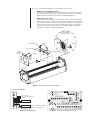
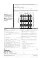
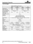
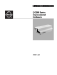
C2400M-A (8/99)
HD35/HD3515 Series
Heater and Defroster Kit
®
3500 Pelco Way
Clovis, CA 93612-5699
USA
IMPORTANT SAFEGUARDS AND WARNINGS
In North America & Canada:
Tel (800) 289-9100
FAX (800) 289-9150
1.
Installation and servicing should only be done by qualified service personnel and conform
to all local codes.
2.
Only use replacement parts recommended by Pelco.
International Customers:
Tel (1-559) 292-1981
FAX (1-559) 348-1120
Prior to installation and use of this product, the following WARNINGS should be observed.
The product and/or manual may bear the following marks:
This symbol indicates that dangerous voltage constituting a risk of
electric shock is present within
this unit.
www.pelco.com
This symbol indicates that there
are important operating and maintenance instructions in the literature accompanying this unit.
CAUTION:
RISK OF ELECTRIC SHOCK.
DO NOT OPEN.
Please thoroughly familiarize yourself with the information in this manual prior to installation
and operation.
DESCRIPTION
Heater and defroster kits in the HD35/HD3515 Series are designed for enclosures in the EH3500
Series and EH3515L Legacy® Series. The HD35 Heater and Defroster Kit is designed for enclosures
only in the EH3508 Series and EH3512 Series. The HD3515 Heater and Defroster Kit is designed
for enclosures only in the EH3515 Series and EH3515L Legacy® Series.
These kits contain a thermostatically controlled heater and a continuous-duty defroster. The heater
turns on when the temperature drops to 50°F (10°C) and turns off when the temperature reaches
80°F (27°C).
The heater and defroster are attached to a bracket that replaces the window brackets currently
used to hold the viewing window in place. Because of this bracket, the viewing window size is
reduced to a two-inch (5.08 cm) diameter circle.
The HD3515 Heater and Defroster Kit contains two heaters. You install one heater in the front of
the enclosure and the other heater in the rear of the enclosure. The rear heater is attached to a
rear heater bracket, and the rear heater bracket attaches to the rear of the enclosure. If you are
also installing a blower kit, you install the rear heater bracket between the blower and rear of the
enclosure.
Models
HD35-1
HD35-2
HD35-3
HD3515-1
HD3515-2
HD3515-3
Heater and defroster kit for EH3508 and EH3512 enclosures; 120 VAC; 13 watts
Heater and defroster kit for EH3508 and EH3512 enclosures; 24 VAC; 13 watts
Heater and defroster kit for EH3508 and EH3512 enclosures; 230 VAC; 13 watts
Heater and defroster kit for EH3515 and EH3515L enclosures; 120 VAC; 23 watts
Heater and defroster kit for EH3515 and EH3515L enclosures; 24 VAC; 23 watts
Heater and defroster kit for EH3515 and EH3515L enclosures; 230 VAC; 23 watts
INSTALLATION
The following items are supplied:
1
1
1
Heater and defroster attached to the front heater bracket
Heater attached to the rear heater bracket (HD3515 Series and HD3515L Series only)
PC board
Hardware to attach the heater bracket(s)
EH3508/EH3512 Series
EH3515/EH3515L Series
4
3/8-inch screws
4
3/8-inch screws
4
#6 nylon washers
4
#6 nylon washers
2
1/4-inch Phillips pan head screws
2
#6 lock washers
Hardware to attach the PC board (EH3508/EH3512/EH3515 only)
2
6-32 x 3/8-inch Phillips pan head screws
4
#6 nylon washers
1
#6 lock washer
1.
Disconnect all sources of power from the enclosure.
2.
Unlatch and open the lid.
3.
Remove the camera and camera sled.
a.
Disconnect the power and video from the camera.
b.
Loosen the screws that hold the camera sled in place.
c.
Slide the sled forward so it can be lifted out over the screws. Do not lift the sled
out yet.
d.
Retighten the screws so the sliding bar under the sled lip will not move. This will assure
that you reinstall the camera and sled in the same place.
e.
Remove the camera and sled.
4.
If there is a heater pad installed in the bottom of the enclosure or a defroster pad installed
around the viewing window, disconnect and remove these pads.
5.
Remove the bottom window bracket, and then remove the top window bracket. Important…
Do not try to reinstall the top and bottom window brackets.
6.
Attach the heater bracket (with heater and defroster attached) to the inside face of the window
using the screws provided (refer to Figure 1).
7.
If you are installing the HD3515 Heater and Defroster Kit, perform the following steps:
a.
If a blower was previously installed in the enclosure, remove the blower now.
b.
Place the rear heater bracket (with attached heater) at the rear of the enclosure (refer
to Figure 1). Be sure the heater is at the bottom of the enclosure and faces the rear of
the enclosure.
c.
Do one of the following:
If a blower was previously installed, place the blower against the rear heater bracket
and attach to the enclosure using the screws previously removed from the blower. Be
sure the arrow on the blower housing is pointing toward the viewing window.
Or…
Using the screws provided, attach the rear heater bracket to the rear of the enclosure.
8.
9.
Do the following only for enclosures in the EH3512 Series and EH3515 Series:
a.
Place the PC board at the rear of the enclosure in front of the blower (if installed) and
heater bracket. Lay the PC board across the bottom of the enclosure with the thermostat
and connectors facing up. Note…If a blower is not installed, place the PC board
approximately 1 1/2 inches in front of the rear heater bracket.
b.
Using the two 6-32 x 3/8-inch self tapping screws, two star washers, and four nylon
washers provided, attach the PC board to the slots running along the bottom of the
enclosure (refer to Figure 1).
Route the heater and defroster wires from the front of the enclosure so they will be underneath
the camera sled or between the track rail and body of the enclosure.
10. Do one of the following depending on the model number of the enclosure:
•
EH3512 Series and EH3515 Series
Connect the heater and defroster wires to the PC board (refer to Figure 2). Be sure the
wires are not obstructing other accessories within the enclosure. If you are installing
HD3515-2 Heater Kit (24 VAC), refer to Table A, 24 VAC Wiring Distances.
•
EH3515L Legacy® Series
Connect the front and rear heater wires to the HTRS connector (P5) on the circuit board
and the defroster wires to the FAN connector (P4) (refer to Figure 3). You are installing
a lower wattage defroster. You must connect the defroster to FAN (P4) on the PC board
to operate continuously. If you have a blower installed (which is also connected to P4),
splice the defroster wires to the fan wires. If you are installing HD3515-2 Heater Kit
(24 VAC), refer to Table A, 24 VAC Wiring Distances.
EH3515 SERIES
AND EH3515L SERIES
ENCLOSURES ONLY
REAR
HEATER
BRACKET
LOCK WASHER
SCREW
HEATER
NYLON WASHER
FRONT
HEATER
BRACKET
NYLON WASHER
HEATER
PC BOARD
DEFROSTER
Figure 1. Heater and Defroster Kit Installation
24/120/230 VAC MODELS
1
2
3
4
5
6
7
8
9
10
INPUT, AC HIGH
INPUT, AC LOW (NEUTRAL)
GROUND
DEFROSTER
FRONT HEATER
REAR HEATER
MODELS HD35 AND HD3515 SERIES
MODEL HD3515 SERIES ONLY
Figure 2. Wiring Diagram
Figure 3. PC Board Component Locations
11. Reinstall the camera and sled. Caution…If the wiring is routed underneath the camera sled,
be sure you do not bind the wiring when reinstalling the camera sled and camera.
12. Close the enclosure lid, and latch.
13. Reconnect power to the enclosure.
Table A. 24 VAC Wiring Distances
The following are the recommended maximum distances for 24 VAC applications and are calculated
with a 10-percent voltage drop. (Ten percent is generally the maximum allowable voltage drop
for AC-powered devices.)
20
10
20
Total vA consumed
30
NOTE: Distances are calculated
in feet; values in parentheses
are meters.
40
50
60
70
80
90
100
283
(86)
141
(42)
94
(28)
70
(21)
56
(17)
47
(14)
40
(12)
35
(10)
31
(9)
28
(8)
18
16
451
716
(137) (218)
225
358
(68) (109)
150
238
(45) (72)
112
179
(34) (54)
90
143
(27) (43)
75
119
(22) (36)
64
102
(19) (31)
56
89
(17) (27)
50
79
(15) (24)
45
71
(13) (21)
14
12
10
1142
(348)
571
(174)
380
(115)
285
(86)
228
(69)
190
(57)
163
(49)
142
(43)
126
(38)
114
(34)
1811
(551)
905
(275)
603
(183)
452
(137)
362
(110)
301
(91)
258
(78)
226
(68)
201
(61)
181
(55)
2880
(877)
1440
(438)
960
(292)
720
(219)
576
(175)
480
(146)
411
(125)
360
(109)
320
(97)
288
(87)
Maximum distance from transformer to load
Wire Gauge
EXAMPLE: An enclosure that
requires 80 vA and is installed
35 feet (10 m) from the transformer would require a minimum
wire gauge of 20 AWG.
PRODUCT WARRANTY AND RETURN INFORMATION
WARRANTY
Pelco will repair or replace, without charge, any merchandise proved defective in material or
workmanship for a period of one year after the date of shipment.
Exceptions to this warranty are as noted below:
• Five years on FT/FR8000 Series fiber optic products.
• Three years on Genex ® Series products (multiplexers, server, and keyboard).
• Three years on Camclosure ® and fixed camera models, except the CC3701H-2,
CC3701H-2X, CC3751H-2, CC3651H-2X, MC3651H-2, and MC3651H-2X camera models,
which have a five-year warranty.
• Two years on standard motorized or fixed focal length lenses.
• Two years on Legacy ®, CM6700/CM6800/CM9700 Series matrix, and DF5/DF8 Series
fixed dome products.
• Two years on Spectra ®, Esprit®, ExSite™, and PS20 scanners, including when used in
continuous motion applications.
• Two years on Esprit ® and WW5700 Series window wiper (excluding wiper blades).
• Eighteen months on DX Series digital video recorders, NVR300 Series network video
recorders, and Endura ™ Series distributed network-based video products.
• One year (except video heads) on video cassette recorders (VCRs). Video heads will be
covered for a period of six months.
• Six months on all pan and tilts, scanners or preset lenses used in continuous motion
applications (that is, preset scan, tour and auto scan modes).
Pelco will warrant all replacement parts and repairs for 90 days from the date of Pelco
shipment. All goods requiring warranty repair shall be sent freight prepaid to Pelco, Clovis,
California. Repairs made necessary by reason of misuse, alteration, normal wear, or accident
are not covered under this warranty.
Pelco assumes no risk and shall be subject to no liability for damages or loss resulting from
the specific use or application made of the Products. Pelco’s liability for any claim, whether
based on breach of contract, negligence, infringement of any rights of any party or product
liability, relating to the Products shall not exceed the price paid by the Dealer to Pelco for
such Products. In no event will Pelco be liable for any special, incidental or consequential
damages (including loss of use, loss of profit and claims of third parties) however caused,
whether by the negligence of Pelco or otherwise.
The above warranty provides the Dealer with specific legal rights. The Dealer may also have
additional rights, which are subject to variation from state to state.
If a warranty repair is required, the Dealer must contact Pelco at (800) 289-9100 or
(559) 292-1981 to obtain a Repair Authorization number (RA), and provide the following
information:
1. Model and serial number
2. Date of shipment, P.O. number, Sales Order number, or Pelco invoice number
3. Details of the defect or problem
If there is a dispute regarding the warranty of a product which does not fall under the
warranty conditions stated above, please include a written explanation with the product
when returned.
Method of return shipment shall be the same or equal to the method by which the item was
received by Pelco.
RETURNS
In order to expedite parts returned to the factory for repair or credit, please call the factory at
(800) 289-9100 or (559) 292-1981 to obtain an authorization number (CA number if returned
for credit, and RA number if returned for repair).
All merchandise returned for credit may be subject to a 20% restocking and refurbishing
charge.
Goods returned for repair or credit should be clearly identified with the assigned CA or RA
number and freight should be prepaid. Ship to the appropriate address below.
If you are located within the continental U.S., Alaska, Hawaii or Puerto Rico, send goods to:
Service Department
Pelco
3500 Pelco Way
Clovis, CA 93612-5699
If you are located outside the continental U.S., Alaska, Hawaii or Puerto Rico and are
instructed to return goods to the USA, you may do one of the following:
If the goods are to be sent by a COURIER SERVICE, send the goods to:
Pelco
3500 Pelco Way
Clovis, CA 93612-5699 USA
If the goods are to be sent by a FREIGHT FORWARDER, send the goods to:
Pelco c/o Expeditors
473 Eccles Avenue
South San Francisco, CA 94080 USA
Phone: 650-737-1700
Fax: 650-737-0933
REVISION HISTORY
Manual #
C2400M
C2400M-A
C2400M-A
Date
6/99
7/99
8/99
Comments
Original version.
Revised HD3515 series wattage. Revised Legacy® wiring instructions.
Revised parts lists. Revised Figure 1.
Pelco, the Pelco logo, Camclosure, Esprit, Genex, Legacy, and Spectra are registered trademarks of Pelco.
Endura and ExSite are trademarks of Pelco.
© Copyright 1999, Pelco.
All rights reserved.