1
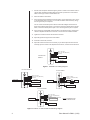
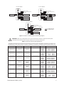
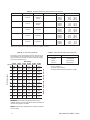
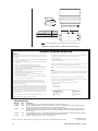
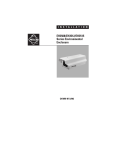
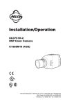
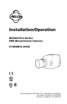
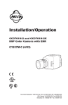
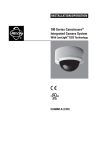
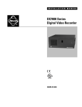
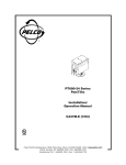
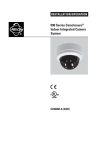
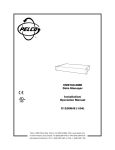
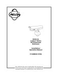
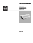
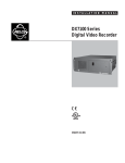
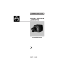
®
EH3508/EH3512/
EH3515 Series
Environmental
Enclosure
Installation/
Operation Manual
C478M-L (11/03)
Pelco • 3500 Pelco Way, Clovis • CA 93612-5699 USA • Pelco Online @ http://www.pelco.com
In North America and Canada: Tel (800) 289-9100 or FAX (800) 289-9150 • DataFAX (800) 289-9108
International Customers: Tel (1-559) 292-1981 or FAX (1-559) 348-1120 • DataFAX (1-559) 292-0435
IMPORTANT SAFEGUARDS AND WARNINGS
Prior to installation and use of this product, the following WARNINGS should be observed.
1.
Installation and servicing should only be done by qualified service personnel and conform to all local codes.
2.
Unless the unit is specifically marked as a NEMA Type 3, 3R, 3S, 4, 4X ,6 or 6P enclosure, it is designed for indoor use only and it must not be installed where exposed to
rain and moisture.
3.
Only use replacement parts recommended by Pelco.
4.
After replacement/repair of this unit’s electrical components, conduct a resistance
measurement between line and exposed parts to verify the exposed parts have not
been connected to line circuitry.
5.
The installation method and materials should be capable to supporting four times the
weight of the enclosure, pan/tilt, camera and lens combination.
The product and/or manual may bear the following marks:
This symbol indicates that dangerous voltage
constituting a risk of electric shock is present
within this unit.
This symbol indicates that there are important operating and maintenance instructions
in the literature accompanying this unit.
CAUTION:
RISK OF ELECTRIC SHOCK.
DO NOT OPEN.
Please thoroughly familiarize yourself with the information in this manual prior to installation
and operation.
DESCRIPTION
The EH3508/EH3512/EH3515 Series are indoor/outdoor light-duty camera enclosures designed for use with various cameras on the market and accommodate fixed focal length or
motorized zoom lenses, with or without auto-iris operation.
The lid of the enclosure is hinged in the front providing easy access during installation and
when camera and lens adjustments are necessary. The camera sled also serves as an elevation block. You can remove, flip, and then reinstall the sled to elevate the camera. All wiring and cabling is brought into the enclosure through adjustable glands at the bottom rear
of the enclosure.
The rear link-lock latch can be used with a padlock of suitable size for applications requiring
additional security.
MODELS
EH3508
EH3508-1
Enclosure, indoor/outdoor, 8.75-inch (22.23 cm) lower body length. (CE)
Same as EH3508 except unit is supplied with 120 VAC heater and defroster,
13 watts.
EH3508-2
Same as EH3508 except unit is supplied with 24 VAC heater and defroster,
13 watts. (CE)
EH3508-3
Same as EH3508 except unit is supplied with 230 VAC heater and defroster,
13 watts.
EH3512
Enclosure, indoor/outdoor, 12.75-inch (32.38 cm) lower body length. (CE)
EH3512-1
Same as EH3512 except unit is supplied with 120 VAC heater, defroster,
and blower, 17 watts.
EH3512-1HD Same as EH3512 except unit is supplied with 120 VAC heater and defroster,
13 watts.
EH3512-2
Same as EH3512 except unit is supplied with 24 VAC heater, defroster, and
blower, 15 watts. (CE)
EH3512-2HD Same as EH3512 except unit is supplied with 24 VAC heater and defroster,
13 watts. (CE)
2
Pelco Manual C478M-L (11/03)
EH3512-3
EH3512-3HD
EH3515
EH3515-1
EH3515-1HD
EH3515-2
EH3515-2HD
EH3515-3
EH3515-3HD
Same as EH3512 except unit is supplied with 230 VAC heater, defroster,
and blower, 22 watts.
Same as EH3512 except unit is supplied with 230VAC heater and defroster,
13 watts.
Enclosure, indoor/outdoor, 15.75-inch (40.00 cm) lower body length. (CE)
Same as EH3515 except unit is supplied with 120 VAC heater, defroster,
and blower, 27 watts.
Same as EH3515 except unit is supplied with 120 VAC heater and defroster,
23 watts.
Same as EH3515 except unit is supplied with 24 VAC heater, defroster, and
blower, 25 watts. (CE)
Same as EH3515 except unit is supplied with 24 VAC heater and defroster,
23 watts. (CE)
Same as EH3515 except unit is supplied with 230 VAC heater, defroster,
and blower, 32 watts.
Same as EH3515 except unit is supplied with 230 VAC heater and defroster,
23 watts.
INSTALLATION
The following items are supplied to mount the enclosure:
2
2
2
1/4-20 x .500-inch hex head screws
Flat washers
Split washers
The following items are supplied to mount the camera:
2
1/4-20 x .375-inch Phillips-head screws
Perform the following steps to install the enclosure, camera, and lens:
1.
Unlatch and open the lid.
2.
Remove the camera sled from the rail.
a. Loosen the screws that hold the camera sled in place.
b. Slide the sled forward so it can be lifted out over the screws.
c. Remove the sled.
d. Remove the parts tied to the sled.
3.
If you are wiring the enclosure with cable, remove the glands and nuts from the parts
bag and install them in the bottom of the enclosure. If you are wiring the enclosure
with conduit, do not install the glands.
4.
Attach the enclosure body to the appropriate mount using the instructions provided
with the mount.
Attach the enclosure through the threaded mounting holes in the bottom of the enclosure. Use the 1/4-20 x .500 screws and washers provided (in the parts bag). Completely tighten the screws to attach the enclosure body to the mounting surface.
5.
Attach the camera to the sled with the 1/4-20 x .375-inch Phillips-head screws provided (in the parts bag). You can attach the camera to either side of the sled. The side
of the sled to which you mount the camera depends on the type of camera and lens
you are attaching.
The edges of the sled are bent–one side up and the other side down. On one side of
the sled, the lip is wide; on the other side of the sled, the lip is narrow. In a typical installation, you mount the camera so that the holes in the wide lip of the sled fit over the
sled mounting screws.
However, you can elevate the sled if you are installing a camera with a low optical center line or a camera with a large diameter lens. To elevate the sled (and therefore elevate the camera), flip the sled over so that the holes in the narrow lip of the sled fit
over the sled mounting screws.
6.
Pelco Manual C478M-L (11/03)
Move the sled so that the sled mounting screws extend through the narrow part of sled
mounting holes, and partially tighten the sled mounting screws.
3
7.
Pull the video and power cables through the glands or conduit on the bottom of the enclosure. Refer to Tables A and B to determine the size of power wire to use. Refer to
Table C for the type of video coaxial cable to use.
8.
Attach the cables to the camera.
9.
If the enclosure has accessories that require power, connect the power to pins 1 and 2
on the PC Board (refer to Figures 1, 2, and 3 for information about accessory wiring).
Connect ground to pin 3 if required.
You can connect the camera power to the PC board if the voltages are the same between the accessories and camera. If you want to connect the camera power to the PC
board, connect the camera power to pins 1 and 2. Connect ground to pin 3 if required.
10. If the camera lens is adjustable, extend the lens to its maximum length; verify that the
camera is adjusted with the lens a minimum of 1/2 inch from the enclosure window.
11. Tighten the screws that secure the sled to the enclosure.
12. Adjust the glands for a tight fit around the cables.
13. Close the enclosure lid, and latch.
14. Adjust the camera focus and iris if necessary. If you need to adjust the focus and iris
manually, open the enclosure lid, adjust the focus and iris, and close the enclosure lid.
24/120/230 VAC
MODELS
INPUT, AC HIGH
INPUT, AC LOW (NEUTRAL)
GROUND
1
2
3
4
5
6
7
8
9
10
DEFROSTER
HEATER
Figure 1. EH3508-1/-2/-3 Wiring Diagram
120 VAC MODELS
DEFROSTER
1
2
3
4
5
6
7
8
9
10
24 VAC MODEL
INPUT, AC HIGH
INPUT, AC LOW (NEUTRAL)
GROUND
BLOWER
DEFROSTER
HEATER
INPUT, AC HIGH
INPUT, AC LOW (NEUTRAL)
GROUND
1
2
3
4
5
6
7
8
9
10
RED DIODE
BLK BRIDGE
RED
BLK
BLOWER
CAP
HEATER
230 VAC MODEL
DEFROSTER
1
2
3
4
5
6
7
8
9
10
INPUT, AC HIGH
INPUT, AC LOW (NEUTRAL)
GROUND
RESISTOR
NOTE: BLOWER APPLIES
TO -1/-2/-3 MODELS ONLY.
120 VAC BLOWER
HEATER
Figure 2. EH3512-1/-1HD/-2/-2HD/-3/-3HD Wiring Diagram
4
Pelco Manual C478M-L (11/03)
120 VAC MODEL
DEFROSTER
24 VAC MODEL
INPUT, AC HIGH
INPUT, AC LOW (NEUTRAL)
GROUND
1
2
3
4
5
6
7
8
9
10
DEFROSTER
BLOWER
FRONT HEATER
INPUT, AC HIGH
INPUT, AC LOW (NEUTRAL)
GROUND
1
2
3
4
5
6
7
8
9
10
RED DIODE
BLK BRIDGE
RED
BLK
BLOWER
CAP
FRONT HEATER
REAR HEATER
REAR HEATER
230 VAC MODEL
DEFROSTER
1
2
3
4
5
6
7
8
9
10
INPUT, AC HIGH
INPUT, AC LOW (NEUTRAL)
GROUND
RESISTOR
NOTE: BLOWER APPLIES
TO -1/-2/-3 MODELS ONLY.
120 VAC BLOWER
FRONT HEATER
REAR HEATER
Figure 3. EH3515-1/-1HD/-2/-2HD/-3/-3HD Wiring Diagram
CAUTION: When using a single power source for both camera and accessories, consider the camera power
consumption when determining the wire gauge. Table A does not include camera power.
Table A. Enclosure Accessory Wiring Distances
The following cable sizes are the minimum recommended for use with the heater and defroster combination in enclosures in the
EH3508 Series, and the heater, defroster, and blower combination in enclosures in the EH3512 Series and EH3515 Series only.
Model Number
Input Voltage
Accessories
Power Consumption
Cable Size
Cable Distance
EH3508-1
EH3512-1HD
120 VAC
at 60 Hz
Heater
Defroster
13 watts
EH3508-2
EH3512-2HD
24 VAC
at 60 Hz
Heater
Defroster
13 watts
EH3508-3
EH3512-3HD
230 VAC
at 50 Hz
Heater
Defroster
13 watts
EH3512-1
120 VAC
at 60 Hz
Heater
Defroster
Blower
17 watts
EH3512-2
24 VAC
at 60 Hz
Heater
Defroster
Blower
15 watts
EH3512-3
230 VAC
at 50 Hz
Heater
Defroster
Blower*
22 watts
EH3515-1
120 VAC
at 60 Hz
Heater
Defroster
Blower
27 watts
20 AWG
18 AWG
16 AWG
14 AWG
20 AWG
18 AWG
16 AWG
14 AWG
20 AWG
18 AWG
16 AWG
14 AWG
20 AWG
18 AWG
16 AWG
14 AWG
20 AWG
18 AWG
16 AWG
14 AWG
20 AWG
18 AWG
16 AWG
14 AWG
20 AWG
18 AWG
16 AWG
14 AWG
5,456 ft (1,662 m)
8,680 ft (2,645 m)
13,777 ft (4,199 m)
21,978 ft (6,698 m)
218 ft
(66 m)
347 ft
(105 m)
551 ft
(167 m)
879 ft
(267 m)
20,045 ft (6,109 m)
31,890 ft (9,720 m)
50,612 ft (15,426 m)
80,738 ft (24,608 m)
4,172 ft (1,271 m)
6,658 ft (2,023 m)
10,535 ft (3,211 m)
16,806 ft (5,122 m)
189 ft
(57 m)
300 ft
(91 m)
477 ft
(145 m)
761 ft
(231 m)
11,845 ft (3,610 m)
18,844 ft (5,743 m)
29,907 ft (9,115 m)
47,709 ft (14,541 m)
29 ft
(8 m)
47 ft
(14 m)
75 ft
(22 m)
120 ft
(36 m)
*Blower and resistor are 4.5 watts each for a total circuit power of 9 watts.
Pelco Manual C478M-L (11/03)
(Continued on next page)
5
Table A. Enclosure Accessory Wiring Distances (Continued)
Model Number
Input Voltage
Accessories
Power Consumption
Cable Size
EH3515-2
24 VAC
at 60 Hz
Heater
Defroster
Blower
25 watts
EH3515-3
230 VAC
at 50 Hz
Heater
Defroster
Blower*
32 watts
EH3515-1HD
120 VAC
at 60 Hz
Heater
Defroster
23 watts
EH3515-2HD
24 VAC
at 60 Hz
Heater
Defroster
23 watts
EH3515-3HD
230 VAC
at 50 Hz
Heater
Defroster
23 watts
20 AWG
18 AWG
16 AWG
14 AWG
20 AWG
18 AWG
16 AWG
14 AWG
20 AWG
18 AWG
16 AWG
14 AWG
20 AWG
18 AWG
16 AWG
14 AWG
20 AWG
18 AWG
16 AWG
14 AWG
Cable Distance
128 ft
204 ft
323 ft
516 ft
21 ft
34 ft
55 ft
88 ft
21 ft
66 ft
54 ft
87 ft
108 ft
172 ft
274 ft
437 ft
11 ft
18 ft
28 ft
45 ft
(39 m)
(62 m)
(98 m)
(157 m)
(6 m)
(10 m)
(16 m)
(26 m)
(6 m)
(20 m)
(16 m)
(26 m)
(32 m)
(52 m)
(83 m)
(133 m)
(3 m)
(5 m)
(8 m)
(13 m)
*Blower and resistor are 4.5 watts each for a total circuit power of 9 watts.
Table C. Video Coaxial Cable Wiring Distances
Table B. 24 VAC Wiring Distances
The following are the recommended maximum distances for 24
VAC applications and are calculated with a 10-percent voltage
drop. (Ten percent is generally the maximum allowable voltage
drop for AC-powered devices.)
Wire Gauge
10
283
(86)
451
(137)
716
(218)
1142
(348)
1811
(551)
2880
(877)
20
141
(42)
225
(68)
358
(109)
571
(174)
905
(275)
1440
(438)
30
94
(28)
150
(45)
238
(72)
380
(115)
603
(183)
960
(292)
40
70
(21)
112
(34)
179
(54)
285
(86)
452
(137)
720
(219)
50
56
(17)
90
(27)
143
(43)
228
(69)
362
(110)
576
(175)
60
47
(14)
75
(22)
119
(36)
190
(57)
301
(91)
480
(146)
70
40
(12)
64
(19)
102
(31)
163
(49)
258
(78)
411
(125)
80
35
(10)
56
(17)
89
(27)
142
(43)
226
(68)
360
(109)
90
31
(9)
50
(15)
79
(24)
126
(38)
201
(61)
320
(97)
100
28
(8)
45
(13)
71
(21)
114
(34)
181
(55)
288
(87)
Maximum distance from transformer to load
Total VA consumed
20 AWG 18 AWG 16 AWG 14 AWG 12 AWG 10 AWG
Total VA (0.5mm2) (1.0mm2) (1.5mm2) (2.5mm2) (4.0mm2) (6.0mm2)
Cable Type*
Maximum Distance
RG59/U
RG6/U
RG11/U
750 ft (229 m)
1,000 ft (305 m)
1,500 ft (457 m)
* Minimum cable requirements:
75 ohms impedance
All-copper center conductor
All-copper braided shield with 95% braid coverage
EXAMPLE: An enclosure that requires 80 vA and is
installed 35 feet (10 m) from the transformer would require a
minimum wire gauge of 20 AWG.
NOTE: Distances are calculated in feet; values in parentheses are meters.
6
Pelco Manual C478M-L (11/03)
OPERATION
If your enclosure has a thermostatically controlled heater, the thermostat is set to turn on at
50°F (10°C) and to turn off at 80°F (27°C).
If your enclosure has a blower and/or defroster, they operate continuously.
MAINTENANCE
Regularly scheduled maintenance prolongs the operational life and appearance of the
equipment. Clean the window regularly with a soft cloth using a mild, nonabrasive detergent
and water to maintain picture clarity.
SERVICE MANUAL
If you need to repair the camera enclosure, obtain a service manual in one of the following
ways:
•
Go to Pelco’s web site at ftp://www.pelco.com and find service manual C478SM.
•
Call Pelco’s DataFax service at 1-800-289-9108 or 1-559-292-0435 and request document number 24788.
•
Contact Pelco’s Literature Department and request service manual C478SM.
SPECIFICATIONS
Camera Mounting:
Camera and
Lens Size
Viewing Window:
Viewing Area
EH3508/EH3512/
EH3515:
All other models:
Cable Entry:
Cable Entry Holes:
Latch:
GENERAL
Construction:
Dimensions:
Environment:
Weight
Multiple holes on adjustable camera sled; camera sled mounts in
threaded strip for easier removal and can be inverted for additional
camera elevation.
Accommodates camera and lens combinations (including BNC connector) up to 2.87 in. W x 3.00 in. H (7.28 x 7.62 cm) and the following lengths:
EH3508:
6.80 in. (17.27 cm)
EH3508-1/-2/-3:
5.00 in. (12.70 cm)
EH3512:
10.25 in. (26.03 cm)
EH3512-1/-2/-3:
9.00 in. (22.86 cm)
EH3512-1HD/-2HD/-3HD:
10.00 in. (25.40 cm)
EH3515:
13.25 in. (33.66 cm)
EH3515-1/-2/-3:
12.00 in. (30.48 cm)
EH3515-1HD/-2HD/-3HD:
13.00 in. (33.02 cm)
Lexan®, .187-inch (4.75 mm) thick, optically clear, impact-resistant,
MR5 coated (U.L. 94HB rated).
2.25 in. H x 2.63 in. W (5.71 x 6.68 cm)
2.00-inch (5.08 cm) diameter circle
Two PG13.5 compression glands on bottom at rear of enclosure;
maximum cable diameter 0.47-inch (1.19 cm).
0.875-inch diameter; will accept 0.50-inch (1.27 cm) conduit fitting
when compression gland is removed.
Link-lock No. 3, stainless steel, can be secured with padlock (not
supplied).
Extruded and die-cast aluminum body
Refer to Figure 4
-10° to 120°F (-23° to 49°C)
EH3508:
2.67 lb (1.21 kg)
EH3508-1/-2/-3:
2.76 lb (1.25 kg)
EH3512:
3.40 lb (1.58 kg)
EH3512-1/-2/-3/-1HD/-2HD/-3HD: 3.85 lb (1.75 kg)
EH3515:
4.10 lb (1.86 kg)
EH3515-1/-2/-3/-1HD/-2HD/-3HD: 4.47 lb (2.03 kg)
(Design and product specifications subject to change without notice.)
Pelco Manual C478M-L (11/03)
7
5.14
(13.05)
A
3.88
(9.86)
B
C
EH3508
EH3512
EH3515
A
10.75 (27.30)
14.75 (37.47)
17.75 (45.09)
B
8.75 (22.22)
12.75 (32.38)
15.75 (40.00)
C
7.32 (18.59)
11.25 (28.57)
14.25 (36.20)
2.00
(5.08)
NOTE: VALUES IN PARENTHESES ARE CENTIMETERS; ALL OTHERS ARE INCHES
Figure 4. EH3508, EH3512, EH3515 Dimension Drawing
WARRANTY AND RETURN INFORMATION
WARRANTY
Pelco will repair or replace, without charge, any merchandise proved defective in material or
workmanship for a period of one year after the date of shipment. Exceptions to this warranty are
as noted below:
• Five years on Pelco manufactured cameras (CC3500/CC3600/CC3700 and MC3500/MC3600
Series); two years on all other cameras.
• Three years on Genex® Series (multiplexers, server, and keyboard) and 090 Series Camclosure®
Camera System.
• Two years on 100/150, 200 and 300 Series Camclosure® Camera Systems.
• Two years on cameras and all standard motorized or fixed focal length lenses.
• Two years on Legacy®, CM6700/CM6800/CM6800E/CM8500/CM9500/CM9740/CM9760
Matrix, DF5 and DF8 Series Fixed Dome products.
• Two years on Spectra®, Esprit®, and PS20 Scanners, including when used in continuous
motion applications.
• Two years on Esprit and WW5700 series window wiper (excluding wiper blades).
• Eighteen months on DX Series digital video recorders.
• One year (except video heads) on video cassette recorders (VCRs). Video heads will be
covered for a period of six months.
• Six months on all pan and tilts, scanners or preset lenses used in continuous motion applications (that is, preset scan, tour and auto scan modes).
Pelco will warrant all replacement parts and repairs for 90 days from the date of Pelco
shipment. All goods requiring warranty repair shall be sent freight prepaid to Pelco, Clovis,
California. Repairs made necessary by reason of misuse, alteration, normal wear, or accident
are not covered under this warranty.
Pelco assumes no risk and shall be subject to no liability for damages or loss resulting from the
specific use or application made of the Products. Pelco’s liability for any claim, whether based on
breach of contract, negligence, infringement of any rights of any party or product liability, relating
to the Products shall not exceed the price paid by the Dealer to Pelco for such Products. In no
event will Pelco be liable for any special, incidental or consequential damages (including loss of
use, loss of profit and claims of third parties) however caused, whether by the negligence of
Pelco or otherwise.
The above warranty provides the Dealer with specific legal rights. The Dealer may also have
additional rights, which are subject to variation from state to state.
If a warranty repair is required, the Dealer must contact Pelco at (800) 289-9100 or (559) 292-1981 to
obtain a Repair Authorization number (RA), and provide the following information:
1. Model and serial number
2. Date of shipment, P.O. number, Sales Order number, or Pelco invoice number
3. Details of the defect or problem
If there is a dispute regarding the warranty of a product which does not fall under the warranty conditions
stated above, please include a written explanation with the product when returned.
Method of return shipment shall be the same or equal to the method by which the item was received by
Pelco.
RETURNS
In order to expedite parts returned to the factory for repair or credit, please call the factory at (800) 289-9100
or (559) 292-1981 to obtain an authorization number (CA number if returned for credit, and RA number if
returned for repair).
All merchandise returned for credit may be subject to a 20% restocking and refurbishing charge.
Goods returned for repair or credit should be clearly identified with the assigned CA or RA number and
freight should be prepaid. Ship to the appropriate address below.
If you are located within the continental U.S., Alaska, Hawaii or Puerto Rico:
Service Department
Pelco
3500 Pelco Way
Clovis, CA 93612-5699
If you are located outside the continental U.S., Alaska, Hawaii or Puerto Rico:
Intermediate Consignee
Ultimate Consignee
American Overseas Air Freight
Pelco
320 Beach Road
3500 Pelco Way
Burlingame, CA 94010
Clovis, CA 93612-5699
USA
USA
REVISION HISTORY
Manual #
C478M-H
C478M-I
Date
6/97
8/98
C478M-J
6/99
C478M-K
7/99
C478M-L
11/03
Comments
Rev H. Revised to include new models (EH3515, EH3515-1, EH3515-2, EH3515-3).
Removed installation instructions for heater and blower kits, which have a separate manual. Moved exploded assembly
diagram and parts list to new service/maintenance manual. Added certifications.
Moved the EH3508 Series enclosures from manual C1435M-A. Updated the description, installation instructions, and
specifications. Updated wiring diagrams and dimension drawing. Modified per ECO 99-4749, which changed heater and
defroster design.
Incorporated addendum of July 1, 1999. Added watts to model numbers. Added footnote to explain discrepancy of 230 VAC
blower wattage. Revised camera and lens dimensions for heater/defroster models.
Updated certifications and corrected lens size specification.
® Pelco, the Pelco logo, Spectra, Genex, Legacy, Esprit, and Camclosure are registered trademarks of Pelco.
8
© Copyright 2003, Pelco.
All rights reserved.
Pelco Manual C478M-L (11/03)