1
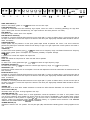
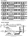
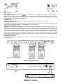
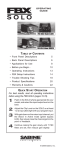
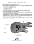
12
3
4
5
6
7
8
910
II
12
13
14
HIGH GAIN INPUT (1)
I
Used for most electric guitars. It is 6 dB louder than the Low Gain input.
LOW GAIN INPUT (2)
Provided for instruments that have extremely high outputs, which can result in overdriving (distorting) the High Gain
input. If both inputs are used simultaneously, the output levels are the same (both are Low Gain).
PRE GAIN (3)
Controls the input volume level of the amplifier.
PRE-EQ PATCH JACKS (4)
Provided for connecting external effects devices into the signal path. To patch an effects device, connect the send jack to
the input of the device. Connect the output of the device to the return jack. High-quality shielded cables should be used for
these connections.
OPERATION NOTE:
Volume pedals may be patched in at this point; pedal output should be patched into “return”, and “send” should be
patched into pedal input. Instrument should connect directly to high or low gain inputs when volume pedal is connected in
this configuration
LOW EQ (5)
An active tone control (shelving type, +/- 15 dB) that varies the low frequency range. CAUTION: Excessive low frequency
boost causes greater power consumption and increases possibility of speaker damage.
MID EQ (6)
A passive tone control that adjusts mid frequencies.
SHIFT (7)
Shifts and selects the frequencies at which the Mid control operates.
HIGH EQ (8)
An active tone control (peak/notch type, +/- 15 dB) that varies the high frequency range.
PRESENCE (ACTIVE) (9)
An active tone control (+I5 dB) that varies the extreme high frequency range. 0 to +15 boost (increase).
SENSITIVITY (10)
Controls the overall volume level of the amplifier. The final level adjustment should be made after the desired sound has
been achieved.
EFFECTS PATCH 1 (11)
Provided for connecting external effects devices into the signal path. To patch an effects device, connect the send jack to
the input of the device. Connect the output of the device to the return jack. High-quality shielded cables should be used for
these connections.
EFFECTS PATCH 2 (12)
Provided for connecting external effects devices into the signal path. To patch an effects device, connect the send jack to
the input of the device. Connect the output of the device to the return jack. High-quality shielded cables should be used for
these connections.
REVERB (13)
Reverberation is an echo effect. Rotate clockwise to increase the effect. Remote footswitch can control On/Off.
PILOT LIGHT LED (14)
Illuminates when AC power is being supplied to the amp.
GROUND SWITCH (15)
Three position rocker-type switch which, in most applications, should be operated in its center or zero position. There
may be some situations when audible hum and/or noise will come from the loudspeaker. If this situation arises, position
the ground switch to either positive or negative (+ or -) or until the noise is minimized. NOTE: Should the noise problem
continue, consult your Authorized Peavey Dealer, the Peavey Factory, or a qualified service technician. THE GROUND
SWITCH IS NOT FUNCTIONAL ON 220/240 VOLT MODELS.
POWER SWITCH (16)
Depress the switch to the “On” position. The red pilot light (LED) will illuminate indicating power is being supplied to the
unit.
15 16
Tone Settings
Adjust to Taste
Steel Guitar E9th Neck
Adjust to Taste
Steel Guitar C6th Neck
Adjust to Taste
Adjust to Taste
Violin
Adjust to ‘Taste
Adjust to Taste
Lead Guitar - Country
Adjust to Taste
Adjust to Taste
Lead Guitar - Jazz
Adjust to Taste
Adjust to Taste
Tone settings given are general and will vary according to type of guitar, type and gauges of strings, type of pickup
and even type of pick. Personal taste, playing style, and type of music greatly contribute to desired tonality.
BLOCK DIAGRAM
PRE-EQ
PRE AMP
TONE
SWITCH
LOGIC
SEND
EFFECTS 1
RETURN
SWITCH
LOGIC
I
PWR AMP PREAMP
IN
OUT
4 OHM
SPEAKER
+-Y
T
4 FT. SW.
PWR. AMP
AvYv
R. SW.
JY
RETURN
r 7
:y
1
REVERB
SESSION” 400 LTD
SEND
EFFECTS 2
LE?EL
THIS BLOCK DIAGRAM SHOWS THE SIGNAL PATH WITHIN THE AMPLIFIER. IN ORDER TO
THOROUGHLY UNDERSTAND THE FUNCTIONS OF THE AMPLIFIER, PLEASE STUDY THE
BLOCK DIAGRAM CAREFULLY.
SESSION@ 400 LIMITED ENGINEERING
SPECIFICATIONS
Preamp Low Gain Input: (6 dB pad)
Impedance: High Z, 44 K ohms
Nominal Input Level: -16 dBv,
160 mV RMS
Minimum Input Level: -30 dBv,
30 mV RMS
Maximum Input Level: +16 dBv, 6.0 V RMS
POWER AMPLIFIER SECTION
Rated Power & Load
210 Watts into 4 ohms with DDT’”
compression
Power @ Clipping: (typical)
(5% THD, 1 kHz, 120 VAC line)
240 Watts RMS into 4 ohms
Pre EQ Patch Send: (pedal send)
Load impedance: 10 K ohms or greater
Nominal output: -12 dBv, 0.25 V RMS
Maximum output: +8 dBv, 2.5 V RMS
Frequency Response:
+O, -2 dB, 80 Hz to 10 kHz, @
200 Watts RMS into 4 ohms
Total Harmonic Distortion:
Less than 0.2%, 100 mW to 200 Watts
RMS, 60 Hz to 10 kHz, 4 ohms (typically
below O.i%)
Hum & Noise:
Greater than 100 dB below rated power
Power Consumption: (domestic)
600 Watts @ 120 VAC 60 Hz
PREAMP SECTION
The following specs are measured @ 1 kHz
with the controls preset as follows:
Low & High EQ @ 0 dB
Mid & Shift EQ @ 10
Presence EQ @ 0
Sensitivity @ 5
High dynamics reverb @ 0
Nominal levels are with pre gain @ 5
Minimum levels are with pre gain @ 10
Preamp High Gain Input:
Impedance: High Z, 220 K ohms
Nominal Input Level: -22 dBv, 80 mV RMS
Minimum Input Level: -36 dBv,
15mVRMS
Maximum Input Level: +lO dBv, 3.0 V RMS
Pre EQ Patch Return: (pedal return)
Impedance: High Z, 220 K ohms
Designed input level: -12 dBv, 0.25 V RMS
(Switching jack providing pre EQ patch
send to pre EQ patch return connection
when not used)
Effects 1 & 2 Patch Sends:
Load impedance: 1 K ohms or greater
Nominal output: -10 dBv, 0.3 V RMS
Maximum output: +lO dBv, 3 V RMS
Effects 1 & 2 Patch Returns:
Impedance: High Z, 100 K ohms
Designed Input Level: -10 dBv, 0.3 V RMS
(Switching jacks providing effects patch
send to effects patch return connections
when not used)
Balanced Line Out:
Load Impedance: 600 ohms or greater
Nominal Output: -10 dBv, 0.3 V RMS
Maximum Output: +lO dBv, 3 V RMS
(XLR male connector, transformer driven;
special equalization circuitry employed)
System Hum 81 Noise @ Nominal Input
Levels:
(20 Hz to 20 kHz unweighted)
84 dB below rated power
Equalization:
Low: +/-15 dB @ 80 Hz, active shelving
Mid: +O, -12 dB, passive notch
Shift: 300 Hz to 1 kHz range of mid notch
High: +/-15 dB @ 2 kHz, active
peak/notch
Pres: -0, +15 dB @ 8 kHz, active shelving
External Footswitch Function:
Reverb defeat (when reverb control
raised)
Effects 1 patch return defeat
Effects 2 patch return defeat
Preamp Out:
Load impedance: 1 K ohms or greater
Nominal Output: 0 dBv; 1 V RMS
Maximum Output: +18 dBv, 8 V RMS
Power Amp In:
Impedance: High Z, 10 K ohms
Designed Input Level: 0 dBv, 1 V RMS
(Switching jack providing preamp out to
power amp in connection when not used)
AN OPTIONAL COVER IS AVAILABLE FOR
THE SESSION@ 400 LIMITED DIRECTLY
FROM THE FACTORY. THE PART NUMBER
IS #6890065 AND THE COST IS $21 .OO.
Prices, features and specifications are subject to change without notice.
LINE CORD (17)
(120V products only)
For your safety, we have incorporated a 3-wire line (mains) cable with proper grounding facilities. It is not advisable to
remove the ground pin under any circumstances. If it is necessary to use the equipment without proper grounding
facilities, suitable grounding adaptors should be used. Less noise and greatly reduced shock hazard exists when the unit
is operated with the proper grounded receptacles.
SPEAKER JACK (18)
Provided for connection of internal and/or external speakers. Minimum total impedance is 4 ohms.
BALANCED LINE OUT (19)
Provides 600 ohm, transformer balanced signal to be used as “direct” patch into mixing consoles, tape recorders, etc. The
signal at this point has been frequency compensated for low noise operation.
PREAMP OUT/POWER AMP IN (20)
These jacks are provided for in-line patching of effects devices. To patch an effects unit, connect the Preamp Output to the
Input of the device. Next, connect the output of the device to the Power Amp Input (high-quality shielded cables must be
used for these connections). The Preamp Output can also be used to route the amplified signal to a mixing console, tape
recorder, etc. Connect the Preamp Output, using a shielded cable, to an input of the tape recorder, mixer, etc. This patch
does not affect the operation of the amplifier. NOTE: The preamp output level is approximately 1 volt RMS and is of
relatively low impedance (600 ohms). Any effects device used in this effects loop must be capable of receiving 1 volt input
and providing 1 volt output in order to properly drive the power amp. The Power Amp Input has an internal switch which
disconnects the internal preamp.
FOOTSWITCH JACK (21)
Provided for connection of the supplied remote footswitch. Footswitch is used to defeat reverb, post effects loop 1, and
post effects loop 2.
Effects Device or Volume Pedal
Effects Device
Effects Device
Shielded Cables Must Be Used
Session 400
600 ohm balanced out to mixer,
tape deck, etc. (frequency compensated)
0
LINE LEVEL EFFECTS DEVICE
0
Shielded Cables Must Be Used
EFFECTS PATCH
THIS LIMITED WARRANTY VALID ONLY WHEN PURCHASED AND REGISTERED IN THE UNITED STATES OR CANADA. ALL EXPORTED PRODUCTS ARE SUBJECT TO
WARRANTY AND SERVICES TO BE SPECIFIED AND PROVIDED BY THE AUTHORIZED DISTRIBUTOR FOR EACH COUNTRY.
Ces clauses de garanlie ne sent vaiables qu’aux Eta&-Unis et au Canada. Dans tous les autres pays, les clauses de garantie et de maintenance sent llxees parle distributeur national et
assuree par lul seion la legislation en vigueur.
Diese Garantie 1st nur In den USA and Kanada gultig. Alle Export-Produkte sind der Garantie und dem Service des lmporleurs des jewelligen Landes unterworfen.
Esta garantia es vallda solamente cuando el product0 es comprado en E.U. continentales o en Canada. Todos 10s productos que Sean comprados en el extranjero, estan sujetos a las
garantias y servicio que cada distribuidor autorizado determine y ofrezca en 10s diferentes paises.
ONE-YEAR LIMITED WARRANTY/REMEDY
PEAVEY ELECTRONICS CORPORATION (“PEAVEY”) warrants this product, EXCEPT for covers, footswitches, patchcords, tubes and meters, to be free from defects In material
and workmanship for a period of one (1) year from date of purchase, PROVIDED, however that this limIted warranty is extended only to the original retail purchaser and is subject to the
conditions, exclusions and limitations hereinafter set forth:
PEAVEY OO-DAY LIMITED WARRANTY ON TUBES AND METERS
If this product contains tubesor meters, Peavey warrants thefubes or meters contained in the product to be free from defects in material and workmanship for a period of ninety (90)
days from date of purchase, PROVIDED, however, that this limited warranty IS extended only to the original retall purchaser and is also subject to the conditions, exclusions and
limitations hereinafter set forth.
CONDITIONS, EXCLUSIONS AND LIMITATIONS OF LIMITED WARRANTIES
These limited warranties shall be void and of no effect if:
a. The first purchase of the product is for the purpose of resale; or
b. The oriqinal retail purchase is not made from an AUTHORIZED PEAVEY DEALER: or
c. The product has been damaged by accident or unreasonable use, neglect, Improper service or maintenance, or other causes not arising out of defects in material or
workmanship; or
d. The serial number affixed to the product is altered, defaced or removed.
In the event of a defect in material and/or workmanship covered by this limited warranty, Peavey will:
a. In the case of tubes or meters, replace the defective component without charge;
b. In other covered cases (i.e., cases involving anythlng other than covers, footswitches, patchcords, tubes or meters), repair the defect in matenal or workmanship or replace
the product, at Peavey’s option;
and provided, however, that, in any case, all costs of shipping, if necessary, are paid by you, the purchaser.
THE WARRANTY REGISTRATION CARD SHOULD BE ACCURATELY COMPLETED AND MAILED TO AND RECEIVED BY PEAVEY WITHIN FOURTEEN (14) DAYS FROM THE
DATE OF YOUR PURCHASE.
In order to obtain service under these warranties, you must:
a. Bring the defective item to any AUTHORIZED PEAVEY DEALER or AUTHORIZED PEAVEY SERVICE CENTER and present therewith the ORIGINAL PROOF OF
PURCHASE supplied to you by the AUTHORIZED PEAVEY DEALER tn connection with your purchase from him of this product.
If the DEALER or SERVICE CENTER is unable to provide the necessary warranty service you WIII be directed to the nearest other PEAVEY AUTHORIZED DEALER or
AUTHORIZED PEAVEY SERVICE CENTER which can provide such service.
OR
b. Ship the defective item, prepaid, to:
PEAVEY ELECTRONICS CORPORATION
International Service Center
Highway 80 East
MERIDIAN, MS 39301
including therewith a complete, detailed descnptlon of the problem, together with a legible copy of the original PROOF OF PURCHASE and a complete return address. Upon
Peavey’s receiot of these Items:
If the befect IS remedial under these limited warranties and the other terms and conditions expressed herein have been complied with, Peavey will provide the necessary
warranty service to repair or replace the product and will return it, FREIGHT COLLECT, to you, the purchaser.
Peavey’s liability to the purchaser for damages from any cause whatsoever and regardless of the form of action, including negligence, IS limited to the actual damages up to the
greater of $500.00 or an amount equal to the purchase price of the product that caused the damage or that is the subject of or is directly related to the cause of action. Such purchase
price
be that in effect for the specific product when the cause of action arose. This limitation of liability will not apply to claims for personal injury or damage to real property or
tangible personal property allegedly caused by Peavey’s negligence. Peavey does not assume liability for personal injury or property damage arising out of or caused by a non-Peavey
alteration or attachment, nor does Peavey assume any responsibility for damage to Interconnected non-Peavey equipment that may result from the normal functioning and
maintenance of the Peavey equipment.
UNDER NO CIRCUMSTANCES WILL PEAVEY BE LIABLE FOR ANY LOST PROFITS, LOST SAVINGS, ANY INCIDENTAL DAMAGES OR ANY CONSEQUENTIAL DAMAGES
ARISING OUT OF THE USE OR INABILITY TO USE THE PRODUCT, EVEN IF PEAVEY HAS BEEN ADVISED OF THE POSSIBILITY OF SUCH DAMAGES.
THESE LIMITED WARRANTIES ARE IN LIEU OF ANY AND ALL WARRANTIES, EXPRESS OR IMPLIED, INCLUDING, BUT NOT LIMITED TO, THE IMPLIED WARRANTIES OF
MERCHANTABILITY AND FITNESS FOR A PARTICULAR USE; PROVIDED, HOWEVER, THAT IF THE OTHER TERMS AND CONDITIONS NECESSARY TO THE EXISTENCE OF
THE EXPRESS, LIMITED WARRANTIES, AS HEREINABOVE STATED, HAVE BEEN COMPLIED WITH, IMPLIED WARRANTIES ARE NOT DISCLAIMED DURING THE
APPLICABLE ONE-YEAR OR NINETY-DAY PERIOD FROM DATE OF PURCHASE OF THIS PRODUCT.
SOME STATES DO NOTALLOW LIMITATION ON HOW LONG AN IMPLIED WARRANTY LASTS, ORTHE EXCLUSION OR LIMITATION OF INCIDENTALOR CONSEQUENTIAL
DAMAGES, SO THE ABOVE LIMITATIONS OR EXCLUSIONS MAY NOT APPLY TO YOU. THESE LIMITED WARRANTIES GIVE YOU SPECIFIC LEGAL RIGHTS, AND YOU MAY
ALSO HAVE OTHER RIGHTS WHICH MAY VARY FROM STATE TO STATE.
THESE LIMITED WARRANTIES ARE THE ONLY EXPRESS WARRANTIES ON THIS PRODUCT, AND NO OTHER STATEMENT, REPRESENTATION, WARRANTY OR
AGREEMENT BY ANY PERSON SHALL BE VALID OR BINDING UPON PEAVEY.
In the event of any modification or disclaimer of express or implied warranties, or any limitation of remedies, contained herein conflicts with applicable law, then such modification,
disclaimer or limitation, as the case may be, shall be deemed to be modified to the extent necessary to comply with such law.
Your remedies for breach of these warranties are limited to those remedies provided herein ‘1 id Peavey Electronics Corporation gives this limited warranty only with respect to
equipment purchased in the United States of America.
INSTRUCTIONS -WARRANTY REGISTRATION CARD
1. Mail the completed WARRANTY REGISTRATION CARD to:
PEAVEY ELECTRONICS CORPORATION
POST OFFICE BOX 2898
MERIDIAN, MISSISSIPPI 39302-2898
a. Keep the PROOF OF PURCHASE. In the event warranty service is required during the warranty period. you will need this document. There will be no identification card
issued by Peavey Electronics Corporation.
2. IMPORTANCE OF WARRANTY REGISTRATION CARDS AND NOTIFICATION OF CHANGES OF ADDRESS:
a. Completion and mailing of WARRANTY REGISTRATION CARDS-Should notification become necessaryforanycondition that may requirecorrection, the REGISTRATION
CARD will help ensure that you are contacted and properly notified.
b. Notice of address changes - If you move from the address shown on the WARRANTY REGISTRATION CARD, you should notify Peavey of the change of address so as to
facilitate your receipt of any bulletins or other forms of notification which may become necessary in connection with any condition that may require dissemination of
information or correction.
3. You may contact Peavey directly by telephoning (601) 483-5365.
will
4. Please have the Peavey product name and serial number available when communicating with Peavey Customer Service.
Features and specifications subject to change without notice.
Peavey Electronics Corporation 711 A Street / Meridian, MS 39301 / U.S.A. / (601) 483-5365 / Telex 504115 / Fax 486-1278
01994
#80300811
Printed in U.S.A. 2/94